
SoftwareUserManual
Firmware v2.0.0 for all Ouster sensors
Ouster
Jan15,2021

Contents
1 SafetyandSafeUse 5
1.1 Safety & Legal Notices . . . . . . . . . . . . . . . . . . . . . . . . . . . . . . . . . . . . . . . . 5
1.2 Proper Assembly, Maintenance and Safe Use . . . . . . . . . . . . . . . . . . . . . . . . . . 7
1.2.1 Assemblage correct et utilisation sûre . . . . . . . . . . . . . . . . . . . . . . . . . . 8
2 ConnectingtoSensor 9
2.1 Network Configuration . . . . . . . . . . . . . . . . . . . . . . . . . . . . . . . . . . . . . . . . 9
2.2 Sensor Output Visualization . . . . . . . . . . . . . . . . . . . . . . . . . . . . . . . . . . . . . 10
3 SensorData 11
3.1 Coordinate Frames and XYZ Calculation . . . . . . . . . . . . . . . . . . . . . . . . . . . . . 11
3.1.1 Lidar Coordinate Frame . . . . . . . . . . . . . . . . . . . . . . . . . . . . . . . . . . . 11
3.1.2 Lidar Range to XYZ . . . . . . . . . . . . . . . . . . . . . . . . . . . . . . . . . . . . . . 12
3.1.3 Sensor Coordinate Frame . . . . . . . . . . . . . . . . . . . . . . . . . . . . . . . . . . 13
3.1.4 Combining Lidar and Sensor Coordinate Frame . . . . . . . . . . . . . . . . . . . . . 14
3.1.5 Lidar Intrinsic Beam Angles . . . . . . . . . . . . . . . . . . . . . . . . . . . . . . . . . 14
3.1.6 Lidar Range Data To Sensor XYZ Coordinate Frame . . . . . . . . . . . . . . . . . . 14
3.1.7 IMU Data To Sensor XYZ Coordinate Frame . . . . . . . . . . . . . . . . . . . . . . . 15
3.2 Lidar Data . . . . . . . . . . . . . . . . . . . . . . . . . . . . . . . . . . . . . . . . . . . . . . . 16
3.2.1 Lidar Data Format . . . . . . . . . . . . . . . . . . . . . . . . . . . . . . . . . . . . . . 16
3.2.2 Lidar Data Packet Size Calculation . . . . . . . . . . . . . . . . . . . . . . . . . . . . . 18
3.3 IMU Data . . . . . . . . . . . . . . . . . . . . . . . . . . . . . . . . . . . . . . . . . . . . . . . . 18
3.3.1 IMU Data Format . . . . . . . . . . . . . . . . . . . . . . . . . . . . . . . . . . . . . . . 18
3.4 Data Rates . . . . . . . . . . . . . . . . . . . . . . . . . . . . . . . . . . . . . . . . . . . . . . . 19
3.5 Range Performance by Lidar Mode . . . . . . . . . . . . . . . . . . . . . . . . . . . . . . . . 20
4 KeyFeatures 21
4.1 Azimuth Window . . . . . . . . . . . . . . . . . . . . . . . . . . . . . . . . . . . . . . . . . . . 21
4.1.1 Expected Sensor Behavior . . . . . . . . . . . . . . . . . . . . . . . . . . . . . . . . . . 22
4.1.2 Azimuth Window Examples . . . . . . . . . . . . . . . . . . . . . . . . . . . . . . . . . 22
4.2 Phase Lock . . . . . . . . . . . . . . . . . . . . . . . . . . . . . . . . . . . . . . . . . . . . . . . 22
4.2.1 Phase Locking Reference Frame . . . . . . . . . . . . . . . . . . . . . . . . . . . . . . 23
4.2.2 Phase Locking Commands . . . . . . . . . . . . . . . . . . . . . . . . . . . . . . . . . 23
4.2.3 Multi-sensor Example . . . . . . . . . . . . . . . . . . . . . . . . . . . . . . . . . . . . 24
4.2.4 Accuracy . . . . . . . . . . . . . . . . . . . . . . . . . . . . . . . . . . . . . . . . . . . . 25
4.2.5 Phase Locking Alerts . . . . . . . . . . . . . . . . . . . . . . . . . . . . . . . . . . . . . 25
4.3 Standby Operating Mode . . . . . . . . . . . . . . . . . . . . . . . . . . . . . . . . . . . . . . 26
4.3.1 Expected Sensor Behavior . . . . . . . . . . . . . . . . . . . . . . . . . . . . . . . . . . 26
4.3.2 Standby Operating Mode Examples . . . . . . . . . . . . . . . . . . . . . . . . . . . . 26
4.4 Cold Start . . . . . . . . . . . . . . . . . . . . . . . . . . . . . . . . . . . . . . . . . . . . . . . 27
4.4.1 Hardware Requirements . . . . . . . . . . . . . . . . . . . . . . . . . . . . . . . . . . . 27
4.4.2 Cold Start Operation . . . . . . . . . . . . . . . . . . . . . . . . . . . . . . . . . . . . . 27
4.4.3 Indications and Alerts . . . . . . . . . . . . . . . . . . . . . . . . . . . . . . . . . . . . 28
5 Time Synchronization 29
5.1 Timing Overview Diagram . . . . . . . . . . . . . . . . . . . . . . . . . . . . . . . . . . . . . . 29
5.2 Sensor Time Source . . . . . . . . . . . . . . . . . . . . . . . . . . . . . . . . . . . . . . . . . 30
5.2.1 Setting Ouster Sensor Time Source . . . . . . . . . . . . . . . . . . . . . . . . . . . . 30
2
5.2.2 External Trigger Clock Source . . . . . . . . . . . . . . . . . . . . . . . . . . . . . . . 32
5.3 NMEA Message Format . . . . . . . . . . . . . . . . . . . . . . . . . . . . . . . . . . . . . . . 33
6 Inputsand Interfaces 35
6.1 Web Interface . . . . . . . . . . . . . . . . . . . . . . . . . . . . . . . . . . . . . . . . . . . . . 36
6.2 Electrical and Mechanical Interface . . . . . . . . . . . . . . . . . . . . . . . . . . . . . . . . 37
7 Troubleshooting 38
7.1 Sensor Homepage and HTTP Server . . . . . . . . . . . . . . . . . . . . . . . . . . . . . . . . 38
7.2 Networking . . . . . . . . . . . . . . . . . . . . . . . . . . . . . . . . . . . . . . . . . . . . . . . 38
7.3 get_alerts . . . . . . . . . . . . . . . . . . . . . . . . . . . . . . . . . . . . . . . . . . . . . . . 38
7.4 Using Latest Firmware . . . . . . . . . . . . . . . . . . . . . . . . . . . . . . . . . . . . . . . . 40
8 HTTP API Reference 41
8.1 system/firmware . . . . . . . . . . . . . . . . . . . . . . . . . . . . . . . . . . . . . . . . . . . . 41
8.1.1 GET /api/v1/system/firmware . . . . . . . . . . . . . . . . . . . . . . . . . . . . . . . 41
8.2 diagnostics . . . . . . . . . . . . . . . . . . . . . . . . . . . . . . . . . . . . . . . . . . . . . . . 41
8.2.1 GET /api/v1/diagnostics/dump . . . . . . . . . . . . . . . . . . . . . . . . . . . . . . . 41
8.3 system/network . . . . . . . . . . . . . . . . . . . . . . . . . . . . . . . . . . . . . . . . . . . . . 42
8.3.1 GET /api/v1/system/network . . . . . . . . . . . . . . . . . . . . . . . . . . . . . . . . 42
8.3.2 GET /api/v1/system/network/ipv4 . . . . . . . . . . . . . . . . . . . . . . . . . . . . 43
8.3.3 GET /api/v1/system/network/ipv4/override . . . . . . . . . . . . . . . . . . . . . . . 43
8.3.4 PUT /api/v1/system/network/ipv4/override . . . . . . . . . . . . . . . . . . . . . . . 44
8.3.5 DELETE /api/v1/system/network/ipv4/override . . . . . . . . . . . . . . . . . . . . . 44
8.4 time . . . . . . . . . . . . . . . . . . . . . . . . . . . . . . . . . . . . . . . . . . . . . . . . . . . 45
8.4.1 GET /api/v1/time . . . . . . . . . . . . . . . . . . . . . . . . . . . . . . . . . . . . . . . 45
8.4.2 GET /api/v1/time/system . . . . . . . . . . . . . . . . . . . . . . . . . . . . . . . . . . 47
8.4.3 GET /api/v1/time/ptp . . . . . . . . . . . . . . . . . . . . . . . . . . . . . . . . . . . . 49
8.4.4 GET /api/v1/time/sensor . . . . . . . . . . . . . . . . . . . . . . . . . . . . . . . . . . 51
9 TCPAPI 53
9.1 Querying Sensor Info and Intrinsic Calibration . . . . . . . . . . . . . . . . . . . . . . . . . . 53
9.2 Querying Active or Staged Parameters . . . . . . . . . . . . . . . . . . . . . . . . . . . . . . 59
9.3 Setting Configuration Parameters . . . . . . . . . . . . . . . . . . . . . . . . . . . . . . . . . 63
10 APIChangelog 68
11 AlertsandErrors 72
11.1 Table of All Alerts and Errors . . . . . . . . . . . . . . . . . . . . . . . . . . . . . . . . . . . . 72
12 LidarPacket FormatUpdate 78
13 CrosstalkMitigationTutorial 80
13.1 Two Sensor Example . . . . . . . . . . . . . . . . . . . . . . . . . . . . . . . . . . . . . . . . . 80
14 Drivers 83
14.1 Open Source Drivers . . . . . . . . . . . . . . . . . . . . . . . . . . . . . . . . . . . . . . . . . 83
14.2 Ouster Studio . . . . . . . . . . . . . . . . . . . . . . . . . . . . . . . . . . . . . . . . . . . . . 83
15 PTPQuickstartGuide 84
15.1 Assumptions . . . . . . . . . . . . . . . . . . . . . . . . . . . . . . . . . . . . . . . . . . . . . . 84
15.2 Physical Network Setup . . . . . . . . . . . . . . . . . . . . . . . . . . . . . . . . . . . . . . . 84
15.2.1 Third Party Grandmaster Clock . . . . . . . . . . . . . . . . . . . . . . . . . . . . . . 84
3

15.2.2 Linux PTP Grandmaster Clock . . . . . . . . . . . . . . . . . . . . . . . . . . . . . . . 85
15.3 Example Network Setup . . . . . . . . . . . . . . . . . . . . . . . . . . . . . . . . . . . . . . . 86
15.4 Installing Necessary Packages . . . . . . . . . . . . . . . . . . . . . . . . . . . . . . . . . . . 86
15.5 Ethernet Hardware Timestamp Verification . . . . . . . . . . . . . . . . . . . . . . . . . . . 87
15.6 Configurations . . . . . . . . . . . . . . . . . . . . . . . . . . . . . . . . . . . . . . . . . . . . . 88
15.6.1 Configuring ptp4l for Multiple Ports . . . . . . . . . . . . . . . . . . . . . . . . . . . . 88
15.6.2 Configuring ptp4l as a Local Master Clock . . . . . . . . . . . . . . . . . . . . . . . . 90
15.6.3 Configuring phc2sys to Synchronize the System Time to the PTP Clock . . . . . . . 90
15.6.4 Configuring Chrony to Set System Clock Using PTP . . . . . . . . . . . . . . . . . . 91
15.7 Verifying Operation . . . . . . . . . . . . . . . . . . . . . . . . . . . . . . . . . . . . . . . . . . 93
15.7.1 HTTP API . . . . . . . . . . . . . . . . . . . . . . . . . . . . . . . . . . . . . . . . . . . . 93
15.7.2 LinuxPTP PMC Tool . . . . . . . . . . . . . . . . . . . . . . . . . . . . . . . . . . . . . . 93
15.7.3 Tested Grandmaster Clocks . . . . . . . . . . . . . . . . . . . . . . . . . . . . . . . . . 94
16 NetworkingGuide 95
16.1 Networking 101 . . . . . . . . . . . . . . . . . . . . . . . . . . . . . . . . . . . . . . . . . . . . 95
16.2 Windows . . . . . . . . . . . . . . . . . . . . . . . . . . . . . . . . . . . . . . . . . . . . . . . . 96
16.2.1 Connecting the Sensor . . . . . . . . . . . . . . . . . . . . . . . . . . . . . . . . . . . 96
16.2.2 The Sensor Homepage . . . . . . . . . . . . . . . . . . . . . . . . . . . . . . . . . . . . 96
16.2.3 Determining the IPv4 Address of the Sensor . . . . . . . . . . . . . . . . . . . . . . . 97
16.2.4 Determining the IPv4 Address of the Interface . . . . . . . . . . . . . . . . . . . . . 98
16.2.5 Setting the Host Interface to DHCP . . . . . . . . . . . . . . . . . . . . . . . . . . . . 98
16.2.6 Setting the Host Interface to Static IP . . . . . . . . . . . . . . . . . . . . . . . . . . . 99
16.2.7 Finding a Sensor with mDNS Service Discovery . . . . . . . . . . . . . . . . . . . . . 99
16.3 macOS . . . . . . . . . . . . . . . . . . . . . . . . . . . . . . . . . . . . . . . . . . . . . . . . . 101
16.3.1 Connecting the Sensor . . . . . . . . . . . . . . . . . . . . . . . . . . . . . . . . . . . 101
16.3.2 The Sensor Homepage . . . . . . . . . . . . . . . . . . . . . . . . . . . . . . . . . . . . 101
16.3.3 Determining the IPv4 Address of the Sensor . . . . . . . . . . . . . . . . . . . . . . . 101
16.3.4 Determining the IPv4 Address of the Interface . . . . . . . . . . . . . . . . . . . . . 102
16.3.5 Setting the Host Interface to DHCP . . . . . . . . . . . . . . . . . . . . . . . . . . . . 103
16.3.6 Setting the Host Interface to Static IP . . . . . . . . . . . . . . . . . . . . . . . . . . . 104
16.3.7 Finding a Sensor with mDNS Service Discovery . . . . . . . . . . . . . . . . . . . . . 104
16.4 Linux . . . . . . . . . . . . . . . . . . . . . . . . . . . . . . . . . . . . . . . . . . . . . . . . . . 106
16.4.1 Connecting the Sensor . . . . . . . . . . . . . . . . . . . . . . . . . . . . . . . . . . . 106
16.4.2 Setting the Interface to Link-Local Only . . . . . . . . . . . . . . . . . . . . . . . . . . 106
16.4.3 The Sensor Homepage . . . . . . . . . . . . . . . . . . . . . . . . . . . . . . . . . . . . 107
16.4.4 Determining the IPv4 Address of the Sensor . . . . . . . . . . . . . . . . . . . . . . . 108
16.4.5 Determining the IPv4 Address of the Interface . . . . . . . . . . . . . . . . . . . . . 109
16.4.6 Setting the Host Interface to DHCP . . . . . . . . . . . . . . . . . . . . . . . . . . . . 110
16.4.7 Setting the Host Interface to Static IP . . . . . . . . . . . . . . . . . . . . . . . . . . . 111
16.4.8 Finding a Sensor with mDNS Service Discovery . . . . . . . . . . . . . . . . . . . . . 113
17 Updating Firmware 114
17.1 Downgrading Firmware . . . . . . . . . . . . . . . . . . . . . . . . . . . . . . . . . . . . . . . 114
18 FirmwareChangelog 115
4

1 Safety and Safe Use
1.1 Safety & Legal Notices
All Ouster sensors have been evaluated to be Class1laserproductsper 60825-1: 2014(Ed. 3) and
operate in either the 850nm or 865nm band.
Tous les capteurs Ouster répondent aux critères des produitslaser de classe 1, selon la norme IEC
60825-1: 2014 (3ème édition) et émettent dans le domaine de l’infrarouge, à une longueur d’onde
de XXXXXXXXX environ.
FDA21CFR1040Notice: All Ouster sensors comply with FDA performance standards for laser prod-
ucts except for deviations pursuant to Laser Notice No. 56, dated January 19, 2018.
Notice FDA 21CFR1040: Tous les capteurs Ouster sont conformes aux exigences de performances
établies par la FDA pour les produits laser, à l’exception des écarts en application de l’avis nº56, daté
du 19 janvier 2018.
The following symbols appear on the product label and in the manual and have the following meaning.
This symbol indicates that the sensor emits laser radiation.
This symbol indicates the presence of a hot surface that may cause skin burn.
CAUTIONS:
All Ouster sensors are hermetically sealed units, and are not user-serviceable.
Use of controls, or adjustments, or performance of procedures other than those specified herein,
may result in hazardous radiation exposure.
5

Your use of any Ouster sensor is subject to the Terms of Sale that you signed with Ouster or your
distributor/integrator. Included in these terms is the prohibition on:
Removing or otherwise opening the sensor housing
Inspecting the internals of the sensor
Reverse-engineering any part of the sensor
Permitting any third party to do any of the foregoing
Operating the sensor without either the attached mount with which the sensor is shipped, or
attaching the sensor to a surface of appropriate thermal capacity runs the risk of having the
sensor overheat under certain circumstances.
This product emits Class 1 invisible laser radiation. The entire window is considered to be the
laser aperture. While Class 1 lasers are considered to be “eye safe”, avoid prolonged direct view-
ing of the laser and do not use optical instruments to view the laser.
When operated in an ambient temperature >40�°C, the metallic surfaces of the sensor may be
hot enough to potentially cause skin burn. Avoid skin contact with the sensor’s base, lid and
heatsink when the sensor is operated under these conditions.
PRECAUTIONS:
Tous les capteurs Ouster sont des unités hermétiquement scellées, qui ne peuvent être en-
tretenues ou modifiées par l’utilisateur.
L’utilisation de commandes, de réglages, ou l’exécution de procédures autres que celles spéci-
fiées dans le présent document peuvent entraîner des rayonnements laser dangereux.
L’utilisation d’un capteur Ouster est soumise aux conditions de vente signées avec Ouster ou le
distributeur/intégrateur, incluant l’interdiction de:
Retirer ou ouvrir de quelque façon le boîtier du capteur
Analyser les composants internes du capteur
Pratiquer la rétro-ingénierie de toute ou partie du capteur
Autoriser une tierce personne à mener les actions listées ci-dessus
L’utilisation du capteur sans son dissipateur thermique fourni lors de la livraison ou une utilisa-
tion qui ne maintiendrait pas un contact suffisant avec une surface aux propriétés thermiques
adéquates, présentent toutes deux un risque de surchauffe du capteur dans certaines circon-
stances.
Ce produit émet un rayonnement laser invisible de classe 1. L’ouverture de sortie du laser est
constituée par la fenêtre du capteur dans sa totalité. Même si les lasers de classe 1 ne sont pas
considérés comme dangereux pour les yeux, ne regardez pas directement le rayonnement laser
de façon prolongée et n’utilisez pas d’instruments optiques pour observer le rayonnement laser.
Lors d’une utilisation à température ambiante supérieure à 40°C, la surface métallique du cap-
teur peut présenter des risques de brûlures pour la peau. Dans ces conditions, il est important
6

d’éviter tout contact avec la partie superieure, la base ou le dissipateur thermique du capteur.
EquipmentLabel: Note that the equipment label, which includes model and serial number and notice
that the unit is a Class 1 Laser Product, is affixed to the underside of the Sensor Enclosure Base itself.
It is only visible after the attached mount with which the Sensor is shipped, is removed. Please refer
to location details in the Mounting section of the Hardware User Manual.
L’étiquettedel’équipement, comprenant le modèle, le numéro de série, et la classification du produit
laser (ici, classe 1), est apposée au dessous de la base du boîtier du capteur. Il n’est visible qu’après
avoir retiré le diffuseur de chaleur avec lequel le capteur est expédié. L’emplacement est décrit avec
précision dans le Manuel d’Utilisateur Hardware (Hardware User Manual), dans la section «Mounting»
Electromagnetic Compatibility: Your Ouster sensor is an FCC 47 CfR 15 Subpart B device. This device
complies with part 15 of the FCC Rules. Operation is subject to the following conditions: (1) This
device may not cause harmful interference, and (2) this device must accept any interference received,
including interference that may cause undesired operation.
“Ouster”, “OS0”, “OS1”, and “OS2” are all registered trademarks of Ouster, Inc. They may not be used
without express permission from Ouster, Inc.
If you have any questions about the above points, please contact legal@ouster.io.
1.2 Proper Assembly, Maintenance and Safe Use
All Ouster sensors may be easily setup by mounting to the base to a mounting with the correct mount-
ing hole pattern and following the interconnection instructions delineated in the Mounting section
of the Hardware User Manual. Any mounting orientation is acceptable. Each sensor is shipped at-
tached to a mount for test or normal use specified operating temperature range, but the sensor may
be mounted directly to any appropriate mount with Thermal Capacity appropriate for the application
of the user. Please contact Ouster for assistance with approving the use of user specific mounting
arrangements.
Any attempt to utilize the sensor outside the Environmental parameters delineated in the relevant
data sheet for your Ouster sensor may result in voiding of the warranty.
When power is applied, the sensor powers up and commences boot-up with the laser disabled. The
bootup sequence is approximately 60s in duration, after which the internal sensor optics subassembly
commences spinning, and the laser is activated, and the unit operates in the default 1024 x 10 Hz mode.
When the sensor is running, and the laser is operating, a faint red flickering light may be seen behind
the optical window. Note that the all Ouster sensors utilize either an 850nm or 865 nm infrared laser
that is only dimly discernable to the naked eye, while transmitting a laser eye-safe fundamental signal
in the respective IR band. Refer to the appropriate Hardware User Manual to determine the specific
wavelength of your sensor. While the sensor is fully Class 1 eye safe, Ouster strongly recommends
against peering into the optical window at close range while the sensor is operating. All Ouster sensors
are hermetically sealed units, and are not user-serviceable. Any attempt to unseal the enclosure has
the potential to expose the operator to hazardous laser radiation.
Ouster sensors are equipped with a multi-layer series of internal safety interlocks to ensure compli-
ance to Class 1 Laser Eye Safe limits.
The Sensor user interface may be used configure the sensor to a number of combinations of scan rates
7
and resolutions other than the default values of 1024 x 10 Hz resolution. In all available combinations,
the unit has been evaluated by an NRTL to remain within the classification of a Class 1 Laser Device
as per IEC 60825-1:2014 (Ed. 3).
1.2.1 Assemblagecorrectetutilisationsûre
Tous les capteurs Ouster s’installent facilement en fixant la base sur un support percé de trous concor-
dants et en suivant les instructions d’interconnexion décrites le Manuel d’Utilisateur Hardware (Hard-
ware User Manual). Toute orientation de montage est acceptable. Chaque capteur est expédié équipé
d’un dissipateur de chaleur, utilisable en phase de test et en conditions normales. Néanmoins tout
autre support présentant une capacité thermique appropriée pour l’application de l’utilisateur peut
être utilisé. Veuillez contacter Ouster dans le cas où un montage spécifique à votre application serait
nécessaire.
Toute tentative d’utilisation du capteur en dehors des paramètres environnementaux définis dans la
fiche technique de votre capteur Ouster peut entraîner l’annulation de la garantie.
Lorsque le capteur est sous tension, celui-ci démarre et commence son initialisation avec le laser dés-
activé. Le temps de démarrage est d’environ 60s, après quoi le sous-système optique entre en rotation
et le laser est activé, le capteur opère alors dans son mode par défaut de 1024 x 10 Hz. Lorsque le cap-
teur est en marche et que le laser est active, on peut apercevoir une faible lumière rouge vacillante
derrière la vitre teintée. Tous les capteurs Ouster utilisent des longueurs d’ondes infra-rouge de 850
ou 865 nm à peine perceptible pour l’œil humain, et le rayonnement laser IR émis est sans danger pour
les yeux. La longueur d’onde spécifique de votre capteur est disponible dans le Manuel d’Utilisateur
Hardware (Hardware User Manual). Cependant, bien que les rayonnements laser de classe 1 soient
sans danger dans des conditions raisonnablement prévisibles, Ouster recommande fortement de ne
pas regarder fixement la vitre teintée pendant que le capteur est en marche. Tous les capteurs Ouster
sont des unités hermétiquement scellées, qui ne peuvent pas être entretenues, modifiées ou réparées
par l’utilisateur. Toute tentative d’ouverture du boîtier a pour risque d’exposer l’opérateur à un rayon-
nement laser dangereux.
Les capteurs Ouster sont équipés d’une série de dispositifs de sécurité à plusieurs niveaux, de façon à
assurer en toutes circonstances le respect des limites d’irradiance correspondant aux rayonnements
lasers de classe 1, sans danger pour les yeux.
L’interface utilisateur du logiciel du capteur peut être utilisée pour configurer le capteur selon un cer-
tain nombre de combinaisons de vitesses de balayage et de résolutions autres que les valeurs utilisées
par défaut, respectivement de 1024 x 10 Hz.
8

2 Connecting to Sensor
Your Ouster sensor requires a computer with a gigabit Ethernet connection and a 24V supply. Option-
ally you may time synchronize the sensor through an external time source or through the computer
via PTP.
2.1 Network Configuration
The sensor is designed to communicate with a host machine through a variety of different methods
such a DHCP, IPv6/IPv4 link-local, and static IP.
On most systems you should be able to connect the sensor into your network or directly to a host
machine and simple use the senor hostname to communicate with it.
The sensor hostname is, os-991234567890.local, where 991234567890 is the sensor serial number.
For more detailed guidance on communicating with the sensor on various operating systems and net-
work settings please reference the Networking Guide in the Appendix.
Commands for setting and deleting a static IP address can be found in the HTTP API Reference section.
9

2.2 Sensor Output Visualization
After connecting to your sensor, you can quickly visualize the point cloud through either Ouster Studio
or with our sample drivers. Both Ouster Studio and our sample drivers are available for Linux, Mac, and
Windows. Please visit www.ouster.com/resources for the latest tools to visualize your sensor output.
10

3 Sensor Data
3.1 Coordinate Frames and XYZ Calculation
Ouster defines two coordinate frames:
The Lidar Coordinate Frame follows the Right Hand Rule convention and is a point cloud-centric
frame of reference that is the simplest frame in which to calculate and manipulate point clouds. The
X-axis points backwards towards the external connector, which is an unintuitive orientation that was
deliberately chosen to meet the following criteria:
data frames split at the back of the sensor i.e. the external connector
data frames start with the azimuth angle equal to 0°
All point cloud features including setting an azimuth window and phase locking are defined in the Lidar
Coordinate Frame.
The SensorCoordinateFrame follows the Right Hand Rule convention and is a mechanical housing-
centric frame of reference that follows robotics convention with X-axis pointing forward. Ouster-
provided drivers and visualizers represent data in the Sensor Coordinate Frame.
Note: All Ouster coordinate frames follow the Right Hand Rule, allowing for standard 3D transfor-
mation matrix math to convert between them. For multi-sensor systems that require calibration, this
Linear Algebra-based approach can be convenient. However, customers with single-sensor systems
may find it more intuitive to stay in the Lidar Coordinate Frame and take arithmetic shortcuts.
3.1.1 Lidar CoordinateFrame
The Lidar Coordinate Frame is defined at the intersection of the lidar axis of rotation and the lidar
optical midplane (a plane parallel to Sensor Coordinate Frame XY plane and coincident with the 0°
elevation beam angle of the sensor).
TheLidarCoordinateFrameaxes arearrangedwith:
positive X-axis pointed at encoder angle 0° and the external connector
positive Y-axis pointed towards encoder angle 90°
positive Z-axis pointed towards the top of the sensor
The Lidar Coordinate Frame is marked in both diagrams below with X
L
, Y
L
, and Z
L
.
11

3.1.2 Lidar Range toXYZ
Given the following information, range data may be transformed into 3D cartesian XYZ coordinates in
the Lidar Coordinate Frame:
Fromameasurementblockfromthe UDP packet:
encoder_count of the measurement block
range_mm value of the data block of the i-th channel
Fromtheget_beam_intrinsics TCPcommand:
lidar_origin_to_beam_origin_mm value
beam_altitude_angles array
beam_azimuth_angles array
The corresponding 3D point can be computed by
r = range_mm
n = lidar_origin_to_beam_origin_mm
θ
encoder
= 2π ·
(
1 −
encoder_count
90112
)
θ
azimuth
= −2π
beam_azimuth_angles[i]
360
ϕ = 2π
beam_altitude_angles[i]
360
x = (r − n) cos (θ
encoder
+ θ
azimuth
) cos(ϕ) + n cos (θ
encoder
)
y
= (
r
−
n
)
sin
(
θ
encoder
+
θ
azimuth
)
cos
(
ϕ
) +
n
sin
(
θ
encoder
)
z = (r − n) sin(ϕ)
Figures Fig. 3.1 and Fig. 3.2 show, respectively, a top-down and side view of the sensor.
Figure3.1: Top-down view of Lidar Coordinate Frame
12

Figure3.2: Side view of Lidar Coordinate Frame
3.1.3 SensorCoordinateFrame
The Sensor Coordinate Frame is defined at the center of the sensor housing on the bottom, with the
X-axis pointed forward, Y-axis pointed to the left and Z-axis pointed towards the top of the sensor. The
external connector is located in the negative x direction. The Sensor Coordinate Frame is marked in
the diagram below with X
S
, Y
S
, Z
S
.
Figure3.3: Top-down view of Sensor Coordinate Frame
13

Figure3.4: Side view of Sensor Coordinate Frame
3.1.4 Combining Lidar and Sensor CoordinateFrame
The Lidar Coordinate Frame’s positive X-axis (0 encoder value) is opposite the Sensor Coordinate
Frame’s positive X-axis to center lidar data about the Sensor Coordinate Frame’s positive X-axis. A
single measurement frame starts at the Lidar Coordinate Frame’s 0° position and ends at the 360°
position. This is convenient when viewing a “range image” of the Ouster Sensor measurements, al-
lowing the “range image” to be centered in the Sensor Coordinate Frame’s positive X-axis, which is
generally forward facing in most robotic systems.
The Ouster Sensor scans in the clockwise direction when viewed from the top, which is a negative
rotational velocity about the Z-axis. Thus, as encoder ticks increases from 0 to 90,111, the actual angle
about the Z-axis in the Lidar Coordinate Frame will decrease.
3.1.5 Lidar Intrinsic Beam Angles
The intrinsic beam angles for each beam may be queried with a TCP command get_beam_intrinsics
to provide an azimuth and elevation adjustmen offset to the each beam. The azimuth adjustment is
referenced off of the current encoder angle and the elevation adjustment is referenced from the XY
plane in the Sensor and Lidar Coordinate Frames.
3.1.6 LidarRangeDataToSensor XYZCoordinateFrame
For applications that require calibration against a precision mount or use the IMU data in combination
with the lidar data, the XYZ points should be adjusted to the Sensor Coordinate Frame. This requires
a Z translation and a rotation of the X,Y,Z points about the Z-axis. The z translation is the height of the
lidar aperture stop above the sensor origin, which is varies depending on the sensor you have, and the
data must be rotated 180° around the Z-axis. This information can be queried over TCP in the form of
a homogeneous transformation matrix in row-major ordering.
Example JSON formatted query using the TCP command get_lidar_intrinsics:
14

{
"lidar_to_sensor_transform": [-1, 0, 0, 0, 0, -1, 0, 0, 0, 0, 1, 36.180, 0, 0, 0, 1]
}
Which corresponds to the following matrix
M_lidar_to_sensor =
−1 0 0 0
0 −1 0 0
0 0 1 36.180
0 0 0 1
The table below lists all product lines’ distances of the aperture stop above the sensor origin for use
in the z translation.
ProductLine Lidaraperturestopabovesensororigin
OS0 36.180 mm
OS1 36.180 mm
OS2 74.296 mm
3.1.7 IMUDataToSensorXYZCoordinateFrame
The IMU is slightly offset in the Sensor Coordinate Frame for practical reasons. The IMU origin in the
Sensor Coordinate Frame can be queried over TCP in the form of an homogeneous transformation
matrix in row-major ordering.
Example JSON formatted query using the TCP command get_imu_intrinsics:
{
"imu_to_sensor_transform": [1, 0, 0, 6.253, 0, 1, 0, -11.775, 0, 0, 1, 7.645, 0, 0, 0, 1]
}
Which corresponds to the following matrix
M_imu_to_sensor =
1 0 0 6.253
0 1 0 −11.775
0 0 1 7.645
0 0 0 1
15

3.2 Lidar Data
3.2.1 Lidar Data Format
Note: Gen 1 OS1-16 and OS1-32 customers should note that upgrading to firmware v2.0.0 will change
their lidar packet format which reduces their data rates which is not backwards compatible with pre-
v2.0.0 clients. Please refer to the Lidar Packet Format Update section for more information on this
change.
Lidar data packets consist of 16 Measurement Blocks and vary in size relative to the number of chan-
nels in the sensor. The packet rate is dependent on the lidar mode. Words are 32 bits in length and
little endian. By default, lidar UDP data is forwarded to Port 7502.
Lidar frames are composed of 512, 1024, or 2048 measurement blocks, depending upon lidar mode
and are completely deterministic in number per frame and their monotonic order and position within
lidar data packets. This determinism allows for efficient lookup table-based decoding in clients.
Each Measurement Block contains:
HeaderBlock[128 bits]
Timestamp [64 bit unsigned int] - timestamp of the measurement in nanoseconds.
MeasurementID[16 bit unsigned int] - a sequentially incrementing measurement counting
up from 0 to 511, or 0 to 1023, or 0 to 2047 depending on lidar_mode.
Frame ID [16 bit unsigned int] - index of the lidar scan. Increments every time the sensor
completes a rotation, crossing the zero point of the encoder.
Encoder Count [32 bit unsigned int] - an azimuth angle as a raw encoder count, starting
from 0 with a max value of 90,111 - incrementing 44 ticks every azimuth angle in 2048 mode,
88 ticks in 1024 mode, and 176 ticks in 512 mode. Note: the encoder count is redundant with
the Measurement ID and will be deprecated in the future.
NChannelDataBlocks[96 bits each]
Range [32 bit unsigned int - only 20 bits used] - range in millimeters, discretized to the
nearest 3 millimeters.
SignalPhotons[16 bit unsigned int] - signal intensity photons in the signal return measure-
ment are reported.
Reflectivity [16 bit unsigned int] - sensor Signal Photons measurements are scaled based
on measured range and sensor sensitivity at that range, providing an indication of target
reflectivity. Calibration of this measurement has not currently been rigorously implemented,
but this will be updated in a future firmware release.
NearInfraredPhotons[16 bit unsigned int] - NIR photons related to natural environmental
illumination are reported.
MeasurementBlockStatus[32 bits]- indicates whether the measurement block contains valid
16

or zero-padded data in its channels’ Data Blocks. Valid = 0xFFFFFFFF, Padded = 0x0. If the
Measurement Block Status is Padded (e.g. in the case of channel data being dropped or if the
Measurement Block is outside of the azimuth window), values within the Channel Data Blocks
will be 0, but values within the Header Block remain valid.
17

3.2.2 Lidar Data PacketSizeCalculation
The table below shows the lidar data packet size breakdown for all products. Since the size of the
measurement block varies proportional the number of channels in a sensors, all sensors with the same
number of channels have the same lidar packet data structure and size.
Product Numberofwordsin Mea-
surementBlock
Size of single Measure-
mentBlock(Bytes)
Size of lidar
packet(Bytes)
OS1-16 53 212 3,392
OS0-32, OS1-32,
OS2-32
101 404 6,464
OS0-64, OS1-64,
OS2-64
197 788 12,608
OS0-128, OS1-
128, OS2-128
389 1,556 24,896
3.3 IMU Data
3.3.1 IMU Data Format
IMU UDP Packets are 48 Bytes long and by default are sent to Port 7503 at 100 Hz. Values are little
endian.
Each IMU data block contains:
IMUDiagnosticTime[64 bit unsigned int] - timestamp of monotonic system time since boot in
nanoseconds.
AccelerometerRead Time [64 bit unsigned int] - timestamp for accelerometer time relative to
timestamp_mode in nanoseconds.
Gyroscope Read Time [64 bit unsigned int] - timestamp for gyroscope time relative to times-
tamp_mode in nanoseconds.
AccelerationinX-axis[32 bit float] - acceleration in g.
AccelerationinY-axis [32 bit float] - acceleration in g.
AccelerationinZ-axis[32 bit float] - acceleration in g.
AngularVelocity about X-axis[32 bit float] - Angular velocity in deg per sec.
AngularVelocity about Y-axis[32 bit float] - Angular velocity in deg per sec.
AngularVelocity about Z-axis [32 bit float] - Angular velocity in deg per sec.
18

Note that the first timestamp (Words 0,1) is for diagnostics only and is rarely used under normal op-
eration.
The second two timestamps, (Words 2,3) and (Words 4,5), are sampled on the same clock as the lidar
data, so should be used for most applications.
Ouster provides timestamps for both the gyro and accelerometer in order to give access to the lowest
level information. In most applications it is acceptable to use the average of the two timestamps.
3.4 Data Rates
The table below calculates the data of all products operating at the highest lidar modes, 2048x10 or
1024x20 and assuming a default azimuth window of 360°. Providing a custom azimuth window can
further lower data rate. See the Azimuth Window section for details on setting a custom azimuth
window.
Product Lidar packet
size(Bytes)
Lidar packets
rate*(Hz)
IMU packet
size(Bytes)
IMU packets
persecond
Data rate
(Mbps)
OS1-16 3,392 1,280 48 100 34.77
OS0-32, OS1-
32, OS2-32
6,464 1,280 48 100 66.23
OS0-64, OS1-
64, OS2-64
12,608 1,280 48 100 129.14
OS0-128, OS1-
128, OS2-128
24,896 1,280 48 100 254.97
19

Lidar packets account for >99% of data coming from the sensor. For most applications, a gigabit
Ethernet network connection is required for reliable performance.
3.5 Range Performance by Lidar Mode
Depending upon the sensor’s lidar mode, the sensor can have an range boost multiplier from its base-
line range as listed on the datasheet. The baseline range is based off 1024x20 or 2048x10 lidar mode.
The table below shows the range boost multiplier for operating in other lidar modes.
Frame Rate / Horiz. Res 512 1024 2048
10 Hz 1.4x 1.2x 1x
20 Hz 1.2x 1x N/A
20

4 Key Features
4.1 Azimuth Window
Configuring the azimuth window is a feature to only turn on the UDP lidar data within a region of
interest. The region of interest is defined by a min bound and a max bound, both in millidegrees. As
a reminder, angles in this frame increment counter-clockwise when viewed from the top. Below is the
Lidar Coordinate Frame from a top-down perspective:
0° towards the external connector
90° a quarter turn counter-clockwise from the connector
180° opposite the connector
270° three quarter turns counter-clockwise from the connector
Configuring the azimuth window lowers the average output data rate of the sensor but does not affect
the peak output data rate of the sensor. It also does not stop the lasers from firing and thus does not
have an effect on power consumption or thermals.
21

4.1.1 ExpectedSensor Behavior
The sensor will round the input azimuth window bounds to the nearest Measurement Block IDs gen-
erating new ID-based bounds. The new bounds are used to mask Measurement Blocks in the lidar
data packets. Lidar packets containing only masked Measurement Blocks are not output, and there
may partially masked Measurement Blocks in the two bookended lidar packets in each frame. The
Measurement Block Status field will indicate the valid or masked/padded Measurement Blocks in any
partially masked lidar packets. (See the Lidar Data section for details on the lidar data format.)
The visualized output will contain jagged edges caused by the staggered, nonzero nature of the beam
azimuth angles. It is necessary to set more conservative (wider) bounds to push the jagged edges
beyond the desired window. This can be determined through trial and error or calculated determinis-
tically with knowledge of the queryable beam azimuth angles.
4.1.2 AzimuthWindowExamples
The TCP API Guide lists the command for setting an azimuth window. Below are example settings:
set_config_param azimuth_window [min_bound_millidegrees, max_bound_millidegrees]
// defaults setting of 360° window:
set_config_param azimuth_window [0, 360000]
// this will also default to a 360° window
set_config_param azimuth_window [0, 0]
// Set a region of interest between 0° to 180°.
set_config_param azimuth_window [0, 180000]
// Set a region of interest between 270° to 90° with 180° field of view
set_config_param azimuth_window [270000, 90000]
// Set a region of interest 90° to 270° with 180° field of view
set_config_param azimuth_window [90000, 270000]
// Set a region of interest between 0° to 90° with 90° field of view
set_config_param azimuth_window [0, 90000]
// Set a region of interest 90° to 360° with 270° field of view
set_config_param azimuth_window [90000, 0]
4.2 Phase Lock
Phase locking allows a sensor to consistently pass through a specific angle at a specific time on each
rotation. Phase locking is useful for synchronizing a sensor with other devices including camera, radar,
and other lidar.
A sensor must first be time-synchronized from an external source and must be in either the
TIME_FROM_PTP_1588 or TIME_FROM_SYNC_PULSE_IN timestamp_mode before entering phase lock.
22

4.2.1 PhaseLockingReferenceFrame
Phase locking commands use angles defined in the Lidar Coordinate Frame in millidegrees. As a re-
minder, angles in this frame increment counter-clockwise when viewed from the top. Below is the
Lidar Coordinate Frame from a top-down perspective:
0° towards the external connector
90° a quarter turn counter-clockwise from the connector
180° opposite the connector
270° three quarter turns counter-clockwise from the connector
4.2.2 PhaseLockingCommands
The TCP API Guide lists the two commands needed to acheive phase lock.
Command to enable or disable phase lock:
// by default, phase_lock_enable is false
set_config_param phase_lock_enable <true/false>
Command to set the phase lock offset angle in the Lidar Coordinate Frame:
23

// by default, phase_lock_offset value is 0
// <angle_in_millidegrees> is an int from [0, 360000]
set_config_param phase_lock_offset <angle_in_millidegrees>
4.2.3 Multi-sensorExample
In this example below, we are trying to phase lock all three sensors on the car so that they point towards
the front of the car at the same time. Note that their external connectors point in different directions.
Assuming the three sensors are properly time synchronized via an external source, the following shows
the netcat console input commands and responses from configuring the sensors so that they point
forward at the same time:
// set Sensor 1 to phase lock at 180°
$ nc sensor1_hostname 7501
set_config_param phase_lock_enable true
set_config_param
set_config_param phase_lock_offset 180000
set_config_param
reinitialize
reinitialize
save_config_params
save_config_params
// set Sensor 2 to phase lock at 90°
$ nc sensor2_hostname 7501
set_config_param phase_lock_enable true
set_config_param
set_config_param phase_lock_offset 90000
set_config_param
reinitialize
reinitialize
save_config_params
save_config_params
// set Sensor 2 to phase lock at 270°
$ nc sensor3_hostname 7501
(continues on next page)
24

(continued from previous page)
set_config_param phase_lock_enable true
set_config_param
set_config_param phase_lock_offset 270000
set_config_param
reinitialize
reinitialize
save_config_params
save_config_params
4.2.4 Accuracy
The following chart shows the expected angular position accuracy under normal operating conditions.
ProductLine Accuracy
10Hz 20Hz
OS0 and OS1 (Gen 1 and Gen 2) 0.5˚ 0.5˚
OS2 5˚ 10˚
4.2.5 PhaseLockingAlerts
The following alerts related to phase locking errors are listed below. For the full list of alerts and errors
see the Alerts and Errors section in the Appendix.
Table 4.1: Phase Lock Alerts
id category level description
0x01000050 MOTOR_CONTROL WARNING The phase lock offset error has exceeded the
threshold.
0x01000051 MOTOR_CONTROL ERROR The phase lock control failed to achieve a
lock multiple times; please contact Ouster at
https://ouster.com/tech-support.
0x01000024 STARTUP ERROR The phase lock control failed to achieve a lock
during startup.
25

4.3 Standby Operating Mode
Starting the firmware v2.0.0, the sensor can be commanded in and out of a low-power Standby Oper-
ating Mode that can be useful for power, battery, or thermal-conscious applications of the sensor.
The TCP config param operating_mode has a default value of "NORMAL". Setting it to "STANDBY" puts the
sensor into Standby Operating Mode upon reinitialization.
4.3.1 ExpectedSensor Behavior
Power draw in Standby mode 5W. The motor does not spin, and light is not visible from the window.
However, the sensor is on and listening to commands. The sensor status will be "STANDBY".
4.3.2 StandbyOperatingModeExamples
Below are example netcat console command input and responses for several use caes of the Standby
mode
// set sensor into Standby mode and keep sensor in Standby mode upon power-up at next use
set_config_param operating_mode "STANDBY"
set_config_param
reinitialize
reinitialize
save_config_params
save_config_params
// set sensor into Standby mode but have sensor start in the default Running mode upon power-up at next use:
set_config_param operating_mode "STANDBY"
set_config_param
reinitialize
reinitialize
// command sensor back into Running mode and save config
set_config_param operating_mode "NORMAL"
set_config_param
reinitialize
reinitialize
save_config_params
save_config_params
Note: auto_start_flag is the deprecated parameter name where auto_start_flag 0 is equivalent to
operating_mode "STANDBY" and auto_start_flag 1 is equivalent to operating_mode "NORMAL". Please use
operating_mode wherever possible in client code.
Warning: Use of auto_start_flag in firmware prior to v2.0.0 has unexpected behavior.
26

4.4 Cold Start
Starting in v2.0.0, there is software-enabled capability for power-up from lower temperatures for Gen
2 sensors. If the sensor detects that its environmental temperature is low, it will attempt to self-heat
in a warmup state before entering a normal operating state.
4.4.1 HardwareRequirements
Gen 1 sensors are not cold start-compatible on any firmware. While all sensors will attempt to start
at lower exhibit cold start behavior by going into the warmup state, only Gen 2 sensors are able to
successfully exit the warmup state into the normal operating state.
4.4.2 ColdStart Operation
There is nothing for the user to change about the sensor configuration to use this feature. The sensor
will automatically begin its warmup process in the coldest parts of its operating temperature range.
ProductLine Mintempspecs
OS0
-40°C min operating temp
8 mins to SENSOR_RUNNING
12 mins to lasers at temp (full range)
28W peak power
OS1
-40°C min operating temp
8 mins to SENSOR_RUNNING
12 mins to lasers at temp (full range)
28W peak power
OS2
-5°C min operating temp
22 mins to SENSOR_RUNNING
22 mins to lasers at temp (full range)
30W peak power
27

4.4.3 Indicationsand Alerts
In a cold start scenario, the sensor will have a short warmup phase; we’ve added in the additional
"WARMUP" status to indicate when the sensor is warming up.
$ nc os-992000123456 7501
get_sensor_info
{
"base_pn": "000-101323-03",
"base_sn": "101933001839",
"build_date": "2020-05-15T18:21:21Z",
"build_rev": "v2.0.0",
"image_rev": "ousteros-image-prod-aries-v2.0.0-20201120210617-staging",
"prod_line": "OS-1-128",
"prod_pn": "840-101855-02",
"prod_sn": "99200123456",
"proto_rev": "v1.1.1",
"status": "WARMUP"
}
The following alerts are related to cold start
Table 4.2: Cold Start Alerts
id category level description
0x01000053 WARMUP_ISSUE ERROR Sensor warmup process has failed.
0x0100004F WARMUP_ISSUE WARNING Sensor warmup process is taking longer
than expected; please ensure sensor is
thermally constrained per requirements.
28

5 Time Synchronization
5.1 Timing Overview Diagram
SignalpathwithMULTIPURPOSE_IOsetasinput
SignalpathwithMULTIPURPOSE_IOsetasoutput
29

5.2 Sensor Time Source
All lidar and IMU data are timestamped to a common timer with 10 nanosecond precision.
The common timer can be programmed to run off one of three clock sources:
An internal clock derived from a high accuracy, low drift oscillator.
An opto-isolated digital input from the external connector for timing off an external hard-
ware trigger such as a GPS. The polarity of this input signal is programmable. For instance,
both a GPS PPS pulse and a 30 Hz frame sync from an industrial camera can supply a timing
signal to the sensor.
Using the IEEE 1588 Precision Time Protocol. PTP provides the convenience of configuring
timing over a network that supports IEEE 1588 with no additional hardware signals.
5.2.1 SettingOusterSensor TimeSource
The source for measurement timestamps can be configured using the set_timestamp_mode TCP com-
mand. The available modes are described below:
30

Table5.1: Timestamp Modes
Command Response
TIME_FROM_INTERNAL_OSC Use the internal clock. Measurements are time stamped with ns
since power-on. Free running counter based on the sensor’s inter-
nal oscillator. Counts seconds and nanoseconds since sensor turn
on, reported at ns resolution (both a second and nanosecond reg-
ister in every UDP packet), but min increment is on the order of 10
ns.
TIME_FROM_SYNC_PULSE_IN A free running counter synced to the SYNC_PULSE_IN input
counts seconds (# of pulses) and nanoseconds since sensor turn
on. If multipurpose_io_mode is set to INPUT_NMEA_UART then the sec-
onds register jumps to time extracted from a NMEA $GPRMC mes-
sage read on the multipurpose_io port. Reported at ns resolution
(both a second and nanosecond register in every UDP packet), but
min increment is on the order of 10 ns.
TIME_FROM_PTP_1588 Synchronize with an external PTP master. A monotonically in-
creasing counter that will begin counting seconds and nanosec-
onds since startup. As soon as a 1588 sync event happens, the
time will be updated to seconds and nanoseconds since 1970. The
counter must always count forward in time. If another 1588 sync
event happens the counter will either jump forward to match the
new time, or slow itself down. It is reported at ns resolution (there
is both a second and nanosecond register in every UDP packet),
but the minimum increment varies.
If configuring the sensor to synchronize time from an external sync pulse, the pulse polarity can be
specified as described in the TCP API Guide. Pulse-in frequency is assumed to be 1 Hz. For example,
the below commands will set the sensor to expect an active low pulse and configure the seconds
timetamp to be pulse count since sensor startup:
set_config_param timestamp_mode TIME_FROM_SYNC_PULSE_IN
set_config_param sync_pulse_in_polarity ACTIVE_LOW
reinitialize
If desired to configure the multipurpose-io port of the sensor to accept an external NMEA UART mes-
sage, the multipurpose_io_mode parameter must be set to INPUT_NMEA_UART as described in External Trig-
ger Clock Source. Once a valid UART message is recieved by the sensor, the seconds timetamp will
snap to the latest timestamp recieved. The expected NMEA UART message is configurable as de-
scribed in TCP API Guide. For example, the below commands will set the sensor to accept an NMEA
UART message that is active high with a baud rate of 115200 bits per second, add 27 additional leap
seconds, and accept messages even with a valid character not set:
set_config_param multipurpose_io_mode INPUT_NMEA_UART
set_config_param nmea_in_polarity ACTIVE_HIGH
set_config_param nmea_baud_rate BAUD_115200
31

set_config_param nmea_leap_seconds 27
set_config_param nmea_ignore_valid_char 1
reinitialize
5.2.2 ExternalTriggerClockSource
Additionally, the sensor can be configured to output a SYNC_PULSE_OUT signal from a variety of
sources. See example commands in the TCP API section. Pulses will always be evenly spaced.
This can be enabled through the multipurpose_io_mode configuration parameter.
Configuration Response
OFF
Do not output a SYNC_PULSE_OUT signal.
INPUT_NMEA_UART
Reconfigures the MULTIPURPOSE_IO port as an input.
See Setting Ouster Sensor Time Source for more infor-
mation.
OUTPUT_FROM_INTERNAL_OSC
Output a SYNC_PULSE_OUT signal synchronized with
the internal clock.
OUTPUT_FROM_SYNC_PULSE_IN
Output a SYNC_PULSE_OUT signal synchronized with
a SYNC_PULSE_IN provided to the unit.
OUTPUT_FROM_PTP_1588
Output a SYNC_PULSE_OUT signal synchronized with
an external PTP IEEE 1588 master.
OUTPUT_FROM_ENCODER_ANGLE
Output a SYNC_PULSE_OUT signal with a user defined
rate in an integer number of degrees.
When the sensor’s multipurpose_io_mode is set to OUTPUT_FROM_INTERNAL_OSC, OUTPUT_FROM_SYNC_PULSE_IN,
or OUTPUT_FROM_PTP_1588, then sync_pulse_out_frequency (Hz) parameter can be used to define the out-
put rate. It defaults to 1 Hz. It should be greater than 0 Hz and maximum sync_pulse_out_frequency is
limited by the criterion below.
When the sensor is set to OUTPUT_FROM_ENCODER_ANGLE, then the sync_pulse_out_angle (deg) parameter
can be used to define the output pulse rate. This allows the user to output a SYNC_PULSE_OUT sig-
nal when the encoder passes a specified angle, or multiple of the angle, indexed from 0 crossing,
in degrees. It should be an integer between 0 and 360 degrees, inclusive. However, the minimum
sync_pulse_out_angle is also limited by the criterion below.
In all modes, the output pulse width is defined by sync_pulse_out_pulse_width (ms).
Note: If sync_pulse_out_pulse_width x sync_pulse_out_frequency is close to 1 second, the output pulses
will not function (will not return to 0). For example, at 10 Hz rotation and a 10 ms pulse width, the
limitation on the number of pulses per rotation is 9.
32

EXAMPLE COMMANDS: Here are example commands and their effect on output pulse when lidar_mode
is 1024x10, and assuming sync_pulse_out_pulse_width is 10 ms.
→
Command Response
set_config_param multipurpose_io_mode
OUTPUT_FROM_SYNC_PULSE_IN
set_config_param sync_pulse_out_pulse_width 10
set_config_param sync_pulse_out_frequency 1
reinitialize
The output pulse frequency is 1 Hz. Each pulse
is 10 ms wide. sync_pulse_out_pulse_width and
sync_pulse_out_frequency commands are optionalbe-
cause they just re-command the default values
set_config_param multipurpose_io_mode
OUTPUT_FROM_SYNC_PULSE_IN
set_config_param sync_pulse_out_frequency 50
reinitialize
The output pulse frequency is 50 Hz. Each pulse is 10
ms wide.
set_config_param multipurpose_io_mode
OUTPUT_FROM_ENCODER_ANGLE
set_config_param sync_pulse_out_angle 360
reinitialize
The output pulse frequency is 10 Hz, since the sensor
is in 10 Hz mode (10 rotations / sec) and the angle is
set to 360º, a full rotation. Each pulse is 10 ms wide.
set_config_param multipurpose_io_mode
OUTPUT_FROM_ENCODER_ANGLE
set_config_param sync_pulse_out_angle 45
reinitialize
The output pulse frequency is 80 Hz, since the sensor
is in 10 Hz mode (10 rotations / sec) and the angle is
set to 45º. Each full rotation will have 8 pulses. Each
pulse is 10 ms wide.
5.3 NMEA Message Format
The Ouster Sensor expects a standard NMEA $GPRMC UART message. Data (called a sentence) is a
simple ASCII string starting with a ‘$’ character and ending with a return character. Fields of the sen-
tence are separated with a ‘,’ character, and the last field (a checksum) is separated by a ‘*’ character.
The max character length of a standard message is 80 characters; however, the Ouster Sensor can
support non-standard messages up to 85 characters (see Example 2 below).
The Ouster Sensor will deliver time in the UDP packet by calculating seconds since 00:00:00 Thursday,
1 January 1970. nmea_leap_seconds by default is 0, meaning this calculation will not take into account
any leap seconds. If nmea_leap_seconds is 0 then the reported time is Unix Epoch time. As of February,
2019 Coordinated Universal Time (UTC) lags behind International Atomic Time (TAI) by an offset of 37
33

seconds (10 seconds from the initial UTC offset when UTC was introduced in 1972 + 27 leap seconds
announced in the intervening years). Therefore, setting nmea_leap_seconds to 37 in February of 2019
would make the timestamps match the TAI standard.
nmea_in_polarity by default is ACTIVE_HIGH. This means that a UART start bit will occur directly after a
falling edge. If using RS-232, the UART signal may be inverted (where a start bit occurs directly after
a rising edge). In this case, nmea_in_polarity should be set to ACTIVE_LOW.
Example 1 Message:
$GPRMC,123519,A,4807.038,N,01131.000,E,022.4,084.4,230394,003.1,W*6A
→
Field Description
$GPRMC Recommended Minimum sentence C
123519 Fix taken at 12:35:19 UTC
A Status A=active or V=Void
4807.038 Latitude 48 deg 07.038’
N Latitude cardinal reference
01131.000 Longitude 11 deg 31.000’
E Longitude cardinal reference
022.4 Speed over the ground in knots
084.4 Track angle in degrees True
230394 Date - 23rd of March 1994
003.1 Magnetic Variation
W Magnetic cardinal reference
A [Optional] A=autonomous, D=differential, E=Estimated, N=not valid, S=Simulator
*6A The checksum data, always begins with *
Example 2 Message:
$GPRMC,042901.00,A,3745.871698,N,12224.825960,W,0.874,327.72,130219,13.39,E,A,V*60
→
34

Field Description
$GPRMC Recommended Minimum sentence C
042901.00 Fix taken at 4:29:01 UTC
A Status A=active or V=Void
3745.871698 Latitude 37 deg 45.871698’
N Latitude cardinal reference
12224.825960 Longitude 12 deg 24.825960’
W Longitude cardinal reference
0.874 Speed over the ground in knots
327.72 Track angle in degrees True
130219 Date - 13th of February 2019
13.39 Magnetic Variation
E Magnetic cardinal reference
A [Optional] A=autonomous, D=differential, E=Estimated, N=not valid, S=Simulator
*60 The checksum data, always begins with *
6 Inputs and Interfaces
35

6.1 Web Interface
The sensor homepage can be access by typing in the sensor’s address (IPv4, IPv6, or hostname) in a
web browser. From here you can see information about the sensor, access documentation, and reset
sensor settings.
Figure6.1: The sensor homepage, accessed through its IPv4 link-local address
Dashboard: Contains basic information about the sensor. You can update firmware on this page. See
Updating Firmware for more details.
Diagnostic: Contains diagnostic alert and error information about the sensor for troubleshooting
purposes. For a list of possible alerts and errors, see Alerts and Errors.
Documentation: Contains the HTTP and TCP API guides that are compatible the version of the
firmware on the sensor. See www.ouster.com for latest hardware and software user manuals and
data sheets.
ResetConfiguration: Resets sensor to factory configurations and settings. Note that this resets any
static IP address given to the sensor.
36

6.2 Electrical and Mechanical Interface
For information on the mechanical interface, electrical interface, or the Interface Box, please refer to
the Hardware User Manual
37

7 Troubleshooting
7.1 Sensor Homepage and HTTP Server
The sensor HTTP server page http://os-991900123456.local/ has Dashboard, Diagnostics, Documentation
and Reset Configuration buttons:
Dashboard: Current page that lists some basic sensor information, and allows sensor firmware
upgrade.
Diagnostics: Diagnostic information and system journal that can be downloaded and included
when contacting Ouster for service.
Documentation: Sensor TCP and HTTP API Guide
Reset Configuration: Sensor factory configuration that can be reset to if desired. This will erase
any custom configuration that you set on the sensor previously.
7.2 Networking
Many initial problems with the sensor are associated with it not properly being assigned an IP address
by a network switch or DHCP server on a client computer. Check your networking settings, the steps
in Connecting to Sensor, and that all wires are firmly connected if you suspect this problem. Note that
if the sensor is not connected via gigabit Ethernet, it will stop sending data and will output an error
code if it fails to achieve a 1000 Mb/s+ full duplex link. Please see the Networking Guide for detailed
guidance on network setup.
7.3 get_alerts
To check for hardware errors, use the get_alerts TCP command.
If the watchdog is triggered, an alert code will be appended to the end of the response of the TCP
command get_alerts. The sensor has a limited-size buffer that will record the first few alerts detected
by the sensor.
The full list of possible alerts and error messages can be found in Alerts and Errors in the Appendix.
The alerts reported have the following format:
{
"category": "Category of the alert: e.g. OVERTEMP, UDP_TRANSMISSION",
"level": "Level of alert: e.g. NOTICE, WARNING, ERROR",
"realtime": "The timestamp of the alert in nanoseconds",
"active": "Whether the alert is active or not: <true/false>",
"msg": "A description of the alert",
"cursor": "The sequential number of the alert, starting from 0 counting up",
(continues on next page)
38

(continued from previous page)
"id": "The hexadecimal identification code of the alert: e.g. 0x01000017",
"msg_verbose": "Any additional verbose description that the alert may present"
}
Example showing active and logged forced temperature sensor failures occuring at timestamps
1569712873477772800, 1569712879991844096, 1569712884968876544 (nanoseconds). The first
logged error then resolves itself at 1569713260229536000. The example has been JSON formatted:
{
"active": [
{
"category": "OVERTEMP",
"level": "ERROR",
"realtime": "1569712879991844096",
"active": true,
"msg": "Unit internal temperature out of bounds; please ensure proper heat sinking.",
"cursor": 1,
"id": "0x01000001",
"msg_verbose": ""
},
{
"category": "OVERTEMP",
"level": "ERROR",
"realtime": "1569712884968876544",
"active": true,
"msg": "Unit internal temperature out of bounds; please ensure proper heat sinking.",
"cursor": 2,
"id": "0x01000002",
"msg_verbose": ""
}
],
"next_cursor": 4,
"log": [
{
"category": "OVERTEMP",
"level": "ERROR",
"realtime": "1569712873477772800",
"active": true,
"msg": "Unit internal temperature out of bounds; please ensure proper heat sinking.",
"cursor": 0,
"id": "0x01000000",
"msg_verbose": ""
},
{
"category": "OVERTEMP",
"level": "ERROR",
"realtime": "1569712879991844096",
"active": true,
"msg": "Unit internal temperature out of bounds; please ensure proper heat sinking.",
"cursor": 1,
"id": "0x01000001",
"msg_verbose": ""
},
(continues on next page)
39

(continued from previous page)
{
"category": "OVERTEMP",
"level": "ERROR",
"realtime": "1569712884968876544",
"active": true,
"msg": "Unit internal temperature out of bounds; please ensure proper heat sinking.",
"cursor":2 ,
"id": "0x01000002",
"msg_verbose": ""
},
{
"category": "OVERTEMP",
"level": "ERROR",
"realtime": "1569713260229536000",
"active": false,
"msg": "Unit internal temperature out of bounds; please ensure proper heat sinking.",
"cursor": 3,
"id": "0x01000000",
"msg_verbose": ""
}
]
}
7.4 Using Latest Firmware
Upgrading to the latest firmware can often resolve issues found in earlier firmware. The latest firmware
is always found at www.ouster.com/resources. Our Support team is best suited to be able to help you
if you are running the latest firmware.
40

8 HTTP API Reference
HTTP API developer reference guide. This documents the interface for HTTP API and is accessible via
/api/v1 on the sensor hosted HTTP server.
8.1 system/firmware
8.1.1 GET/api/v1/system/firmware
GET 192.0.2.123/api/v1/system/firmware
Get the firmware version of the sensor
GET /api/v1/system/firmware HTTP/1.1
Host: 192.0.2.123
HTTP/1.1 200 OK
Host: 192.0.2.123
content-type: application/json; charset=UTF-8
{
"fw": "ousteros-image-prod-aries-v2.0.0"
}
→
ResponseJSON Object
fw (string) – Running firmware image name and version.
StatusCodes
200 OK – No error
8.2 diagnostics
8.2.1 GET/api/v1/diagnostics/dump
GET 192.0.2.123/api/v1/diagnostics/dump
Get the diagnostics files of the sensor
GET /api/v1/diagnostics/dump HTTP/1.1
Host: 192.0.2.123
HTTP/1.1 200 OK
content-disposition: attachment; filename="192.0.2.123_diagnostics-dump_29811b9e-2afc-11eb-ae01-
,→bc0fa700190c.bin"
content-type: application/octet-stream
{binary data}
41

→
StatusCodes
200 OK – No error
8.3 system/network
8.3.1 GET/api/v1/system/network
GET 192.0.2.123/api/v1/system/network
Get the system network configuration.
GET /api/v1/system/network HTTP/1.1
Host: 192.0.2.123
HTTP/1.1 200 OK
content-type: application/json; charset=UTF-8
{
"carrier": true,
"duplex": "full",
"ethaddr": "bc:0f:a7:00:01:2c",
"hostname": "os-991900123456",
"ipv4": {
"addr": "192.0.2.123/24",
"link_local": "169.254.245.183/16",
"override": null
},
"ipv6": {
"link_local": "fe80::be0f:a7ff:fe00:12c/64"
},
"speed": 1000
}
→
ResponseJSON Object
carrier (boolean) – State of Ethernet link, true when physical layer is connected.
duplex (string) – Duplex mode of Ethernet link, half or full.
ethaddr (string) – Ethernet hardware (MAC) address.
hostname (string) – Hostname of the sensor, also used when requesting DHCP address and reg-
istering mDNS hostname.
ipv4 (object) – See ipv4 object
ipv6.link_local (string) – Link-local IPv6 address.
speed (integer) – Ethernet physical layer speed in Mbps, should be 1000 Mbps.
StatusCodes
200 OK – No error
42

8.3.2 GET/api/v1/system/network/ipv4
GET 192.0.2.123/api/v1/system/network/ipv4
Get the IPv4 network configuration.
GET /api/v1/system/network/ipv4 HTTP/1.1
Host: 192.0.2.123
HTTP/1.1 200 OK
content-type: application/json; charset=UTF-8
{
"addr": "192.0.2.123/23",
"link_local": "169.254.245.183/16",
"override": null
}
→
ResponseJSON Object
addr (string) – Current global or private IPv4 address.
link_local (string) – Link-local IPv4 address.
override (string) – Static IP override value, this should match addr. This value will be null when
unset and operating in DHCP or link-local modes.
StatusCodes
200 OK – No error
8.3.3 GET/api/v1/system/network/ipv4/override
GET 192.0.2.123/api/v1/system/network/ipv4/override
Get the current IPv4 static IP address override.
GET /api/v1/system/network/ipv4/override HTTP/1.1
Host: 192.0.2.123
HTTP/1.1 200 OK
content-type: application/json; charset=UTF-8
null
→
ResponseJSON Object
string – Static IP override value, this should match addr. This value will be null when unset and
operating in DHCP mode.
StatusCodes
200 OK – No error
43

8.3.4 PUT/api/v1/system/network/ipv4/override
PUT 192.0.2.123/api/v1/system/network/ipv4/override
Override the default dynamic behavior and set a static IP address.
Note: The sensor will reset the network configuration after a short sub second delay (to allow
for the HTTP response to be sent). After this delay the sensor will only be reachable on the newly
set IPv4 address.
The sensor needs to be reachable either by link-local or dynamic DHCP configuration or by an
existing static IP override from the host reconfiguring the sensor.
Warning: If an unreachable network address is set, the sensor will become unreachable.
Tools such as avahi-browse, dns-sd, or mDNS browser can help with finding a sensor on a
network.
Static IP override should only be used in special use cases. The link-local configuration is
recommended where possible.
PUT /api/v1/system/network/ipv4/override HTTP/1.1
Content-Type: application/json
Host: 192.0.2.123
"192.0.2.100/24"
→
RequestJSON Object
string – Static IP override value with subnet mask
ResponseJSON Object
string – Static IP override value that system will set after a short delay.
StatusCodes
200 OK – No error
8.3.5 DELETE/api/v1/system/network/ipv4/override
DELETE 192.0.2.123/api/v1/system/network/ipv4/override
Delete the static IP override value and return to dynamic configuration.
Note: The sensor will reset the network configuration after a short sub second delay (to allow
for the HTTP response to be sent). After this delay the sensor will only be reachable on the newly
set IPv4 address.
The sensor may be unreachable for several seconds while a link-local lease is obtained from the
network or client machine.
DELETE /api/v1/system/network/ipv4/override HTTP/1.1
Host: 192.0.2.123
44

→
StatusCodes
204 No Content – No error, no content
8.4 time
8.4.1 GET/api/v1/time
GET 192.0.2.123/api/v1/time
Get the system time configuration for all timing components of the sensor.
GET /api/v1/time HTTP/1.1
Host: 192.0.2.123
HTTP/1.1 200 OK
content-type: application/json; charset=UTF-8
{
"ptp": {
"current_data_set": {
"mean_path_delay": 37950,
"offset_from_master": -211488,
"steps_removed": 1
},
"parent_data_set": {
"gm_clock_accuracy": 33,
"gm_clock_class": 6,
"gm_offset_scaled_log_variance": 20061,
"grandmaster_identity": "001747.fffe.700038",
"grandmaster_priority1": 128,
"grandmaster_priority2": 128,
"observed_parent_clock_phase_change_rate": 2147483647,
"observed_parent_offset_scaled_log_variance": 65535,
"parent_port_identity": "001747.fffe.700038-1",
"parent_stats": 0
},
"port_data_set": {
"announce_receipt_timeout": 3,
"delay_mechanism": 1,
"log_announce_interval": 1,
"log_min_delay_req_interval": 0,
"log_min_pdelay_req_interval": 0,
"log_sync_interval": 0,
"peer_mean_path_delay": 0,
"port_identity": "bc0fa7.fffe.00012c-1",
"port_state": "SLAVE",
"version_number": 2
},
"time_properties_data_set": {
"current_utc_offset": 37,
"current_utc_offset_valid": 1,
(continues on next page)
45

(continued from previous page)
"frequency_traceable": 1,
"leap59": 0,
"leap61": 0,
"ptp_timescale": 1,
"time_source": 32,
"time_traceable": 1
},
"time_status_np": {
"cumulative_scaled_rate_offset": 0,
"gm_identity": "001747.fffe.700038",
"gm_present": true,
"gm_time_base_indicator": 0,
"ingress_time": 1552413985821448000,
"last_gm_phase_change": "0x0000'0000000000000000.0000",
"master_offset": -211488,
"scaled_last_gm_phase_change": 0
}
},
"sensor": {
"nmea": {
"baud_rate": "BAUD_9600",
"diagnostics": {
"decoding": {
"date_decoded_count": 0,
"last_read_message": "",
"not_valid_count": 0,
"utc_decoded_count": 0
},
"io_checks": {
"bit_count": 1,
"bit_count_unfiltered": 0,
"char_count": 0,
"start_char_count": 0
}
},
"ignore_valid_char": 0,
"leap_seconds": 0,
"locked": 0,
"polarity": "ACTIVE_HIGH"
},
"sync_pulse_in": {
"diagnostics": {
"count": 1,
"count_unfiltered": 0,
"last_period_nsec": 0
},
"locked": 0,
"polarity": "ACTIVE_HIGH"
},
"sync_pulse_out": {
"angle_deg": 360,
"frequency_hz": 1,
"mode": "OFF",
"polarity": "ACTIVE_HIGH",
(continues on next page)
46

(continued from previous page)
"pulse_width_ms": 10
},
"timestamp": {
"mode": "TIME_FROM_INTERNAL_OSC",
"time": 57178.44114677,
"time_options": {
"internal_osc": 57178,
"ptp_1588": 1552413986,
"sync_pulse_in": 1
}
}
},
"system": {
"monotonic": 57191.819600378,
"realtime": 1552413949.3948405,
"tracking": {
"frequency": -7.036,
"last_offset": 5.942e-06,
"leap_status": "normal",
"ref_time_utc": 1552413947.8259742,
"reference_id": "70747000",
"remote_host": "ptp",
"residual_frequency": 0.006,
"rms_offset": 5.358e-06,
"root_delay": 1e-09,
"root_dispersion": 0.000129677,
"skew": 1.144,
"stratum": 1,
"system_time_offset": -2.291e-06,
"update_interval": 2
}
}
}
→
ResponseJSON Object
string – See sub objects for details.
StatusCodes
200 OK – No error
8.4.2 GET/api/v1/time/system
GET 192.0.2.123/api/v1/time/system
Get the operating system time status. These values relate to the sensor operating system clocks,
and not clocks related to hardware timestamp data from the lidar sensor.
GET /api/v1/time/system HTTP/1.1
Host: 192.0.2.123
HTTP/1.1 200 OK
content-type: application/json; charset=UTF-8
(continues on next page)
47

(continued from previous page)
{
"monotonic": 345083.599570944,
"realtime": 1551814510.730453,
"tracking": {
"frequency": -6.185,
"last_offset": -3.315e-06,
"leap_status": "normal",
"ref_time_utc": 1551814508.1982567,
"reference_id": "70747000",
"remote_host": "ptp",
"residual_frequency": -0.019,
"rms_offset": 4.133e-06,
"root_delay": 1e-09,
"root_dispersion": 0.000128737,
"skew": 1.14,
"stratum": 1,
"system_time_offset": 4.976e-06,
"update_interval": 2
}
}
→
ResponseJSON Object
monotonic (float) – Monotonic time of operating system. This timestamp never counts back-
wards and is the time since boot in seconds.
realtime (float) – Time in seconds since the Unix epoch, should match wall time if synchronized
with external time source.
tracking (object) – Operating system time synchronization tracking status. See chronyc track-
ing documentation for more information.
StatusCodes
200 OK – No error
System tracking fields of interest:
→
Rms_offset Long-term average of the offset value.
System_time_offset Time delta (in seconds) between estimate of the operating system time and the
current true time.
Last_offset Estimated local offset on the last clock update.
Ref_time_utc UTC Time at which the last measurement from the reference source was processed.
Remote_host This is either ptp if the system is synchronizing to a PTP time source or the address of a
remote NTP server the system has selected if the sensor is connected to the Internet.
48

8.4.3 GET/api/v1/time/ptp
GET 192.0.2.123/api/v1/time/ptp
Get the status of the PTP time synchronization daemon.
Note: See the IEEE 1588-2008 standard for more details on the standard management mes-
sages.
GET /api/v1/time/ptp HTTP/1.1
Host: 192.0.2.123
HTTP/1.1 200 OK
content-type: application/json; charset=UTF-8
{
"current_data_set": {
"mean_path_delay": 30110,
"offset_from_master": 224159,
"steps_removed": 1
},
"parent_data_set": {
"gm_clock_accuracy": 33,
"gm_clock_class": 6,
"gm_offset_scaled_log_variance": 20061,
"grandmaster_identity": "001747.fffe.700038",
"grandmaster_priority1": 128,
"grandmaster_priority2": 128,
"observed_parent_clock_phase_change_rate": 2147483647,
"observed_parent_offset_scaled_log_variance": 65535,
"parent_port_identity": "001747.fffe.700038-1",
"parent_stats": 0
},
"port_data_set": {
"announce_receipt_timeout": 3,
"delay_mechanism": 1,
"log_announce_interval": 1,
"log_min_delay_req_interval": 0,
"log_min_pdelay_req_interval": 0,
"log_sync_interval": 0,
"peer_mean_path_delay": 0,
"port_identity": "bc0fa7.fffe.00012c-1",
"port_state": "SLAVE",
"version_number": 2
},
"time_properties_data_set": {
"current_utc_offset": 37,
"current_utc_offset_valid": 1,
"frequency_traceable": 1,
"leap59": 0,
"leap61": 0,
"ptp_timescale": 1,
"time_source": 32,
(continues on next page)
49

(continued from previous page)
"time_traceable": 1
},
"time_status_np": {
"cumulative_scaled_rate_offset": 0,
"gm_identity": "001747.fffe.700038",
"gm_present": true,
"gm_time_base_indicator": 0,
"ingress_time": 1551814546772493800,
"last_gm_phase_change": "0x0000'0000000000000000.0000",
"master_offset": 224159,
"scaled_last_gm_phase_change": 0
}
}
→
ResponseJSON Object
current_data_set (object) – Result of the PMC GET CURRENT_DATA_SET command.
parent_data_set (object) – Result of the PMC GET PARENT_DATA_SET command.
port_data_set (object) – Result of the PMC GET PORT_DATA_SET command.
time_properties_data_set (object) – Result of the PMC GET TIME_PROPERTIES_DATA_SET command.
time_status_np (object) – Result of the PMC GET TIME_STATUS_NP command. This is a linuxptp
non-portable command.
StatusCodes
200 OK – No error
Fields of interest:
→
Current_data_set.offset_from_master Offset from master time source in nanoseconds as calculated
during the last update from master.
Parent_data_set.grandmaster_identity This should match the local grandmaster clock. If this displays
the sensor’s clock identity (derived from Ethernet hardware address) then this indicates the sensor
is not properly synchronized to a grandmaster.
Parent_data_set Various information about the selected master clock.
Port_data_set.port_state This value will be SLAVE when a remote master clock is selected. See par-
ent_data_set for selected master clock.
Port_data_set Local sensor PTP configuration values. Grandmaster clock needs to match these for
proper time synchronization.
Time_properties_data_set PTP properties as given by master clock.
Time_status_np.gm_identity Selected grandmaster clock identity.
Time_status_np.gm_present True when grandmaster has been detected. This may stay true even if
grandmaster goes off-line. Use port_data_set.port_state to determine up-to-date synchronization
status. When this is false then the local clock is selected.
Time_status_np.ingress_time Indicates when last PTP message was received. Units are in nanosec-
onds.
Time_status_np Linux PTP specific diagnostic values. The Red Hat manual provides some more informa-
tion on these fields
50

8.4.4 GET/api/v1/time/sensor
GET 192.0.2.123/api/v1/time/sensor
Get the lidar sensor time status. These values relate to the hardware timestamping mechanism
of the sensor.
GET /api/v1/system/time/sensor HTTP/1.1
Host: 192.0.2.123
HTTP/1.1 200 OK
content-type: application/json; charset=UTF-8
{
"nmea": {
"baud_rate": "BAUD_9600",
"diagnostics": {
"decoding": {
"date_decoded_count": 0,
"last_read_message": "",
"not_valid_count": 0,
"utc_decoded_count": 0
},
"io_checks": {
"bit_count": 1,
"bit_count_unfiltered": 0,
"char_count": 0,
"start_char_count": 0
}
},
"ignore_valid_char": 0,
"leap_seconds": 0,
"locked": 0,
"polarity": "ACTIVE_HIGH"
},
"sync_pulse_in": {
"diagnostics": {
"count": 1,
"count_unfiltered": 0,
"last_period_nsec": 0
},
"locked": 0,
"polarity": "ACTIVE_HIGH"
},
"sync_pulse_out": {
"angle_deg": 360,
"frequency_hz": 1,
"mode": "OFF",
"polarity": "ACTIVE_HIGH",
"pulse_width_ms": 10
},
"timestamp": {
"mode": "TIME_FROM_INTERNAL_OSC",
"time": 57178.44114677,
"time_options": {
(continues on next page)
51

(continued from previous page)
"internal_osc": 57178,
"ptp_1588": 1552413986,
"sync_pulse_in": 1
}
}
}
For more information on these parameters refer to the get_time_info TCP command.
52

9 TCP API
9.1 Querying Sensor Info and Intrinsic Calibration
The sensor can be queried and configured using a simple plaintext protocol over TCP on port 7501.
An example session using the unix netcat utility is shown below. Note: “xxx” refers to the sensor serial
number. The hostname of the sensor can look like “os-xxx” or “os1-xxx”.
$ nc os-991900123456 7501
get_sensor_info
{"prod_line": "OS-1-128", "prod_pn": "840-102145-C", "prod_sn": "991900123456", "base_pn": "830-101845-E",
,→"base_sn": "102005001362", "image_rev": "ousteros-image-prod-aries-v2.0.0-2020129230129", "build_rev":
,→"v2.0.0", "proto_rev": "v1.1.1", "build_date": "2020-10-20T18:58:51Z", "status": "RUNNING"}
A sensor may have one of the following statuses:
Status Description
INITIALIZ-
ING
When the sensor is booting and not yet outputting data.
WARMUP
Sensor has gone into thermal warmup state.
UPDATING
When the sensor is updating the FPGA firmware on the first reboot after a firmware
upgrade.
RUNNING
When the sensor has reached the final running state where it can output data.
STANDBY
The sensor has been configured into a low-power state where sensor is on but not
spinning
ERROR
Check error codes in the errors field for more information
UNCONFIG-
URED
An error with factory calibration that requires a manual power cycle or reboot.
If sensor is in an ERROR or UNCONFIGURED state, please contact Ouster support with the diagnostic file
found at http://os-9919xxxxxxxx/diag for support.
The following commands will return sensor configuration and calibration information:
53

Table9.1: Sensor Configuration and Calibration
Command Description ResponseExample
get_config_param
<active/staged>
Returns all active or staged
JSON-formatted sensor
configuration. Note: The
get_config_param active
command is functionally the
same as the old command
get_config_txt, which will
be deprecated in future
firmware.
{
"udp_ip": "192.0.2.123",
"udp_dest": "192.0.2.123",
"udp_port_lidar": 7502,
"udp_port_imu": 7503,
"timestamp_mode": "TIME_FROM_INTERNAL_OSC",
"sync_pulse_in_polarity": "ACTIVE_HIGH",
"nmea_in_polarity": "ACTIVE_HIGH",
"nmea_ignore_valid_char": 0,
"nmea_baud_rate": "BAUD_9600",
"nmea_leap_seconds": 0,
"multipurpose_io_mode": "OFF",
"sync_pulse_out_polarity": "ACTIVE_HIGH",
"sync_pulse_out_frequency": 1,
"sync_pulse_out_angle": 360,
"sync_pulse_out_pulse_width": 10,
"auto_start_flag": 1,
"operating_mode": "NORMAL",
"lidar_mode": "1024x10",
"azimuth_window": [0, 360000],
"phase_lock_enable": false,
"phase_lock_offset": 0
}
get_sensor_info Returns JSON-formatted
sensor metadata: serial
number, hardware and soft-
ware revision, and sensor
status.
{
"prod_line": "OS-1-128",
"prod_pn": "840-102145-C",
"prod_sn": "991900123456",
"base_pn": "830-101845-E",
"base_sn": "102005001362",
"image_rev": "ousteros-image-prod-aries-v2.0.
,→0-2020129230129",
"build_rev": "v2.0.0",
"proto_rev": "v1.1.1",
"build_date": "2020-10-20T18:58:51Z",
"status": "RUNNING"}
continues on next page
54

Table 9.1 – continued from previous page
Command Description ResponseExample
get_time_info Returns JSON-formatted
sensor timing configuration
and status of udp timestamp,
sync_pulse_in, and multipur-
pose_io.
{
"timestamp": {
"time": 302.96139565999999,
"mode": "TIME_FROM_INTERNAL_OSC",
"time_options": {
"sync_pulse_in": 0,
"internal_osc": 302,
"ptp_1588": 309
}
},
"sync_pulse_in": {
"locked": 0,
"diagnostics": {
"last_period_nsec": 0,
"count_unfiltered": 1,
"count": 0
},
"polarity": "ACTIVE_HIGH"
},
"multipurpose_io": {
"mode": "OFF",
"sync_pulse_out": {
"pulse_width_ms": 10,
"angle_deg": 360,
"frequency_hz": 1,
"polarity": "ACTIVE_HIGH"
},
"nmea": {
"locked": 0,
"baud_rate": "BAUD_9600",
"diagnostics": {
"io_checks": {
"bit_count": 1,
"bit_count_unfiltered": 0,
"start_char_count": 0,
"char_count": 0
},
"decoding": {
"last_read_message": "",
"date_decoded_count": 0,
"not_valid_count": 0,
"utc_decoded_count": 0
}
},
"leap_seconds": 0,
"ignore_valid_char": 0,
"polarity": "ACTIVE_HIGH"
}
}
}
continues on next page
55

Table 9.1 – continued from previous page
Command Description ResponseExample
get_beam_intrinsics Returns JSON-formatted
beam altitude and azimuth
offsets, in degrees. Length of
arrays is equal to the number
of channels in sensor. Also
returns distance between
lidar origin and beam origin
in mm, to be used for point
cloud calculations.
{
"lidar_origin_to_beam_origin_mm": 15.806,
"beam_altitude_angles": [
21.4764,
21.1679,
20.8583,
"...",
-20.8583,
-21.1679,
-21.4764
],
"beam_azimuth_angles": [
4.2521,
1.4197
"...",
-1.4197,
-4.2521
]
}
get_imu_intrinsics Returns JSON-formatted
IMU transformation matrix
needed to transform to the
Sensor Coordinate Frame.
{
"imu_to_sensor_transform": [
1,
0,
0,
6.253,
0,
1,
0,
-11.775,
0,
0,
1,
7.645,
0,
0,
0,
1
]
}
continues on next page
56

Table 9.1 – continued from previous page
Command Description ResponseExample
get_lidar_intrinsics Returns JSON-formatted
lidar transformation matrix
needed to transform to the
Sensor Coordinate Frame.
{
"lidar_to_sensor_transform": [
-1,
0,
0,
0,
0,
-1,
0,
0,
0,
0,
1,
36.18,
0,
0,
0,
1
]
}
continues on next page
57

Table 9.1 – continued from previous page
Command Description ResponseExample
get_alerts
<START_CURSOR>
Returns JSON-formatted
sensor diagnostic informa-
tion.
The log list contains alerts
when they were activated or
deactivated. An optional
START_CURSOR argument spec-
ifies where the log should
start.
The active list contains all
currently active alerts.
{
"next_cursor": 2,
"active": [
{
"category": "UDP_TRANSMISSION",
"msg": "Received an unknown error
,→when trying to send lidar data UDP packet;
,→closing socket.",
"realtime": "1569631015375767040",
"cursor": 0,
"id": "0x01000017",
"active": true,
"msg_verbose": "192.0.2.123:7502",
"level": "WARNING"
},
],
"log": [
{
"category": "UDP_TRANSMISSION",
"msg": "Received an unknown error
,
→
when trying to send lidar data UDP packet;
,→closing socket.",
"realtime": "1569631015375767040",
"cursor": 0,
"id": "0x01000017",
"active": true,
"msg_verbose": "192.0.2.123:7502",
"level": "WARNING"
},
{
"category": "UDP_TRANSMISSION",
"msg": "Received an unknown error
,→when trying to send IMU UDP packet; closing
,→socket.",
"realtime": "1569631015883802368",
"cursor": 1,
"id": "0x0100001a",
"active": false,
"msg_verbose": "192.0.2.123:7503",
"level": "WARNING"
}
]
}
continues on next page
58

Table 9.1 – continued from previous page
Command Description ResponseExample
get_lidar_data_format Returns JSON-formatted re-
sponse that describes the
structure of a lidar packet.
columns_per_frame: Number of
measurement columns per
frame. This can be 512, 1024,
or 2048, depending upon the
set lidar mode.
columns_per_packet: Number
of measurement blocks con-
tained in a single lidar packet.
Currently in v2.0.0 and ear-
lier, this is 16.
pixel_shift_by_row: Offset in
terms of pixel count. Can
be used to destagger image.
Varies by lidar mode. Length
of this array is equal to the
number of channels of the
sensor.
pixels_per_column: Number of
channels of the sensor.
column_window: Index of
measurement blocks that
are active. Default is [0,
lidar_mode-1], e.g. [0,1023].
If there is azimuth window
set, this parameter will re-
flect which measurement
blocks of data are within the
region of interest.
Note: This command only
works when the sensor is in
“RUNNING” status.
{
"columns_per_frame": 1024,
"columns_per_packet": 16,
"pixel_shift_by_row": [
18,
12,
6,
0,
"...",
18,
12,
6,
0
],
"pixels_per_column": 128,
"column_window": [0, 1023]
}
9.2 Querying Active or Staged Parameters
Sensor configurations and operating modes can also be queried over TCP. Below is the command
format:
→
get_config_param active <parameter> will return the current active configuration parameter values.
get_config_param staged <parameter> will return the parameter values that will take place after issuing a reinitial-
ize command or after sensor reset.
59

Warning: The command get_config_txt is deprecated in favor of get_config_param active, which
provides the same response. get_config_txt will be removed in a future firmware.
An example session using the unix netcat utility is shown below:
$ nc os-991900123456 7501
get_config_param active lidar_mode
1024x10
The following commands will return sensor active or staged configuration parameters:
Table9.2: Sensor Configurations
get_config_param CommandDescription Response
udp_dest Returns the destination to which
the sensor sends UDP traffic.
Note: udp_ip is the deprecated
parameter name whose value
will always be the same as
udp_dest.
"" (default)
udp_port_lidar Returns the port number of lidar
UDP data packets.
7502 (default)
udp_port_imu Returns the port number of IMU
UDP data packets.
7503 (default)
lidar_mode Returns a string indicating the
horizontal resolution and rota-
tion frequency [Hz].
One of 512x10, 1024x10, 2048x10, 512x20,
or 1024x20
timestamp_mode Returns the method used to
timestamp measurements.
One of TIME_FROM_INTERNAL_OSC,
TIME_FROM_PTP_1588, or
TIME_FROM_SYNC_PULSE_IN
nmea_in_polarity Returns the polarity of NMEA
UART input messages. See Time
Synchronization section in sen-
sor user manual for NMEA use
case. Use ACTIVE_HIGH if UART is
active high, idle low, and start bit
is after a falling edge.
Either ACTIVE_HIGH (default) or AC-
TIVE_LOW
nmea_ignore_valid_char Returns 0 if NMEA UART input
$GPRMC messages should be ig-
nored if valid character is not
set, and 1 if messages should be
used for time syncing regardless
of the valid character.
Either 0 (default) or 1
continues on next page
60

Table 9.2 – continued from previous page
get_config_param CommandDescription Response
nmea_baud_rate Returns BAUD_9600 (default) or
BAUD_115200 for the expected
baud rate the sensor is attempt-
ing to decode for NMEA UART
input $GPRMC messages.
Either BAUD_9600 or BAUD_115200
nmea_leap_seconds Returns the number of leap
seconds that will be added to
the UDP timestamp when calcu-
lating seconds since 00:00:00
Thursday, 1 January 1970. For
Unix Epoch time, this should be
set to 0.
Either 0 (default) or 1
operating_mode Returns the operating mode that
the sensor is in. "NORMAL" is
default value. "STANDBY" is a
low power (5W) operating mode.
Note: auto_start_flag is the dep-
recated parameter name where
auto_start_flag 0 is equivalent
to operating_mode "STANDBY" and
auto_start_flag 1 is equivalent to
operating_mode "NORMAL".
Either "NORMAL" (default) or "STANDBY"
(low power/standby state)
azimuth_window Returns the visible region of in-
terest of the sensor in millide-
grees. Only data within the spec-
ified bounds of the region of in-
terest is sent from the sensor.
[0,360000] (defaults to an azimuth
window of 360°)
phase_lock_enable Returns whether phase locking is
enabled.
Either false (default) or true
phase_lock_offset Returns the the angle in the Li-
dar Coordinate Frame that sen-
sors are locked to in millidegrees
if phase locking is enabled.
Integer between 0 and 360000 inclusive
61

Table9.3: Sensor Modes
Command CommandDescription Response
multipurpose_io_mode Returns the configured mode of the
MULTIPURPOSE_IO pin. See Time
Synchronization section in sensor
user manual for a detailed descrip-
tion of each option.
One of OFF (default),
INPUT_NMEA_UART, OUT-
PUT_FROM_INTERNAL_OSC, OUT-
PUT_FROM_SYNC_PULSE_IN, OUT-
PUT_FROM_PTP_1588, or OUT-
PUT_FROM_ENCODER_ANGLE
sync_pulse_out_polarity Returns the polarity of
SYNC_PULSE_OUT output, if
sensor is using this for time syn-
chronization.
One of ACTIVE_HIGH or AC-
TIVE_LOW (default)
sync_pulse_out_frequency Returns the output
SYNC_PULSE_OUT pulse rate
in Hz.
1 (default)
sync_pulse_out_angle Returns the angle in terms of de-
grees that the sensor traverses
between each SYNC_PULSE_OUT
pulse. E.g. a value of 180 means a
sync pulse is sent out every 180° for
a total of two pulses per revolution
and angular frequency of 20 Hz if
the sensor is 1024x10 Hz lidar mode.
360 (default)
sync_pulse_out_pulse_width Returns the output
SYNC_PULSE_OUT pulse width
in ms.
10 (ms, default)
62

9.3 Setting Configuration Parameters
set_config_param <parameter> <value> will set new values for configuration parameters, which will take
effect after issuing the reinitialize command or after sensor reset.
reinitialize will reinitialize the sensor so the staged values of the parameters will take effect imme-
diately.
save_config_params will write new values of active parameters into a configuration file, so they will
persist after sensor reset. In order to permanently change a parameter in the configuration file, first
use set_config_param to update the parameter in a staging area, then use reinitialize to make that
parameter active. Only after the parameter is made active will save_config_params capture it to persist
after reset.
Warning: The command write_config_txt will be deprecated in a future firmware. The command
save_config_params provides the same response.
set_udp_dest_auto will automatically determine the sender’s IP address at the time the command was
sent, and set it as the destination of UDP traffic. This takes effect after issuing a reinitialize com-
mand. Using this command has the same effect as using set_config_param udp_dest <ip address>.
An example session using the unix netcat utility is shown below:
$ nc os-991900123456 7501
set_config_param lidar_mode 512x20
set_config_param
set_udp_dest_auto
set_udp_dest_auto
reinitialize
reinitialize
save_config_params
save_config_params
The following commands will set sensor configuration parameters:
63

Table9.4: Setting Config Params
set_config_param Command Description Response
udp_dest <destination> Set the <destination> to which the sen-
sor sends UDP traffic. On boot, the
sensor will not output data until this is
set. If the IP address is not known,
this can also be accomplished with
the set_udp_dest_auto command (details
above). The sensor supports unicast,
IPv4 broadcast (255.255.255.255), IPv4
multicast (239.x.x.x), and IPv6 multicast
(ff02::01) addresses. Note: udp_ip is
the deprecated parameter name. How-
ever during the deprecation phase, either
udp_ip or udp_dest may be used. When ei-
ther one is updated, the other parameter
value will be updated to match upon set-
ting the parameter value.
set_config_param on suc-
cess, error: otherwise
udp_port_lidar <port> Set the <port> on udp_dest to which lidar
data will be sent (7502, default).
set_config_param on suc-
cess, error: otherwise
udp_port_imu <port> Set the <port> on udp_dest to which IMU
data will be sent (7503, default).
set_config_param on suc-
cess, error: otherwise
lidar_mode <mode> Set the horizontal resolution and rota-
tion rate of the sensor. Valid modes
are 512x10, 1024x10, 2048x10, 512x20, and
1024x20. The effective range of the sen-
sor is increased by 15-20% for every
halving of the number of points gathered
e.g. 512x10 has 15-20% longer range
than 512x20.
set_config_param on suc-
cess, error: otherwise
timestamp_mode <mode> Set the method used to times-
tamp measurements. Valid
modes are TIME_FROM_INTERNAL_OSC,
TIME_FROM_SYNC_PULSE_IN, or
TIME_FROM_PTP_1588.
set_config_param on suc-
cess, error: otherwise
sync_pulse_in_polarity <1/
0>
Set the polarity of SYNC_PULSE_IN
input, which controls polar-
ity of SYNC_PULSE_IN pin
when timestamp_mode is set in
TIME_FROM_SYNC_PULSE_IN.
set_config_param on suc-
cess, error: otherwise
continues on next page
64

Table 9.4 – continued from previous page
set_config_param Command Description Response
nmea_in_polarity <1/0> Set the polarity of NMEA UART input
$GPRMC messages. See Time Synchro-
nization section in sensor user manual
for NMEA use case. Use ACTIVE_HIGH if
UART is active high, idle low, and start bit
is after a falling edge.
set_config_param on suc-
cess, error: otherwise
nmea_ignore_valid_char <1/
0>
Set 0 if NMEA UART input $GPRMC mes-
sages should be ignored if valid charac-
ter is not set, and 1 if messages should be
used for time syncing regardless of the
valid character.
set_config_param on suc-
cess, error: otherwise
nmea_baud_rate <rate in
baud/s>
Set BAUD_9600 (default) or BAUD_115200 for
the expected baud rate the sensor is at-
tempting to decode for NMEA UART in-
put $GPRMC messages.
set_config_param on suc-
cess, error: otherwise
nmea_leap_seconds <s> Set an integer number of leap seconds
that will be added to the UDP times-
tamp when calculating seconds since
00:00:00 Thursday, 1 January 1970. For
Unix Epoch time, this should be set to 0.
set_config_param on suc-
cess, error: otherwise
multipurpose_io_mode <mode> Configure the mode of the MULTIPUR-
POSE_IO pin. Valid modes are OFF, IN-
PUT_NMEA_UART, OUTPUT_FROM_INTERNAL_OSC,
OUTPUT_FROM_SYNC_PULSE_IN, OUT-
PUT_FROM_PTP_1588, or OUT-
PUT_FROM_ENCODER_ANGLE.
set_config_param on suc-
cess, error: otherwise
operating_mode <"NORMAL"/
"STANDBY">
Set "NORMAL" to put the sensor into a
normal operating mode or "STANDBY" to
put the sensor into a low power (5W)
operating mode where motor does not
spin and lasers do not fire. Note:
auto_start_flag <1/0> is the deprecated
parameter name where auto_start_flag 0
is equivalent to operating_mode "STANDBY"
and auto_start_flag 1 is equivalent to
operating_mode "NORMAL". However, dur-
ing the deprecation phase, either operat-
ing_mode or auto_start_flag may be used.
When either one is updated, the other pa-
rameter value will be updated to match
upon setting the parameter value.
set_config_param on suc-
cess, error: otherwise
continues on next page
65

Table 9.4 – continued from previous page
set_config_param Command Description Response
azimuth_window
<[min_bound_millideg,
max_bound_millideg]>
Sets the visible region of interest of the
sensor in millidegrees. Only data from
the within the specified azimuth window
bounds is sent.
[0,360000] (defaults to
an azimuth window of
360°)
phase_lock_enable <true/
false>
Sets whether phase locking is enabled.
See Software User Manual for more de-
tails on using phase lock.
set_config_param on suc-
cess, error: otherwise
phase_lock_offset <angle in
millideg>
Sets the angle in the Lidar Coordinate
Frame that sensors are locked to in mil-
lidegrees if phase locking is enabled. An-
gle is traversed at the top of the second.
set_config_param on suc-
cess, error: otherwise
Table9.5: Setting Sync
set_config_param CommandDescription Response
sync_pulse_out_polarity <1/0> Set the polarity of
SYNC_PULSE_OUT output,
if sensor is set as the master
sensor used for time synchro-
nization.
set_config_param on success,
error: otherwise
sync_pulse_out_frequency <rate
in Hz>
Set output SYNC_PULSE_OUT
rate. Valid inputs are integers
>0 Hz, but also limited by the
criteria described in the Time
Synchronization section of the
Software User Manual.
set_config_param on success,
error: otherwise
sync_pulse_out_angle <angle in
deg>
Set output SYNC_PULSE_OUT
rate defined by rotation angle.
E.g. a value of 180 means a
sync pulse is sent out every
180° for a total of two pulses
per revolution and angular fre-
quency of 20 Hz if the sensor
is 1024x10 Hz lidar mode. Valid
inputs are integers between 0
and 360 inclusive but also lim-
ited by the criteria described in
the Time Synchronization sec-
tion of Software User Manual.
set_config_param on success,
error: otherwise
continues on next page
66

Table 9.5 – continued from previous page
set_config_param CommandDescription Response
sync_pulse_out_pulse_width
<width in ms>
Set output SYNC_PULSE_OUT
pulse width in ms, in 1 ms in-
crements. Valid inputs are in-
tegers greater than 0 ms, but
also limited by the criteria de-
scribed in the Time Synchro-
nization section of Software
User Manual.
set_config_param on success,
error: otherwise
Table9.6: Reinitialize, Write Configuration, and Auto Destination UDP
Command CommandDescription Response
reinitialize or reinit Restarts the sensor. Changes to
lidar, multipurpose_io, and times-
tamp modes will only take effect af-
ter reinitialization.
reinitialize or reinit on suc-
cess
save_config_params Makes all current parameter set-
tings persist after reboot.
save_config_params on success
set_udp_dest_auto Set the destination of UDP traffic to
the destination address that issued
the command.
set_udp_dest_auto on success
67

10 API Changelog
→
Version v1.6.0
Date 2018-08-16
Description
Add get_sensor_info command gives prod_line info.
→
Version v1.7.0
Date 2018-09-05
Description
No TCP command change.
→
Version v1.8.0
Date 2018-10-11
Description
get_sensor_info command gives INITIALIZING, UPDATING, RUNNING, ERROR and UNCONFIGURED status.
→
Version v1.9.0
Date 2018-10-24
Description
No TCP command change.
→
Version v1.10.0
Date 2018-12-11
Description
Remove all references of pulse_mode.
Add get_alerts, pps_rate and pps_angle usage commands and expected output.
68

Remove TCP commands prior to v1.5.1.
→
Version v1.11.0
Date 2019-03-25
Description
Add section on HTTP API commands.
TCP Port now hardcoded to 7501; port is no longer configurable.
Update to SYNC_PULSE_IN and MULTIPURPOSE_IO interface and configuration parameters (see de-
tails below).
Configurationparametersnamechanges:
pps_in_polarity changed to sync_pulse_in_polarity
pps_out_mode changed to multipurpose_io_mode
pps_out_polarity changed to sync_pulse_out_polarity
pps_rate changed to sync_pulse_out_frequency
pps_angle changed to sync_pulse_out_angle
pps_pulse_width changed to sync_pulse_out_pulse_width
Newconfigurationparameters:
nmea_in_polarity
nmea_ignore_valid_char
nmea_baud_rate
nmea_leap_seconds
Configurationparametersoptionchanges:
timestamp_mode
TIME_FROM_PPS changed to TIME_FROM_SYNC_PULSE_IN
multipurpose_io_mode(formerlypps_out_mode)
OUTPUT_PPS_OFF changed to OFF
OUTPUT_FROM_PPS_IN_SYNCED changed to OUTPUT_FROM_SYNC_PULSE_IN
Removed OUTPUT_FROM_PPS_DEFINED_RATE
Added INPUT_NMEA_UART
TCPcommandchanges:
Addedcommands:
get_time_info
Changedcommands:
69

get_config_txt (returned dictionary keys match parameter changes)
Removedcommands:
set_pps_in_polarity
get_pps_out_mode
set_pps_out_mode
get_timestamp_mode
set_timestamp_mode
Polaritychanges:
sync_pulse_in_polarity was corrected to match parameter naming.
sync_pulse_out_polarity was corrected to match parameter naming.
→
Version v1.12.0
Date
Description
Corrected IMU axis directions to match Sensor Coordinate Frame.
Sensor Coordinate Frame section of sensor user manual for details on sensor coordinate frame. This
change inverts IMU X, Y, and Z axis relative to v1.11.0.
→
Version v1.13.0
Date
Description
Add TCP command set_udp_dest_auto
TCP command get_alerts, includes more descriptive errors for troubleshooting
Packet Status now called Azimuth Data Block Status and is calculated differently
Packets with bad CRC are now dropped upstream and replaced with 0 padded packets to ensure all
packets are sent for each frame.
Return format of TCP command get_time_info updated
Removed reference to window_rejection_enable
→
Version v2.0.0
Date 2020-11-20
70

Added
Add TCP command get_lidar_data_format.
Add in azimuth_window documentation.
Add in commands phase_lock_enable and phase_lock_offset and their documentation.
Add in verbose responses to parameter validation for TCP commands.
Add in command save_config_params in favor of the deprecated command write_config_txt,
which will be deleted in future firmware.
Add in command get_config_param active in favor of the deprecated command
get_config_txt, which will be deleted in future firmware.
Add in new STANDBY and WARMUP statuses.
Add in parameter operating_mode in favor of the deprecated parameter auto_start_flag,
which will be deleted in future firmware.
Add in parameter udp_dest in favor of the deprecated parameter udp_ip, which will be deleted
in future firmware. This is to be consistent with the set_udp_dest_auto parameter and to be
reflect that valid values can be hostnames in addition to ip addresses.
Add in HTTP GET api/v1/diagnostic/dump endpoint.
Removed
Remove deprecated TCP command set_udp_ip.
Changed
TCP command get_beam_intrinsics now returns: 1) lidar_origin_to_beam_origin_mm, dis-
tance between the lidar origin and the beam origin in millimeters; and 2) beam altitude
and azimuth angle arrays with padded zeros removed.
azimuth_window parameter now in terms of millidegrees and implemented CCW.
71

11 Alerts and Errors
The sensor provides alerts and error messages that are accesible through the Diagnostics tab on the
sensor homepage or via the get_alerts TCP command.
11.1 Table of All Alerts and Errors
All possible alerts and errors that the sensor can provide are listed below. Where appropriate, the
message from the sensor aims to help the user diagnose and fix the issue themselves.
Table11.1: Alerts and Errors in v2.0.0
ID Category Level Alert Message
0x00000000 UNKNOWN ERROR An unknown error has occurred; please contact
Ouster at https://ouster.com/tech-support.
0x01000000 OVERTEMP ERROR Unit internal temperature too high; please see user
guide for heat sinking requirements.
0x01000001 OVERTEMP ERROR Unit internal temperature too high; please see user
guide for heat sinking requirements.
0x01000002 OVERTEMP ERROR Unit internal temperature too high; please see user
guide for heat sinking requirements.
0x01000003 OVERTEMP ERROR Unit internal temperature too high; please see user
guide for heat sinking requirements.
0x01000004 OVERTEMP ERROR Unit internal temperature too high; please see user
guide for heat sinking requirements.
0x01000005 OVERTEMP ERROR Unit internal temperature too high; please see user
guide for heat sinking requirements.
0x01000006 OVERTEMP ERROR Unit internal temperature too high; please see user
guide for heat sinking requirements.
0x01000007 UNDERTEMP ERROR Unit internal temperature too low; please see user
guide for heat sinking requirements.
0x01000008 OVERTEMP ERROR Unit internal temperature too high; please see user
guide for heat sinking requirements.
0x01000009 OVERTEMP ERROR Unit internal temperature too high; please see user
guide for heat sinking requirements.
0x0100000A OVERTEMP ERROR Unit internal temperature too high; please see user
guide for heat sinking requirements.
continues on next page
72

Table 11.1 – continued from previous page
ID Category Level Alert Message
0x0100000B OVERTEMP ERROR Unit internal temperature too high; please see user
guide for heat sinking requirements.
0x0100000C INTERNAL_COMM WARNING Unit has experienced an internal COMM warning.
0x0100000D INTERNAL_COMM WARNING Unit has experienced an internal COMM warning.
0x0100000E SHOT_LIMITING NOTICE Temperature is high enough where shot limiting
may be engaged; please see user guide for heat
sinking requirements.
0x0100000F SHOT_LIMITING WARNING Shot limiting mode is active. Laser power is par-
tially attenuated; please see user guide for heat
sinking requirements.
0x01000010 INTERNAL_FW ERROR Unit has experienced an internal error; please con-
tact Ouster at https://ouster.com/tech-support.
0x01000011 ETHERNET_LINK_BADWARNING Ethernet link bad, please check network switch
and harnessing can support 1 Gbps Ethernet.
0x01000012 INTERNAL_COMM WARNING Unit has experienced an internal COMM warning:
some measurements may have been skipped.
0x01000013 INTERNAL_COMM WARNING Unit has experienced an internal COMM warning:
some measurements may have been skipped.
0x01000014 INTERNAL_COMM WARNING Unit has experienced an internal COMM warning:
some measurements may have been skipped.
0x01000015 UDP_TRANSMISSION WARNING Client machine announced it is not reachable on
the provided lidar data port; check that udp_dest
and udp_port_lidar configured on the sensor
matches client IP and port.
0x01000016 UDP_TRANSMISSION WARNING Could not send lidar data UDP packet to host;
check that network is up.
0x01000017 UDP_TRANSMISSION WARNING Received an unknown error when trying to send li-
dar data UDP packet; closing socket.
0x01000018 UDP_TRANSMISSION WARNING Client machine announced it is not reachable on
the provided not reachable on IMU data port;
check that udp_dest and udp_port_imu config-
ured on the sensor matches client IP and port.
0x01000019 UDP_TRANSMISSION WARNING Could not send IMU UDP packet to host; check
that network is up.
0x0100001A UDP_TRANSMISSION WARNING Received an unknown error when trying to send
IMU UDP packet; closing socket.
0x0100001B INTERNAL_FW ERROR Unit has experienced a startup error; please con-
tact Ouster at https://ouster.com/tech-support.
continues on next page
73

Table 11.1 – continued from previous page
ID Category Level Alert Message
0x0100001C INTERNAL_FW ERROR Unit has experienced a startup error; please con-
tact Ouster at https://ouster.com/tech-support.
0x0100001D INTERNAL_FW ERROR Unit has experienced a startup error; please con-
tact Ouster at https://ouster.com/tech-support.
0x0100001E INTERNAL_FW ERROR Unit has experienced a startup error; please con-
tact Ouster at https://ouster.com/tech-support.
0x0100001F INTERNAL_FW ERROR Unit has experienced a startup error; please con-
tact Ouster at https://ouster.com/tech-support.
0x01000020 INTERNAL_FW ERROR Unit has experienced a startup error; please con-
tact Ouster at https://ouster.com/tech-support.
0x01000021 INTERNAL_FW ERROR Unit has experienced a startup error; please con-
tact Ouster at https://ouster.com/tech-support.
0x01000022 INTERNAL_FW ERROR Unit has experienced a startup error; please con-
tact Ouster at https://ouster.com/tech-support.
0x01000023 INTERNAL_FW ERROR Unit has experienced a startup error; please con-
tact Ouster at https://ouster.com/tech-support.
0x01000024 STARTUP ERROR Unit has experienced a startup error; please con-
tact Ouster at https://ouster.com/tech-support.
0x01000025 INTERNAL_COMM ERROR Unit has experienced an internal COMM error;
please contact Ouster at https://ouster.com/
tech-support.
0x01000026 INTERNAL_COMM ERROR Unit has experienced an internal COMM error;
please contact Ouster at https://ouster.com/
tech-support.
0x01000027 INTERNAL_COMM ERROR Unit has experienced an internal COMM error;
please contact Ouster at
https://ouster.com/
tech-support.
0x01000028 STARTUP WARNING Unit has experienced an internal warning during
startup and is restarting.
0x01000029 STARTUP WARNING Unit has experienced an internal warning during
startup and is restarting.
0x0100002A STARTUP WARNING Unit has experienced an internal warning during
startup and is restarting.
0x0100002B STARTUP WARNING Unit has experienced an internal warning during
startup and is restarting.
0x0100002C STARTUP WARNING Unit has experienced an internal warning during
startup and is restarting.
continues on next page
74

Table 11.1 – continued from previous page
ID Category Level Alert Message
0x0100002D STARTUP WARNING Unit has experienced an internal warning during
startup and is restarting.
0x0100002E INPUT_VOLTAGE WARNING Input voltage is close to being too low. Raise volt-
age immediately.
0x0100002F INPUT_VOLTAGE ERROR Input voltage is too low. Unit shutting down.
0x01000030 INPUT_VOLTAGE WARNING Input voltage is close to being too high. Lower volt-
age immediately.
0x01000031 INPUT_VOLTAGE ERROR Input voltage is too high. Unit shutting down.
0x01000032 UDP_CONNECT WARNING Couldn’t open lidar UDP socket; please contact
Ouster at https://ouster.com/tech-support.
0x01000033 UDP_CONNECT WARNING Couldn’t resolve IP address; check network and
udp_dest.
0x01000034 UDP_CONNECT WARNING Invalid UDP port number; check network and
udp_port_lidar.
0x01000035 UDP_CONNECT WARNING Couldn’t reach destination client; verify cabling
and network address configuration.
0x01000036 UDP_CONNECT WARNING Couldn’t open imu UDP socket; please contact
Ouster at https://ouster.com/tech-support.
0x01000037 UDP_CONNECT WARNING Couldn’t resolve IP address; check network and
udp_dest.
0x01000038 UDP_CONNECT WARNING Invalid UDP port number; check network and
udp_port_imu.
0x01000039 UDP_CONNECT WARNING Couldn’t reach destination client; verify cabling
and network address configuration.
0x0100003A SHOT_LIMITING WARNING Shot limiting mode at maximum and no longer has
thermal control authority.
0x0100003B INTERNAL_FW ERROR Unit has experienced a startup error; please con-
tact Ouster at https://ouster.com/tech-support.
0x0100003C INTERNAL_FAULT ERROR Internal fault detected; unit will restart to attempt
recovery.
0x0100003D INTERNAL_FAULT ERROR Internal fault detected; unit will restart to attempt
recovery.
0x0100003E INTERNAL_FAULT ERROR Internal fault detected; unit will restart to attempt
recovery.
0x0100003F INTERNAL_COMM ERROR Unit has experienced an internal COMM error;
please contact Ouster at https://ouster.com/
tech-support.
continues on next page
75

Table 11.1 – continued from previous page
ID Category Level Alert Message
0x01000040 INTERNAL_FAULT ERROR After restart attempts, unit did not recover. Going
to error state.
0x01000041 INTERNAL_COMM WARNING Unit has experienced an internal COMM warning:
some measurements may have been skipped.
0x01000042 INTERNAL_COMM ERROR Unit has experienced an internal COMM error;
please contact Ouster at https://ouster.com/
tech-support.
0x01000043 INTERNAL_FW ERROR Unit has experienced a startup error; please con-
tact Ouster at https://ouster.com/tech-support.
0x01000044 INTERNAL_FW ERROR Unit has experienced a startup error; please con-
tact Ouster at https://ouster.com/tech-support.
0x01000045 INTERNAL_FW ERROR Unit has experienced a startup error; please con-
tact Ouster at https://ouster.com/tech-support.
0x01000046 INTERNAL_FW ERROR Unit has experienced a startup error; please con-
tact Ouster at https://ouster.com/tech-support.
0x01000047 INTERNAL_FW ERROR Unit has experienced a startup error; please con-
tact Ouster at https://ouster.com/tech-support.
0x01000048 INTERNAL_FW ERROR Unit has experienced a startup error; please con-
tact Ouster at https://ouster.com/tech-support.
0x01000049 INTERNAL_FW ERROR Unit has experienced a startup error; please con-
tact Ouster at https://ouster.com/tech-support.
0x0100004A STARTUP ERROR Unit has experienced a startup error; please con-
tact Ouster at https://ouster.com/tech-support.
0x0100004B STARTUP ERROR Unit has experienced a startup error; please con-
tact Ouster at https://ouster.com/tech-support.
0x0100004C INTERNAL_FAULT ERROR Internal fault detected; unit going to error stop
state.
0x0100004D INTERNAL_FAULT ERROR Internal fault detected; unit going to error stop
state.
0x0100004E WARMUP_ISSUE WARNING Sensor warmup process is taking longer than ex-
pected; please ensure sensor is thermally con-
strained per requirements.
0x0100004F WARMUP_ISSUE WARNING Sensor warmup process is taking longer than ex-
pected; please ensure sensor is thermally con-
strained per requirements.
0x01000050 MOTOR_CONTROL WARNING The phase lock offset error has exceeded the
threshold.
continues on next page
76

Table 11.1 – continued from previous page
ID Category Level Alert Message
0x01000051 MOTOR_CONTROL ERROR The phase lock control failed to achieve a lock
multiple times; please contact Ouster at https://
ouster.com/tech-support.
0x01000052 CONFIG_INVALID ERROR Configuration value is invalid or out of bounds.
0x01000053 WARMUP_ISSUE ERROR Sensor warmup process has failed.
0x01000054 INTERNAL_FAULT NOTICE Unexpected hardware configuration detected.
0x01000055 UDP_TRANSMISSION WARNING Unit has experienced a packet drop rate above
normal threshold. Please check that the network
has at least 1000 Mbps connection. Common
causes of this notice may be 100 or 10 Mbps net-
work connections.
0x01000056 INTERNAL_FAULT ERROR Internal fault detected; unit will restart to attempt
recovery.
0x01000057 OVERTEMP WARNING Warning: sensor temperature is too high; sensor
could have degraded range performance.
0x01000058 OVERTEMP ERROR Warning: sensor temperature is too high; unit go-
ing to error stop state.
0x01000059 INTERNAL_FAULT WARNING Internal fault detected; unit will restart to attempt
recovery.
0x0100005A INTERNAL_FAULT WARNING Unit has experienced an internal COMM warning:
some measurements may have been skipped.
0x0100005B INTERNAL_FAULT WARNING Unit has experienced an internal COMM warning:
some measurements may have been skipped.
0x0100005C INTERNAL_FAULT WARNING Unit has experienced an internal COMM warning:
some measurements may have been skipped.
0x0100005D INTERNAL_FAULT WARNING Internal fault detected; unit going to error stop
state.
0x0100005E INTERNAL_FAULT WARNING Unit has experienced an overcurrent event; unit
will restart to attempt recovery.
0x0100005F IO_CONNECTION WARNING Unit has stopped receiving SYNC_PULSE_IN sig-
nals and is configured to expect them. Check elec-
trical inputs to sensor.
0x01000060 IO_CONNECTION WARNING Unit has stopped receiving NMEA messages at the
MULTIPURPOSE_IO port and is configured to ex-
pect them. Check electrical inputs to sensor.
0x01000061 INTERNAL_COMM ERROR Unit has experienced an internal COMM error;
please contact Ouster at https://ouster.com/
tech-support.
77

12 Lidar Packet Format Update
Starting in firmware v2.0.0, all sensors with the same number of channels have the same data struc-
ture and same maximum data rate. Prior to v2.0.0, all sensors, regardless of their number of channels,
had the same data rate.
If you have either a Gen 1 OS1-16 or Gen 1 OS1-32, upon upgrading to firmware v2.0.0, you will see a
drop in data rate. Please refer to the diagram below for a visualization of lidar packet structure.
Prior to to v2.0.0, all sensors, regardless of number of channels, had a fixed number of data blocks in
their lidar packets. In v2.0.0, the number of data blocks in a sensor’s Measurement Block is equal to
the number of channels it has. Customers with Gen 1 OS1-16 or Gen 1 OS1-32 will see a 75% and 50%
respective drop in data rate due to unused data blocks being omitted from the sensor output.
78

These customers will also see a change in the output of the TCP command get_beam_intrinsics. Pre-
viously, the beam_azimuth_angles and beam_altitude_angles output array was padded with zeros so that
they were always of length 64, regardless of the number of channels in that sensor. Now, the padded
zeros are dropped so that the lengths of both arrays are equal to number of channel in the sensor e.g.
all 32-channel sensors will have beam_azimuth_angles and beam_altitude_angles output arrays of length
32 on v2.0.0 and beyond.
The TCP command get_lidar_data_format can also be useful in interpretting the lidar data format struc-
ture:
columns_per_frame: Number of data columns per frame. This can be 512, 1024, or 2048, depending
upon the set lidar mode.
columns_per_packet: Number of Measurement Blocks contained in a single lidar packet. In v2.0.0
and earlier, this is 16.
pixel_shift_by_row: Offset in terms of pixel count. Can be used to destagger image. Varies by
lidar mode. Length of this array is equal to the number of channels of the sensor.
pixels_per_column: Number of channels of the sensor.
column_window: Indices of active columns of data in the sensor. These bounds will change when
a custom azimuth window is used.
Please refer to Data Rates section to compare max data rates and the Lidar Data Packet Size Calcu-
lation table to compare lidar packet sizes of all sensors on firmware v2.0.0.
79

13 Crosstalk Mitigation Tutorial
Inter-sensor crosstalk occurs when two sensors are operating close together and they interpret each
other’s laser pulses as their own. Mitigating crosstalk between two sensors is a two step process:
1) Phase lock the two sensors
2) Set azimuth window on each sensor so that they don’t send data when they are pointing at each
other
13.1 Two Sensor Example
In this example below, we are trying to mitigate inter-sensor crosstalk between Sensor 1 and Sensor
2 on the car. Both of their connectors are facing towards the back of the car. The Lidar Coordinate
Frame is printed on the back of the vehicle for reference.
Sensor 3
270°
Sensor 2
90°
Sensor 1
180°
90°
0° 180°
270°
270°
Sensor 1
90°
Sensor 2
0°
180°
270°
90°
Sensor 1
l
d
Sensor 2
X Z
Y
First and foremost, placing a physical barrier between the two sensors is the best option to mitigate
cross talk in this example and most scenarios. If this is not possible, we can use the phase locking
feature to eliminate the problem. Crosstalk only occurs when one sensor shines its lasers into the
window of another sensor. The goal of phase locking is to force the sensors to point at each other
simultaneously so that crosstalk occurs when sensors aren’t generating important data about the
environment.
1a) Time synchronize the two sensors via an external source. See the Time Synchronization section
for more details on time synchronizing sensors with an external GPS or via PTP.
1b) Phase lock both sensors such that they point directly at each other at the same time. In this case,
we want Sensor 1 to be pointing at 90° at the same time that Sensor 2 is pointing at 270°. The example
netcat console output would look like below:
→
// set Sensor 1 to phase lock at 90°
$ nc sensor1_hostname 7501
set_config_param phase_lock_enable true
(continues on next page)
80

(continued from previous page)
set_config_param
set_config_param phase_lock_offset 90000
set_config_param
reinitialize
reinitialize
save_config_params
save_config_params
// set Sensor 2 to phase lock at 270°
$ nc sensor2_hostname 7501
set_config_param phase_lock_enable true
set_config_param
set_config_param phase_lock_offset 270000
set_config_param
reinitialize
reinitialize
save_config_params
save_config_params
2) Set an azimuth window for both sensors. In this case, the region of interest for Sensor 1 is θ
1
and
the region of interest for Sensor 2 is θ
2
→
The calculation for θ
1
and θ
2
is as follows:
θ
1
= θ
2
= 360
◦
− 2 · arctan
d
l
In this case, if the two sensors were placed a distance of 100 mm apart, 360
◦
− 2 · arctan
81
1000
= 360
◦
− 78
◦
=
282
◦
We want to set azimuth window of size 282° for the two sensors, so that they do not send data in the
78° where they would point at each other. Sensor 1’s azimuth window is the 282° centered around 270°.
Sensor 2’s region of interest is the 282° centered around 90°.
// Sensor 1's azimuth window starts at 129° and follows the CCW direction to end at 51°
$ nc sensor1_hostname 7501
set_config_param azimuth_window [129000, 51000]
set_config_param
reinitialize
reinitialize
save_config_params
save_config_params
// Sensor 2's azimuth window starts at 309° and follows the CCW direction to end at 231°
$ nc sensor2_hostname 7501
set_config_param azimuth_window [309000, 231000]
set_config_param
reinitialize
reinitialize
save_config_params
save_config_params
81

ProductLine Diameter
Atwindow Atbaseincludingfins
OS0 and OS1 (Gen1 and Gen2) 81 mm 88 mm
OS2 111 mm 121 mm
82

14 Drivers
The latest driver resources for all Ouster sensors are found at www.ouster.com/resources
14.1 Open Source Drivers
Our latest open source drivers include:
ouster_client - an example C++ client for Ouster sensors
ouster_viz - a basic visualizer for Ouster sensors
ouster_ros - a driver containing example ROS nodes for publishing point cloud messages
14.2 Ouster Studio
The latest Ouster Studio visualizer can be used to record and playback .pcap recordings.
83

15 PTP Quickstart Guide
There are many configurations for a PTP network, this quick start guide aims to cover the basics by
using Ubuntu 18.04 as an example. It provides configuration settings for a commercial PTP grand-
master clock and also provides directions on setting up a Linux computer (Ubuntu 18.04) to function
as a PTP grandmaster.
The linuxptp project provides a suite of PTP tools that can be used to serve as a PTP master clock for
a local network of sensors.
15.1 Assumptions
Command line Linux knowledge (e.g., package management, command line familiarity, etc.).
Ethernet interfaces that support hardware timestamping.
Ubuntu 18.04 is assumed for this tutorial, but any modern distribution should suffice.
Knowledge of systemd service configuration and management.
Familiarity with Linux permissions.
15.2 Physical Network Setup
Ensure the Ouster sensor is connected to the PTP master clock with at most one network switch.
Ideally the sensor should be connected directly to the PTP grandmaster. Alternatively, a simple layer-2
gigabit Ethernet switch will suffice. Multiple switches are not recommended and will add unnecessary
jitter.
15.2.1 ThirdPartyGrandmasterClock
A dedicated grandmaster clock should be used for the highest absolute accuracy often with a GPS
receiver.
It must be configured with the following parameters which match the linuxptp client defaults:
Transport: UDP IPv4
Delay Mechanism: E2E
Sync Mode: Two-Step
Announce Interval: 1 - sent every 2 seconds
Sync Interval: 0 - sent every 1 second
Delay Request Interval: 0 - sent every 1 second
84
For more settings, review the port_data_set field returned from the sensor’s HTTP system/time/ptp in-
terface.
15.2.2 LinuxPTPGrandmasterClock
An alternative to an external grandmaster PTP clock is to run a local Linux PTP master clock if accuracy
allows. This is often implemented on a vehicle computer that interfaces directly with the lidar sensors.
This section outlines how to configure a master clock.
85

15.3 Example Network Setup
This section assumes the following network setup as it has elements of a local master clock and the
option for an upstream PTP time source.
+-------------------------------------+
| Ubuntu 18.04 System |
| * 2x Intel i210 Ethernet Interfaces |
| * Linux PTP service |
| |
| eno1 eno2 |
+-------+---------------------+-------+
| |
+-------+-------+ +--------+------+
| Trimble GM100 | | + +
| GPS -> PTP | | Ouster OS1 | |
| grandmaster | | | |
| (optional) | | | |
+---------------+ +---------------- |
+--------------- +
The focus is on configuring the Linux PTP service to serve a common clock to all the downstream
Ouster OS1 sensors using the Linux system time from the Ubuntu host machine.
Optionally, a grandmaster clock can be added to discipline the system time of the Linux host.
15.4 Installing Necessary Packages
Several packages are needed for PTP functionality and verification:
linuxptp - Linux PTP package with the following components:
ptp4l daemon to manage hardware and participate as a PTP node
phc2sys to synchronize the Ethernet controller’s hardware clock to the Linux system clock
or shared memory region
pmc to query the PTP nodes on the network.
chrony - A NTP and PTP time synchronization daemon. It can be configured to listen to both
NTP time sources via the Internet and a PTP master clock such as one provided a GPS with PTP
support. This will validate the time configuration makes sense given multiple time sources.
ethtool - A tool to query the hardware and driver capabilities of a given Ethernet interface.
$ sudo apt update
...
Reading package lists... Done
Building dependency tree
Reading state information... Done
$ sudo apt install linuxptp chrony ethtool
Reading package lists... Done
(continues on next page)
86

(continued from previous page)
Building dependency tree
Reading state information... Done
The following NEW packages will be installed:
chrony ethtool linuxptp
0 upgraded, 3 newly installed, 0 to remove and 29 not upgraded.
Need to get 430 kB of archives.
After this operation, 1,319 kB of additional disk space will be used.
Get:1 http://us.archive.ubuntu.com/ubuntu bionic/main amd64 ethtool amd64 1:4.15-0ubuntu1 [114 kB]
Get:2 http://us.archive.ubuntu.com/ubuntu bionic/universe amd64 linuxptp amd64 1.8-1 [112 kB]
Get:3 http://us.archive.ubuntu.com/ubuntu bionic-updates/main amd64 chrony amd64 3.2-4ubuntu4.2 [203 kB]
Fetched 430 kB in 1s (495 kB/s)
Selecting previously unselected package ethtool.
(Reading database ... 117835 files and directories currently installed.)
Preparing to unpack .../ethtool_1%3a4.15-0ubuntu1_amd64.deb ...
Unpacking ethtool (1:4.15-0ubuntu1) ...
Selecting previously unselected package linuxptp.
Preparing to unpack .../linuxptp_1.8-1_amd64.deb ...
Unpacking linuxptp (1.8-1) ...
Selecting previously unselected package chrony.
Preparing to unpack .../chrony_3.2-4ubuntu4.2_amd64.deb ...
Unpacking chrony (3.2-4ubuntu4.2) ...
Setting up linuxptp (1.8-1) ...
Processing triggers for ureadahead (0.100.0-20) ...
ureadahead will be reprofiled on next reboot
Setting up chrony (3.2-4ubuntu4.2) ...
Processing triggers for systemd (237-3ubuntu10.13) ...
Processing triggers for man-db (2.8.3-2ubuntu0.1) ...
Setting up ethtool (1:4.15-0ubuntu1) ...
15.5 Ethernet Hardware Timestamp Verification
Identifytheethernetinterfacetobe used on the client (Linux) machine, e.g., eno1. Run the eth-
tool utility and query this network interface for supported capabilities.
Output of ethtool -T for a functioning Intel i210 Ethernet interface:
$ sudo ethtool -T eno1
Time stamping parameters for eno1:
Capabilities:
hardware-transmit (SOF_TIMESTAMPING_TX_HARDWARE)
software-transmit (SOF_TIMESTAMPING_TX_SOFTWARE)
hardware-receive (SOF_TIMESTAMPING_RX_HARDWARE)
software-receive (SOF_TIMESTAMPING_RX_SOFTWARE)
software-system-clock (SOF_TIMESTAMPING_SOFTWARE)
hardware-raw-clock (SOF_TIMESTAMPING_RAW_HARDWARE)
PTP Hardware Clock: 0
Hardware Transmit Timestamp Modes:
off (HWTSTAMP_TX_OFF)
on (HWTSTAMP_TX_ON)
Hardware Receive Filter Modes:
none (HWTSTAMP_FILTER_NONE)
(continues on next page)
87

(continued from previous page)
all (HWTSTAMP_FILTER_ALL)
15.6 Configurations
15.6.1 Configuring ptp4l forMultiplePorts
On a Linux system with multiple Ethernet ports (i.e. Intel i210) ptp4l needs to be configured to support
all of them.
Modify /etc/linuxptp/ptp4l.conf and append the following, replacing eno1 and eno2 with the appropri-
ate interface names:
boundary_clock_jbod 1
[eno1]
[eno2]
The default systemd service file for Ubuntu 18.04 attempts to use the eth0 address on the command
line. Override systemd service file so that the configuration file is used instead of hard coded in the
service file.
Create a systemd drop-in directory to override the system service file:
$ sudo mkdir -p /etc/systemd/system/ptp4l.service.d
Create a file at /etc/systemd/system/ptp4l.service.d/override.conf with the following contents:
[Service]
ExecStart=
ExecStart=/usr/sbin/ptp4l -f /etc/linuxptp/ptp4l.conf
Restart the ptp4l service so the change takes effect:
$ sudo systemctl daemon-reload
$ sudo systemctl restart ptp4l
$ sudo systemctl status ptp4l
* ptp4l.service - Precision Time Protocol (PTP) service
Loaded: loaded (/lib/systemd/system/ptp4l.service; enabled; vendor preset: enabled)
Drop-In: /etc/systemd/system/ptp4l.service.d
└─override.conf
Active: active (running) since Wed 2019-03-13 14:38:57 PDT; 3s ago
Docs: man:ptp4l
Main PID: 25783 (ptp4l)
Tasks: 1 (limit: 4915)
CGroup: /system.slice/ptp4l.service
└─25783 /usr/sbin/ptp4l -f /etc/linuxptp/ptp4l.conf
Mar 13 14:38:57 leadlizard ptp4l[25783]: [590188.756] port 1: INITIALIZING to LISTENING on INITIALIZE
Mar 13 14:38:57 leadlizard ptp4l[25783]: [590188.756] driver changed our HWTSTAMP options
Mar 13 14:38:57 leadlizard ptp4l[25783]: [590188.756] tx_type 1 not 1
(continues on next page)
88

(continued from previous page)
Mar 13 14:38:57 leadlizard ptp4l[25783]: [590188.756] rx_filter 1 not 12
Mar 13 14:38:57 leadlizard ptp4l[25783]: [590188.756] port 2: INITIALIZING to LISTENING on INITIALIZE
Mar 13 14:38:57 leadlizard ptp4l[25783]: [590188.757] port 0: INITIALIZING to LISTENING on INITIALIZE
Mar 13 14:38:57 leadlizard ptp4l[25783]: [590188.757] port 1: link up
Mar 13 14:38:57 leadlizard ptp4l[25783]: [590188.757] port 2: link down
Mar 13 14:38:57 leadlizard ptp4l[25783]: [590188.757] port 2: LISTENING to FAULTY on FAULT_DETECTED (FT_
,→UNSPECIFIED)
Mar 13 14:38:58 leadlizard ptp4l[25783]: [590189.360] port 1: new foreign master 001747.fffe.700038-1
The above systemctl status ptp4l console output shows systemd correctly read the override file cre-
ated earlier before starting several seconds after the restart command.
The log output shows that a grandmaster clock has been discovered on port 1 (eno1) and port 2 (eno2) is
currently disconnected and in the faulty state as expected. In the test network a Trimble Thunderbolt
PTP GM100 Grandmaster Clock is attached on eno1.
Logs can be monitored (i.e. followed) like so:
$ journalctl -f -u ptp4l
-- Logs begin at Fri 2018-11-30 06:40:50 PST. --
Mar 13 14:51:37 leadlizard ptp4l[25783]: [590948.224] master offset -17 s2 freq -25963 path delay
,→ 14183
Mar 13 14:51:38 leadlizard ptp4l[25783]: [590949.224] master offset -13 s2 freq -25964 path delay
,
→
14183
Mar 13 14:51:39 leadlizard ptp4l[25783]: [590950.225] master offset 35 s2 freq -25920 path delay
,→ 14192
Mar 13 14:51:40 leadlizard ptp4l[25783]: [590951.225] master offset -59 s2 freq -26003 path delay
,→ 14201
Mar 13 14:51:41 leadlizard ptp4l[25783]: [590952.225] master offset -24 s2 freq -25986 path delay
,→ 14201
Mar 13 14:51:42 leadlizard ptp4l[25783]: [590953.225] master offset -39 s2 freq -26008 path delay
,→ 14201
Mar 13 14:51:43 leadlizard ptp4l[25783]: [590954.225] master offset 53 s2 freq -25928 path delay
,→ 14201
Mar 13 14:51:44 leadlizard ptp4l[25783]: [590955.226] master offset -85 s2 freq -26050 path delay
,→ 14207
Mar 13 14:51:45 leadlizard ptp4l[25783]: [590956.226] master offset 127 s2 freq -25863 path delay
,→ 14207
Mar 13 14:51:46 leadlizard ptp4l[25783]: [590957.226] master offset 9 s2 freq -25943 path delay
,→ 14208
Mar 13 14:51:47 leadlizard ptp4l[25783]: [590958.226] master offset -23 s2 freq -25973 path delay
,→ 14208
Mar 13 14:51:48 leadlizard ptp4l[25783]: [590959.226] master offset -61 s2 freq -26018 path delay
,→ 14190
Mar 13 14:51:49 leadlizard ptp4l[25783]: [590960.226] master offset 69 s2 freq -25906 path delay
,→ 14190
Mar 13 14:51:50 leadlizard ptp4l[25783]: [590961.226] master offset -73 s2 freq -26027 path delay
,→ 14202
Mar 13 14:51:51 leadlizard ptp4l[25783]: [590962.226] master offset 19 s2 freq -25957 path delay
,→ 14202
Mar 13 14:51:52 leadlizard ptp4l[25783]: [590963.226] master offset 147 s2 freq -25823 path delay
,→ 14202
...
89

15.6.2 Configuring ptp4l as a Local MasterClock
The IEEE-1588 Best Master Clock Algorithm (BMCA) will select a grandmaster clock based on a number
of masters. In most networks there should be only a single master. In the example network the Ubuntu
machine will be configured with a non-default clockClass so its operation qualifies it to win the BMCA.
Replace the default value with a lower clock class (higher priority) and restart linuxptp. Edit /etc/
linuxptp/ptp4l.conf and comment out the default clockClass value and insert a line setting it 128.
#clockClass 248
clockClass 128
Restart ptp4l so the configuration change takes effect.
$ sudo systemctl restart ptp4l
This will configure ptp4l to advertise a master clock on eno2 as a clock that will win the BMCA for an
Ouster OS1 sensor.
However, the ptp4l service is only advertising the Ethernet controller’s PTP hardware clock, not the
Linux system time as is often expected.
15.6.3 Configuringphc2sys toSynchronizetheSystemTimetothe PTP Clock
To synchronize the Linux system time to the the PTP hardware clock the phc2sys utility needs to be
run. The following configuration will tell phc2sys to take the Linux CLOCK_REALTIME and write that time
to the PTP hardware clock in the Ethernet controller for eno2. These interfaces are then connected to
PTP slaves such as Ouster OS1 sensors.
Create a systemd drop-in directory to override the system service file:
$ sudo mkdir -p /etc/systemd/system/phc2sys.service.d
Create a file at /etc/systemd/system/phc2sys.service.d/override.conf with the following contents:
[Service]
ExecStart=
ExecStart=/usr/sbin/phc2sys -w -s CLOCK_REALTIME -c eno2
Note: If multiple interfaces need to be synchronized from CLOCK_REALTIME then multipe instances of
the phc2sys service need to be run as it only accepts a single slave (i.e. -c) argument.
Restart the phc2sys service so the change takes effect:
$ sudo systemctl daemon-reload
$ sudo systemctl restart phc2sys
$ sudo systemctl status phc2sys
90

15.6.4 Configuring Chronyto Set SystemClock Using PTP
An upstream PTP grandmaster clock (e.g., a GPS disciplined PTP clock) can be used to set the system
time if precise absolute time is needed for sensor data. Chrony is a Linux time service that can read
from NTP and PTP and set the Linux system time using the most accurate source available. With a
proper functioning PTP grandmaster the PTP time source will be selected and the error from the public
time servers can be reviewed.
The following phc2shm service will synchronize the time from eno1 (where the external grandmaster
is attached) to the system clock.
Create a file named /etc/systemd/system/phc2shm.service with the following contents:
# /etc/systemd/system/phc2shm.service
[Unit]
Description=Synchronize PTP hardware clock (PHC) to NTP SHM
Documentation=man:phc2sys
After=ntpdate.service
Requires=ptp4l.service
After=ptp4l.service
[Service]
Type=simple
ExecStart=/usr/sbin/phc2sys -s eno1 -E ntpshm -w
[Install]
WantedBy=multi-user.target
Then start the newly created service and check that it started.
$ sudo systemctl start phc2shm
$ sudo systemctl status phc2shm
Add the PTP time source to the chrony configuration which will read the shared memory region man-
aged by the phc2shm service created above.
Append the following to the /etc/chrony/chrony.conf file:
refclock SHM 0 poll 1 refid ptp
Restart chrony so the updated configuration file takes effect:
$ sudo systemctl restart chrony
After waiting a minute for the clock to synchronize, review the chrony client timing accuracy:
$ chronyc tracking
Reference ID : 70747000 (ptp)
Stratum : 1
Ref time (UTC) : Thu Mar 14 02:22:58 2019
System time : 0.000000298 seconds slow of NTP time
Last offset : -0.000000579 seconds
RMS offset : 0.001319735 seconds
(continues on next page)
91

(continued from previous page)
Frequency : 0.502 ppm slow
Residual freq : -0.028 ppm
Skew : 0.577 ppm
Root delay : 0.000000001 seconds
Root dispersion : 0.000003448 seconds
Update interval : 2.0 seconds
Leap status : Normal
$ chronyc sources -v
210 Number of sources = 9
.-- Source mode '^' = server, '=' = peer, '#' = local clock.
/ .- Source state '*' = current synced, '+' = combined , '-' = not combined,
| / '?' = unreachable, 'x' = time may be in error, '~' = time too variable.
|| .- xxxx [ yyyy ] +/- zzzz
|| Reachability register (octal) -. | xxxx = adjusted offset,
|| Log2(Polling interval) --. | | yyyy = measured offset,
|| \ | | zzzz = estimated error.
|| | | \
MS Name/IP address Stratum Poll Reach LastRx Last sample
===============================================================================
#* ptp 0 1 377 1 +27ns[ +34ns] +/- 932ns
^- chilipepper.canonical.com 2 6 377 61 -482us[ -482us] +/- 99ms
^- pugot.canonical.com 2 6 377 62 -498us[ -498us] +/- 112ms
^- golem.canonical.com 2 6 337 59 -467us[ -468us] +/- 95ms
^- alphyn.canonical.com 2 6 377 58 +957us[ +957us] +/- 95ms
^- legacy13.chi1.ntfo.org 3 6 377 62 -10ms[ -10ms] +/- 178ms
^- tesla.selinc.com 2 6 377 128 +429us[ +514us] +/- 42ms
^- io.crash-override.org 2 6 377 59 +441us[ +441us] +/- 58ms
^- hadb2.smatwebdesign.com 3 6 377 58 +1364us[+1364us] +/- 99ms
Note that the Reference ID matches the ptp refid from the chrony.conf file and that the sources output
shows the ptp reference id as selected (signified by the * state in the second column). Additionally,
the NTP time sources show a small relative error to the high accuracy PTP time source.
In this case the PTP grandmaster is properly functioning.
If this error is large, chrony will select the NTP time sources and mark the PTP time source as invalid.
This typically signifies that something is mis-configured with the PTP grandmaster upstream of this
device or the linuxptp configuration.
92

15.7 Verifying Operation
If the PTP grandmaster was just setup and configured, it’s recommended to power cycle the sensor.
The sensor will then jump to the correct time instead of slowly easing in the time adjustment which
will take time if the grandmaster initially set the sensor to the wrong time.
15.7.1 HTTP API
The sensor can be queried for the state of its local PTP service through the HTTP system/time/ptp.
JSON response fields to check:
parent_data_set.grandmaster_identity should list the identity of the local grandmaster
port_data_set.port_state should be SLAVE
15.7.2 LinuxPTP PMC Tool
The sensor will respond to PTP management messages. The linuxptp pmc (see man pmc) utility can be
used to query all PTP devices on the local network.
On the Linux host for the pmc utility to communicate with then run the following command:
$ sudo pmc 'get PARENT_DATA_SET' 'get CURRENT_DATA_SET' 'get PORT_DATA_SET' 'get TIME_STATUS_NP' -i eno2
sending: GET PARENT_DATA_SET
sending: GET CURRENT_DATA_SET
sending: GET PORT_DATA_SET
sending: GET TIME_STATUS_NP
bc0fa7.fffe.c48254-1 seq 0 RESPONSE MANAGEMENT PARENT_DATA_SET
parentPortIdentity ac1f6b.fffe.1db84e-2
parentStats 0
observedParentOffsetScaledLogVariance 0xffff
observedParentClockPhaseChangeRate 0x7fffffff
grandmasterPriority1 128
gm.ClockClass 6
gm.ClockAccuracy 0x21
gm.OffsetScaledLogVariance 0x4e5d
grandmasterPriority2 128
grandmasterIdentity 001747.fffe.700038
bc0fa7.fffe.c48254-1 seq 1 RESPONSE MANAGEMENT CURRENT_DATA_SET
stepsRemoved 2
offsetFromMaster 613554162.0
meanPathDelay 117977.0
bc0fa7.fffe.c48254-1 seq 2 RESPONSE MANAGEMENT PORT_DATA_SET
portIdentity bc0fa7.fffe.c48254-1
portState LISTENING
logMinDelayReqInterval 0
peerMeanPathDelay 0
logAnnounceInterval 1
announceReceiptTimeout 3
logSyncInterval 0
(continues on next page)
93

(continued from previous page)
delayMechanism 1
logMinPdelayReqInterval 0
versionNumber 2
bc0fa7.fffe.c48254-1 seq 3 RESPONSE MANAGEMENT TIME_STATUS_NP
master_offset 613554162
ingress_time 0
cumulativeScaledRateOffset +0.000000000
scaledLastGmPhaseChange 0
gmTimeBaseIndicator 0
lastGmPhaseChange 0x0000'0000000000000000.0000
gmPresent true
gmIdentity 001747.fffe.700038
15.7.3 Tested GrandmasterClocks
TrimbleThunderbolt PTP GM100 GrandmasterClock
Firmware version: 20161111-0.1.4.0, November 11 2016 15:58:25
PTP configuration:
→
> get ptp eth0
Enabled : Yes
Clock ID : 001747.fffe.700038-1
Profile : 1588
Domain number : 0
Transport protocol : IPV4
IP Mode : Multicast
Delay Mechanism : E2E
Sync Mode : Two-Step
Clock Class : 6
Priority 1 : 128
Priority 2 : 128
Multicast TTL : 0
Sync interval : 0
Del Req interval : 0
Ann. interval : 1
Ann. receipt timeout : 3
Ubuntu18.04+LinuxPTPasamasterclock
Intel i210 Ethernet interface
PCI hardware identifiers: 8086:1533 (rev 03)
Ubuntu 18.04 kernel package: linux-image-4.18.0-16-generic
Ubuntu 18.04 linuxptp package: linuxptp-1.8-1
94

16 Networking Guide
16.1 Networking 101
This guide will help you understand how to quickly get connected to your sensor to start doing great
things with it. When trying to connect to the sensor for the first time there are some basics that need
to to be achieved for successful communication between the host machine and the sensor.
We need to ensure that the sensor receives an IP address from the host machine so that we can talk
to it. This can be achieved with a few different methods such as DHCP, link-local, static IP. We also
need to ensure that the sensor and the host machine are talking on the same subnet.
Once the sensor receives an IP address and is on the correct subnet we can talk to it using its host-
name, os-991234567890.local, where 991234567890 is the sensor serial number.
If some of this terminology is new to you don’t fret, we have defined some of it for you. Here is some
basic terminology that will help you digest the steps and be more familiar with networking in general.
IPv4Address This is the address that can be used to communicate with devices on a network. The
format of an IPv4 address is a set of four octets, xxx.xxx.xxx.xxx with xxx being in the range 0-255.
For example, your host machine Ethernet port may have an address of 192.0.2.1 and your sensor
may have an address of 192.0.2.130.
DHCP(DynamicHostConfigurationProtocol)Server This is a server that may run on your host
machine, switch, or router which will serve an IPv4 address to a device that is connected to it. It
will ensure that each device connected will have a unique IPv4 address on the network.
Link-localIPv4 Address These are the addresses that are self-assigned between the host machine
and a device connected to it in the absence of a DHCP server. They are only valid within the
network segment that the host is connected to. The addresses lie within the block 169.254.0.0/
16 (169.254.0.0 - 169.254.255.255).
SubnetMask This defines which bits of the IPv4 address are the network prefix and which are the
host identifiers. See the table below for an example.
Binary Form Decimal-dotnotation
IP address
11000000.00000000.00000010.10000010 192.0.2.130
Subnet mask
11111111.11111111.11111111.00000000 255.255.255.0
Network prefix
11000000.00000000.00000010.00000000 192.0.2.0
Host identifier
00000000.00000000.00000000.10000010 0.0.0.130
Note: Subnet mask can be abbreviate with the number of bits that apply to the network prefix.
E.g. /24 for 255.255.255.0 or /16 for 255.255.0.0.
95

StaticIPv4Address This is when you specify the addresses for the host machine and/or connected
device rather than letting the host machine self-assign or using a DHCP server. For example, you
may want to specify the host machine IPv4 address to be 192.0.2.100/24 and the sensor to be
192.0.2.200.
Hostname This is the more human readable name that comes with your sensor. The sensor’s host-
name is os-991234567890.local, where 991234567890 is the sensor serial number.
Note: The .local portion of the hostname denotes the local domain used in combination with
multicast DNS (mDNS). It is employed when using the sensor in a local network environment with
supporting operating system services. This means when the sensor is directly connected to the
host machine or if the host machine and sensor are on the same network connected through a
router or switch. If you are trying to connect to the sensor on another domain with a supporting
DHCP and DNS server configuration you should replace the .local with the domain the sensor
is on. For example, if the sensor is connected to a network with domain ouster-domain.com the
sensor will be reachable on os-991234567890.ouster-domain.com.
16.2 Windows
The following steps have been tested on Windows 10. The sensor’s hostname is os-991234567890.local,
where 991234567890 is the sensor serial number.
16.2.1 ConnectingtheSensor
1. Connect the sensor to an available Ethernet port on your host machine or router.
2. The sensor will automatically obtain an IP address either through link-local or DHCP (if precon-
figured) depending on your network configuration.
Note: It can take up to 60 seconds to obtain an IP address from the initial power-up of the
sensor.
16.2.2 TheSensorHomepage
1. Type os-991234567890.local in the address bar of your browser to view the sensor homepage
Note: If you are unable to load the sensor homepage, follow the steps in Determining the IPv4
Address of the Sensor to verify your sensor is on the network and has a valid IPv4 address.
96

16.2.3 DeterminingtheIPv4Addressof the Sensor
1. Open a command prompt on the host machine by pressing Win+Xand then A
2. Use the ping command to determine the IPv4 address of the sensor
Command
ping -4 [sensor_hostname]
Example
C:\WINDOWS\system32>ping -4 os-991234567890.local
Note: If this command hangs you may need to go back and configure you interface to
link-local in the section Connecting the Sensor
Response
Pinging os-991234567890.local [169.254.0.123] with 32 bytes of data:
Reply from 169.254.0.123: bytes=32 time<1ms TTL=64
Reply from 169.254.0.123: bytes=32 time<1ms TTL=64
Reply from 169.254.0.123: bytes=32 time<1ms TTL=64
Reply from 169.254.0.123: bytes=32 time<1ms TTL=64
Ping statistics for 169.254.0.123:
Packets: Sent = 4, Received = 4, Lost = 0 (0% loss),
Approximate round trip times in milli-seconds:
Minimum = 0ms, Maximum = 0ms, Average = 0ms
Note: In this example, your sensor IPv4 address is determined to be 169.254.0.123. If your
sensor IPv4 address is of the form 169.254.x.x it is connected via link-local.
3. You can also browse for the sensor IPv4 address using dns-sd and the sensor hostname. Learn
more about this in Finding a Sensor with mDNS Service Discovery
Command
dns-sd -G v4 [sensor_hostname]
Example
C:\WINDOW\system32>dns-sd -G v4 os-991234567890.local
Response
Timestamp A/R Flags if Hostname Address TTL
14:22:46.897 Add 2 6 os-991234567890.local 169.254.0.123 120
Note: In this example, your sensor IPv4 address is determined to be 169.254.0.123. If your
sensor IPv4 address is of the form 169.254.x.x it is connected via link-local.
97

16.2.4 Determiningthe IPv4 Addressof the Interface
1. Open a command prompt by pressing Win+Xand then A
2. View the IPv4 address of your interfaces
Command
netsh interface ip show config
Example
C:\WINDOWS\system32>netsh interface ip show config
Response
Configuration for interface "Local Area Connection"
DHCP enabled: Yes
IP Address: 169.254.0.1
Subnet Prefix: 169.254.0.0/16 (mask 255.255.0.0)
InterfaceMetric: 25
DNS servers configured through DHCP: None
Register with which suffix: Primary only
WINS servers configured through DHCP: None
Configuration for interface "Loopback Pseudo-Interface 1"
DHCP enabled: No
IP Address: 127.0.0.1
Subnet Prefix: 127.0.0.0/8 (mask 255.0.0.0)
InterfaceMetric: 75
Statically Configured DNS Servers: None
Register with which suffix: Primary only
Statically Configured WINS Servers: None
In this example, your sensor is plugged into interface “Local Area Connection”
Your host IPv4 address will be on the line that starts with IP Address: In this case it is
169.254.0.1
Note: If your interface IPv4 address is of the form 169.254.x.x, it is connected via link-local
to the sensor. This means that Windows self-assigned an IP address in the absence of a
DHCP server.
16.2.5 SettingtheHostInterfacetoDHCP
Use this to set your interface to automatically obtain an IP address via DHCP. This is useful for archi-
tectures that need to be more plug and play.
SetyourinterfacetoDHCP
Command
98

netsh interface ip set address ["Network Interface Name"] dhcp
Example with interface name "Local Area Connection"
C:\WINDOWS\system32>netsh interface ip set address "Local Area Connection" dhcp
Response blank
16.2.6 Setting the Host InterfacetoStaticIP
Use this to set your interface to be assigned a static IPv4 address. This is useful for controlling the IP
address that the sensor will be sending data to.
Setyourinterfacetostatic
Command
netsh interface ip set address name="Network Interface Name" static [IP address] [Subnet Mask]
,→[Gateway]
Example with interface name “Local Area Connection” and IPv4 address 192.0.2.1/24.
C:\WINDOWS\system32>netsh interface ip set address name="Local Area Connection" static
,→192.0.2.1/24
Note: The /24 is shorthand for Subnet Mask = 255.255.255.0
Response blank
16.2.7 Finding a Sensor with mDNS ServiceDiscovery
The sensor announces its presence on the network using Multicast Domain Name Service (mDNS) with
a service type named
_roger._tcp. You can use service discovery tools such as dns-sd (Windows/ma-
cOS) to find all sensors connected to the network.
Note: If your version of Windows does not have dns-sd on the command line you can install it by
downloading the Bonjour SDK for Windows (available through Apple or Softpedia)
1. Find all sensors and their associated service text on a network.
Command
dns-sd -Z [service type]
Example
C:\WINDOWS\system32> dns-sd -Z _roger._tcp
Response
99

Browsing for _roger._tcp
; To direct clients to browse a different domain, substitute that domain in place of
,→'@'
lb._dns-sd._udp PTR @
; In the list of services below, the SRV records will typically reference dot-local
,→Multicast DNS names.
; When transferring this zone file data to your unicast DNS server, you'll need to
,→replace those dot-local
; names with the correct fully-qualified (unicast) domain name of the target host
,→offering the service.
_roger._tcp PTR Ouster\032Sensor\032
,→991234567890._roger._tcp
Ouster\032Sensor\032 991234567890._roger._tcp SRV 0 0 7501 os-991234567890.
,→local. ; Replace with unicast FQDN of target host
Ouster\032Sensor\032
991234567890._roger._tcp TXT
"pn=840-102145-B" "sn=
,→991234567890" "fw=ousteros-image-prod-aries-v2.0.0-20200417193957"
2. Browse for the sensor IPv4 address using dns-sd and the sensor hostname.
Command
dns-sd -G v4 [sensor_hostname]
Example
C:\WINDOWS\system32>dns-sd -G v4 os-991234567890.local
Response
Timestamp A/R Flags if Hostname Address TTL
14:22:46.897 Add 2 6 os-991234567890.local. 169.254.0.123 120
Note: In this example, your sensor IPv4 address is determined to be 169.254.0.123
100

16.3 macOS
The following steps have been tested on macOS 10.15.4. The sensor’s hostname is os-991234567890.
local, where 991234567890 is the sensor serial number.
16.3.1 ConnectingtheSensor
1. Connect the sensor to an available Ethernet port on your host machine or router.
2. The sensor will automatically obtain an IP address either through link-local or DHCP (if precon-
figured) depending on your network configuration.
Note: It can take up to 60 seconds to obtain an IP address from the initial power-up of the
sensor.
16.3.2 TheSensorHomepage
1. Type os-991234567890.local in the address bar of your browser to view the sensor homepage
Note: If you are unable to load the sensor homepage, follow the steps in Determining the IPv4
Address of the Sensor to verify your sensor is on the network and has a valid IPv4 address.
16.3.3 Determiningthe IPv4 Addressof the Sensor
1. Open a Terminal window on the host machine by pressing CMD+SPACEand typing Terminal in
the search bar, then press enter.
2. Use the ping command to determine the IPv4 address of the sensor
Command
ping -c3 [sensor_hostname]
Example
Mac-Computer:~ username$ ping -c3 os-991234567890.local
Note: If this command hangs you may need to go back and configure you interface to
link-local in the section Connecting the Sensor
Response
PING os-991234567890.local (169.254.0.123): 56 data bytes
64 bytes from 169.254.0.123: icmp_seq=0 ttl=64 time=0.644 ms
64 bytes from 169.254.0.123: icmp_seq=1 ttl=64 time=0.617 ms
101

64 bytes from 169.254.0.123: icmp_seq=2 ttl=64 time=0.299 ms
--- os-991234567890.local ping statistics ---
3 packets transmitted, 3 packets received, 0.0% packet loss
round-trip min/avg/max/stddev = 0.299/0.520/0.644/0.157 ms
Note: In this example, your sensor IPv4 address is determined to be 169.254.0.123. If your
sensor IPv4 address is of the form 169.254.x.x it is connected via link-local.
3. You can also browse for the sensor IPv4 address using dns-sd and the sensor hostname. Learn
more about this in Finding a Sensor with mDNS Service Discovery
Command
dns-sd -G v4 [sensor_hostname]
Example
Mac-Computer:~ username$ dns-sd -G v4 os-991234567890.local
Response
DATE: ---Tue 28 Apr 2020---
11:40:43.228 ...STARTING...
Timestamp A/R Flags if Hostname Address TTL
11:40:43.414 Add 2 18 os-991234567890.local. 169.254.0.123 120
Note: In this example, your sensor IPv4 address is determined to be 169.254.0.123. If your
sensor IPv4 address is of the form 169.254.x.x it is connected via link-local.
16.3.4 DeterminingtheIPv4AddressoftheInterface
This will help you find the IPv4 address of the interface that you have plugged the sensor into. It is
helpful to know which interface you have plugged into, e.g. en1 in the example below.
1. Open a Terminal window on the host machine by pressing CMD+SPACEand typing Terminal in
the search bar, then press enter.
2. View the IPv4 address of your interfaces
Command
ifconfig
Example
Mac-Computer:~ username$ ifconfig
Response
lo0: flags=8049<UP,LOOPBACK,RUNNING,MULTICAST> mtu 16384
options=1203<RXCSUM,TXCSUM,TXSTATUS,SW_TIMESTAMP>
102

inet 127.0.0.1 netmask 0xff000000
inet6 ::1 prefixlen 128
inet6 fe80::1%lo0 prefixlen 64 scopeid 0x1
nd6 options=201<PERFORMNUD,DAD>
en0: flags=8863<UP,BROADCAST,SMART,RUNNING,SIMPLEX,MULTICAST> mtu 1500
options=400<CHANNEL_IO>
ether 38:f9:d3:d6:33:8a
inet6 fe80::1c30:1246:93a2:9f68%en0 prefixlen 64 secured scopeid 0x7
inet 192.0.2.7 netmask 0xffffff00 broadcast 192.0.2.255
nd6 options=201<PERFORMNUD,DAD>
media: autoselect
status: active
en1: flags=8963<UP,BROADCAST,SMART,RUNNING,SIMPLEX,MULTICAST> mtu 1500
options=400<CHANNEL_IO>
ether 48:65:ee:1d:22:35
inet6 fe80::c27:1917:47ed:bcfe%en1 prefixlen 64 secured scopeid 0x12
inet 169.254.0.1 netmask 0xffff0000 broadcast 169.254.255.255
nd6 options=201<PERFORMNUD,DAD>
media: autoselect (1000baseT <full-duplex>)
status: active
In this example, your sensor is plugged into interface en1
Your host IPv4 address will be on the line that starts with inet: In this case it is 169.
254.0.1
Note: If your interface IPv4 address is of the form 169.254.x.x, it is connected via link-local
to the sensor. This means that Windows self-assigned an IP address in the absence of a
DHCP server.
16.3.5 SettingtheHostInterface toDHCP
Use this to set your interface to automatically obtain an IP address via DHCP. This is useful for archi-
tectures that need to be more plug and play.
SetyourinterfacetoDHCP
Command
sudo ipconfig set [interface_name] DHCP
Example with interface name en1
Mac-Computer:~ username$ sudo ipconfig set en1 DHCP
Response blank, however you can verify the change has been made with the ifconfig command.
The inet line will be blank if nothing is plugged in or shows the DHCP or link-local self-
assigned IPv4 address. E.g. 169.254.0.1
en1: flags=8863<UP,BROADCAST,SMART,RUNNING,SIMPLEX,MULTICAST> mtu 1500
103

options=6407<RXCSUM,TXCSUM,VLAN_MTU,CHANNEL_IO,PARTIAL_CSUM,ZEROINVERT_CSUM>
ether 48:65:ee:1d:22:35
inet6 fe80::1c24:5e0a:2ea8:12e9%en1 prefixlen 64 secured scopeid 0x7
inet 169.254.0.1 netmask 0xffff0000 broadcast 169.254.255.255
nd6 options=201<PERFORMNUD,DAD>
media: autoselect (1000baseT <full-duplex>)
status: active
16.3.6 Setting the Host InterfacetoStaticIP
Use this to set your interface to be assigned a static IPv4 address. This is useful for controlling the IP
address that the sensor will be sending data to.
Setyourinterfacetostatic
Command
sudo ipconfig set [interface_name] MANUAL [ip_address] [subnet_mask]
Example with interface name en1 and IPv4 address 192.0.2.1 and subnet mask 255.255.255.0.
Mac-Computer:~ username$ sudo ipconfig set en1 MANUAL 192.0.2.1 255.255.255.0
Note: The /24 is shorthand for Subnet Mask = 255.255.255.0
Response blank, however you can verify the change has been made with the ifconfig command.
The inet line will show the static IPv4 address. e.g. 192.0.2.1.
en1: flags=8863<UP,BROADCAST,SMART,RUNNING,SIMPLEX,MULTICAST> mtu 1500
options=6407<RXCSUM,TXCSUM,VLAN_MTU,CHANNEL_IO,PARTIAL_CSUM,ZEROINVERT_CSUM>
ether 48:65:ee:1d:22:35
inet6 fe80::1c24:5e0a:2ea8:12e9%en1 prefixlen 64 secured scopeid 0x7
inet 192.0.2.1 netmask 0xffffff00 broadcast 192.0.2.255
nd6 options=201<PERFORMNUD,DAD>
media: autoselect (1000baseT <full-duplex>)
status: active
16.3.7 Finding a Sensorwith mDNS Service Discovery
The sensor announces its presence on the network using Multicast Domain Name Service (mDNS) with
a service type named _roger._tcp. You can use service discovery tools such as dns-sd (Windows/ma-
cOS) to find all sensors connected to the network.
1. Find all sensors and their associated service text on a network.
Command
dns-sd -Z [service type]
104

Example
Mac-Computer:~ username$ dns-sd -Z _roger._tcp
Response
Browsing for _roger._tcp
DATE: ---Thu 30 Apr 2020---
17:27:52.242 ...STARTING...
; To direct clients to browse a different domain, substitute that domain in place of
,→'@'
lb._dns-sd._udp PTR @
; In the list of services below, the SRV records will typically reference dot-local
,→Multicast DNS names.
; When transferring this zone file data to your unicast DNS server, you'll need to
,→replace those dot-local
; names with the correct fully-qualified (unicast) domain name of the target host
,→offering the service.
_roger._tcp PTR Ouster Sensor 991234567890._
,→roger._tcp
Ouster Sensor 991234567890._roger._tcp SRV 0 0 7501 os-991234567890.local. ;
,→Replace with unicast FQDN of target host
Ouster Sensor 991234567890._roger._tcp TXT "pn=840-102145-B" "sn= 991234567890"
,→"fw=ousteros-image-prod-aries-v2.0.0-20200417193957" "sn= 991234567890"
2. Browse for the sensor IPv4 address using dns-sd and the sensor hostname.
Command
dns-sd -G v4 [sensor_hostname]
Example
Mac-Computer:~ username$ dns-sd -G v4 os-991234567890.local
Response
DATE: ---Thu 30 Apr 2020---
17:37:33.155 ...STARTING...
Timestamp A/R Flags if Hostname Address TTL
17:37:33.379 Add 2 7 os-991234567890.local. 169.254.0.123 120
Note: In this example, your sensor IPv4 address is determined to be 169.254.0.123
105

16.4 Linux
The following steps have been tested on Ubuntu 18.04. The sensor’s hostname is os-991234567890.
local, where 991234567890 is the sensor serial number.
16.4.1 ConnectingtheSensor
1. Connect the sensor to an available Ethernet port on your host machine or router.
2. The sensor will automatically obtain an IP address either through link-local or DHCP (if precon-
figured) depending on your network configuration.
3. If directly connecting to the host machine you may need to set your Ethernet interface to Link-
Local Only mode. This can be done via the command line or GUI. See instructions in Setting the
Interface to Link-Local Only
Note: It can take up to 60 seconds to obtain an IP address from the initial power-up of the
sensor.
16.4.2 SettingtheInterfacetoLink-LocalOnly
ViaCommandLine
Command
nmcli con modify [interface_name] ipv4.method link-local ipv4.addresses ""
Example with interface name eth0 and IPv4 address "".
username@ubuntu:~$ nmcli con modify eth0 ipv4.method link-local ipv4.addresses ""
Response blank, however you can verify the change has been made with the ip addr command.
The inet line for the interface eth0 will show the link-local IPv4 address automatically ne-
gotiated once the sensor is reconnected to the interface. e.g. 169.254.0.1.
1: lo: <LOOPBACK,UP,LOWER_UP> mtu 65536 qdisc noqueue state UNKNOWN group default qlen
,→1000
link/loopback 00:00:00:00:00:00 brd 00:00:00:00:00:00
inet 127.0.0.1/8 scope host lo
valid_lft forever preferred_lft forever
inet6 ::1/128 scope host
valid_lft forever preferred_lft forever
2: eth0: <BROADCAST,MULTICAST,UP,LOWER_UP> mtu 1500 qdisc fq_codel state UP group
,→default qlen 1000
link/ether 00:0c:29:2b:cc:48 brd ff:ff:ff:ff:ff:ff
inet 169.254.0.1/16 brd 169.254.255.255 scope link noprefixroute eth0
valid_lft forever preferred_lft forever
inet6 fe80::be9f:d2a4:4451:3dfe/64 scope link noprefixroute
valid_lft forever preferred_lft forever
106

3: wlan0: <BROADCAST,MULTICAST,UP,LOWER_UP> mtu 1500 qdisc fq_codel state UP group
,→default qlen 1000
link/ether 00:50:56:28:7a:8a brd ff:ff:ff:ff:ff:ff
inet 172.16.79.232/24 brd 172.16.79.255 scope global wlan0
valid_lft forever preferred_lft forever
inet6 fe80::250:56ff:fe28:7a8a/64 scope link
valid_lft forever preferred_lft forever
ViaGUI The image below illustrates how to se the interface to Link-Local Only mode using the graph-
ical user interface.
Note: It can take up to 60 seconds to obtain an IP address from the initial power-up of the sensor.
16.4.3 TheSensor Homepage
1. Type os-991234567890.local in the address bar of your browser to view the sensor homepage
Note: If you are unable to load the sensor homepage, follow the steps in Determining the IPv4
Address of the Sensor to verify your sensor is on the network and has a valid IPv4 address.
107

16.4.4 Determiningthe IPv4 Addressof the Sensor
1. Open a Terminal window on the host machine by pressing Ctrl+Alt+T.
2. Use the ping command to determine the IPv4 address of the sensor
Command
ping -4 -c3 [sensor_hostname]
Example
username@ubuntu:~$ ping -4 -c3 os-991234567890.local
Note: If this command hangs you may need to go back and configure you interface to
link-local in the section Setting the Interface to Link-Local Only
Response
PING os-991234567890.local (169.254.0.123) 56(84) bytes of data.
64 bytes from os-991234567890.local (169.254.0.123): icmp_seq=1 ttl=64 time=1.56 ms
64 bytes from os-991234567890.local (169.254.0.123): icmp_seq=2 ttl=64 time=0.893 ms
64 bytes from os-991234567890.local (169.254.0.123): icmp_seq=3 ttl=64
time=0.568 ms
--- os-991234567890.local ping statistics ---
3 packets transmitted, 3 received, 0% packet loss, time 2025ms
rtt min/avg/max/mdev = 0.568/1.008/1.565/0.416 ms
Note: In this example, your sensor IPv4 address is determined to be 169.254.0.123. If your
sensor IPv4 address is of the form 169.254.x.x it is connected via link-local.
3. You can also browse for the sensor IPv4 address using avahi-browse and the sensor service type,
which is _roger._tcp. Learn more about this in Finding a Sensor with mDNS Service Discovery
Command
avahi-browse -lrt [service type]
Example
username@ubuntu:~$ avahi-browse -lrt _roger._tcp
Response
+ eth0 IPv6 Ouster Sensor 991234567890 _roger._tcp local
+ eth0 IPv4 Ouster Sensor 991234567890 _roger._tcp local
= eth0 IPv6 Ouster Sensor 991234567890 _roger._tcp local
hostname = [os-991234567890.local]
address = [fe80::be0f:a7ff:fe00:1852]
port = [7501]
txt = ["fw=ousteros-image-prod-aries-v2.0.0-20200417193957" "sn=99201000067
8" "pn=840-102145-B"]
108

= eth0 IPv4 Ouster Sensor 991234567890 _roger._tcp local
hostname = [os-991234567890.local]
address = [169.254.0.123]
port = [7501]
txt = ["fw=ousteros-image-prod-aries-v2.0.0-20200417193957" "sn= 991234567890"
,→"pn=840-102145-B"]
Note: In this example, your sensor IPv4 address is determined to be 169.254.0.123. If your
sensor IPv4 address is of the form 169.254.x.x it is connected via link-local.
16.4.5 Determiningthe IPv4 Addressof the Interface
This will help you find the IPv4 address of the interface that you have plugged the sensor into. It is
helpful to know which interface you have plugged into, e.g. eth0 in the example below.
1. Open a Terminal window on the host machine by pressing Ctrl+Alt+T.
2. View the IPv4 address of your interfaces
Command
ip addr
Example
username@ubuntu:~$ ip addr
Response
1: lo: <LOOPBACK,UP,LOWER_UP> mtu 65536 qdisc noqueue state UNKNOWN group default qlen
,→1000
link/loopback 00:00:00:00:00:00 brd 00:00:00:00:00:00
inet 127.0.0.1/8 scope host lo
valid_lft forever preferred_lft forever
inet6 ::1/128 scope host
valid_lft forever preferred_lft forever
2: eth0: <BROADCAST,MULTICAST,UP,LOWER_UP> mtu 1500 qdisc fq_codel state UP group
,→default qlen 1000
link/ether 00:0c:29:2b:cc:48 brd ff:ff:ff:ff:ff:ff
inet 169.254.0.1/16 brd 169.254.255.255 scope link noprefixroute eth0
valid_lft forever preferred_lft forever
inet6 fe80::be9f:d2a4:4451:3dfe/64 scope link noprefixroute
valid_lft forever preferred_lft forever
3: wlan0: <BROADCAST,MULTICAST,UP,LOWER_UP> mtu 1500 qdisc fq_codel state UP group
,→default qlen 1000
link/ether 00:50:56:28:7a:8a brd ff:ff:ff:ff:ff:ff
inet 192.0.2.232/24 brd 192.0.2.255 scope global wlan0
valid_lft forever preferred_lft forever
inet6 fe80::250:56ff:fe28:7a8a/64 scope link
valid_lft forever preferred_lft forever
109

4: gpd0: <POINTOPOINT,MULTICAST,NOARP> mtu 1500 qdisc noop state DOWN group default
,→qlen 500
link/none
In this example, your sensor is plugged into interface eth0
Your host IPv4 address will be on the line that starts with inet: In this case it is 169.
254.0.1
Note: If your interface IPv4 address is of the form 169.254.x.x, it is connected via link-local
to the sensor. This means that Windows self-assigned an IP address in the absence of a
DHCP server.
16.4.6 Setting the Host InterfacetoDHCP
Use this to set your interface to automatically obtain an IP address via DHCP. This is useful for archi-
tectures that need to be more plug and play.
Note: It is recommended that you unplug the cable from the interface prior to making changes to the
interface.
ViaCommandLine
Command
nmcli con modify [interface_name] ipv4.method auto ipv4.addresses ""
Example with interface name eth0
username@ubuntu:~$ nmcli con modify eth0 ipv4.method auto ipv4.addresses ""
Response blank, however you can verify the change has been made with the ip addr command.
There will be no inet line for the interface eth0 until you plug in a cable to a device that has
a DHCP server to provide an IPv4 address the interface
1: lo: <LOOPBACK,UP,LOWER_UP> mtu 65536 qdisc noqueue state UNKNOWN group default qlen 1000
link/loopback 00:00:00:00:00:00 brd 00:00:00:00:00:00
inet 127.0.0.1/8 scope host lo
valid_lft forever preferred_lft forever
inet6 ::1/128 scope host
valid_lft forever preferred_lft forever
2: 2: eth0: <BROADCAST,MULTICAST,UP,LOWER_UP> mtu 1500 qdisc fq_codel state UP group default
,→qlen 1000
link/ether 00:0c:29:2b:cc:48 brd ff:ff:ff:ff:ff:ff
inet6 fe80::be9f:d2a4:4451:3dfe/64 scope link noprefixroute
valid_lft forever preferred_lft forever
3: wlan0: <BROADCAST,MULTICAST,UP,LOWER_UP> mtu 1500 qdisc fq_codel state UP group default qlen
,→1000
link/ether 00:50:56:28:7a:8a brd ff:ff:ff:ff:ff:ff
(continues on next page)
110
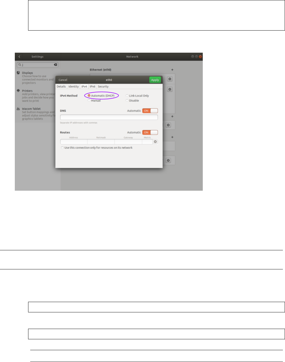
(continued from previous page)
inet 172.16.79.232/24 brd 172.16.79.255 scope global wlan0
valid_lft forever preferred_lft forever
inet6 fe80::250:56ff:fe28:7a8a/64 scope link
valid_lft forever preferred_lft forever
ViaGUI The image below illustrates how to se the interface to Automatic (DHCP) mode using the graph-
ical user interface.
16.4.7 Setting the Host InterfacetoStaticIP
Use this to set your interface to be assigned a static IPv4 address. This is useful for controlling the IP
address that the sensor will be sending data to.
Note: It is recommended that you unplug the cable from the interface prior to making changes to the
interface.
ViaCommandLine
Command
nmcli con modify [interface_name] ipv4.method manual ipv4.addresses [ip_address]
Example with interface name eth0 and IPv4 address 192.0.2.1/24.
username@ubuntu:~$ nmcli con modify eth0 ipv4.method manual ipv4.addresses 192.0.2.1/24
Note: The /24 is shorthand for Subnet Mask = 255.255.255.0
111

Response blank, however you can verify the change has been made with the ip addr command.
The inet line for the interface eth0 will show the static IPv4 address. e.g. 192.0.2.1
1: lo: <LOOPBACK,UP,LOWER_UP> mtu 65536 qdisc noqueue state UNKNOWN group default qlen 1000
link/loopback 00:00:00:00:00:00 brd 00:00:00:00:00:00
inet 127.0.0.1/8 scope host lo
valid_lft forever preferred_lft forever
inet6 ::1/128 scope host
valid_lft forever preferred_lft forever
2: eth0: <BROADCAST,MULTICAST,UP,LOWER_UP> mtu 1500 qdisc fq_codel state UP group default qlen
,→1000
link/ether 00:0c:29:2b:cc:48 brd ff:ff:ff:ff:ff:ff
inet 192.0.2.1/24 brd 192.0.2.255 scope global noprefixroute eth0
valid_lft forever preferred_lft forever
inet6 fe80::be9f:d2a4:4451:3dfe/64 scope link noprefixroute
valid_lft forever preferred_lft forever
3: wlan0: <BROADCAST,MULTICAST,UP,LOWER_UP> mtu 1500 qdisc fq_codel state UP group default qlen
,→1000
link/ether 00:50:56:28:7a:8a brd ff:ff:ff:ff:ff:ff
inet 172.16.79.232/24 brd 172.16.79.255 scope global wlan0
valid_lft forever preferred_lft forever
inet6 fe80::250:56ff:fe28:7a8a/64 scope link
valid_lft forever preferred_lft forever
ViaGUI The image below illustrates how to se the interface to Manual (static) mode using the graph-
ical user interface.
112

16.4.8 FindingaSensorwithmDNSService Discovery
The sensor announces its presence on the network using Multicast Domain Name Service (mDNS) with
a service type named _roger._tcp. You can use service discovery tools such as avahi-browse (Linux) to
find all sensors connected to the network.
1. Find all sensors and their associated service text which includes the sensor IPv4 address using
avahi-browse and the sensor service type _roger._tcp.
Command
avahi-browse -lrt [service type]
Example
username@ubuntu:~$ avahi-browse -lrt _roger._tcp
Response
+ eth0 IPv6 Ouster Sensor 991234567890 _roger._tcp local
+ eth0 IPv4 Ouster Sensor 991234567890 _roger._tcp local
= eth0 IPv6 Ouster Sensor 991234567890 _roger._tcp local
hostname = [os-991234567890.local]
address = [fe80::be0f:a7ff:fe00:1852]
port = [7501]
txt = ["fw=ousteros-image-prod-aries-v2.0.0-20200417193957" "sn=99201000067
8" "pn=840-102145-B"]
= eth0 IPv4 Ouster Sensor 991234567890 _roger._tcp local
hostname = [os-991234567890.local]
address = []
port = [7501]
txt = ["fw=ousteros-image-prod-aries-v2.0.0-20200417193957" "sn= 991234567890"
,→"pn=840-102145-B"]
Note: In this example, your sensor IPv4 address is determined to be 169.254.0.123.
113

17 Updating Firmware
Sensor firmware can be updated with an Ouster-provided firmware file from
www.ouster.com/resources (or directly from the deployment engineering team) by accessing
the sensor over http - e.g., http://os-991900123456.local/ and uploading the file as prompted.
Figure17.1: Uploading a new firmware image onto the sensor
Always check your firmware version before attempting an update. Only update to a equal or higher
version number.
17.1 Downgrading Firmware
Do not roll back firmware to lower numbered versions without having been instructed to do so by
Ouster. If you do, your sensor may experience issues. If your sensor is experiencing startup issue
upon downgrading from v2.0.0, reset the on-sensor configuration by using the Reset Configuration
button on Sensor Homepage.
114

18 Firmware Changelog
→
Version v2.0.0
Date 2020-11-20
Added
Add in azimuth_window config parameter documentation.
Add new TCP command get_lidar_data_format for information on the structure of a lidar
packet.
Add new key lidar_origin_to_beam_origin_mm to TCP command get_lidar_data_format for in-
formation on the structure of a lidar packet.
Add config parameters phase_lock_enable and phase_lock_offset to control motor phase
locking.
Add in new WARMUP sensor status to inform when sensor is in warmup state in cold tem-
perature startup.
Add STANDBY status from get_sensor_info when auto_start_flag = 0.
Add TCP command save_config_params to ultimately replace deprecated command
write_config_txt.
Add config parameter operating_mode which mirrors deprecated config parameter
auto_start_flag.
Add config parameter udp_dest which mirrors deprecated config parameter udp_ip.
Add alerts for errors related to motor phase locking.
Add alert for invalid user config params.
Add watchdog alerts for bad lidar data.
Add watchdog alerts for sync pulse or NMEA lock lost.
Add in part number compatibility for new and upcoming top-level sensor parts.
Removed
Remove deprecated TCP command set_udp_ip.
Changed
UDP packet size matches the number of channels on the sensor now (i.e. Gen 1 OS1-16 and
Gen 1 OS1-32 have smaller packet lengths).
TCP command get_beam_intrinsics now returns: 1) lidar_origin_to_beam_origin_mm, dis-
tance between the lidar origin and the beam origin in millimeters; and 2) beam altitude
and azimuth angle arrays with padded zeros removed.
azimuth_window parameter now in terms of millidegrees and implemented CCW in the Lidar
Coordinate Frame.
115

Updated on-sensor documentation to include TCP and HTTP API Guide only.
bit_count_unfiltered parameter replaces the misspelled bit_count_unfilterd parameter.
Diagnostics tab on sensor homepage now provides diagnostics info in single button.
Fixed
Reset Configuration button from Sensor Homepage (also DELETE sensor/config) now resets
PTP profile.
Added default route for static IPv4 override to fix multicast source addressing.
Corrected NMEA message decoding (date calculation on leap years).
Updated NMEA module to decode timestamp fields with decimal and up to 6 decimal char-
acters.
Fixed timestamp issue in TIME_FROM_PTP_1588 mode where time will jump 1 second backwards
for a single timestamp.
Fixed issue where sync_pulse_out signal was being driven while multipurpose_io was config-
ured as an input.
116
