
1
AVer Information Inc. Support Guide – AVer Pro-AV Camera (Updated 7/28/2021)
AVer Pro-AV Camera Control using
Visca over IP UDP and RS-232 commands
July 2021
Steps to verify the Aver PTZ310/PTZ330, TR530/320 and TR311HN / TR311 / TR313 / TR331 /
TR333 cameras can be controlled with Visca commands, UDP-IP and RS-232.
Visca over IP offers the ability to send several different control commands over a network (RJ45)
connection, without the need to add additional cabling.
The AVer CL01 Camera controller can control up to 255 separate cameras on the same subnet using
the Visca over IP protocol.
AVer has high quality image Cameras (TR311 / TR530 / PTZ330) that will integrate with these
workflows for peak performance and ease of use. We will show the configuration process for the
PTZ310/330, TR310/333, and TR530/320 Cameras using the Visca Over IP protocol.
There are several 3
rd
party controllers availble that integrate with the AVer Pro-AV cameras, Crestron,
Extron, QSC, Altona, RTI, to name a few. In this document we will discuss how to test the basic
controls via software should there be an issue where the before mentioned controllers are not
working as expected.
There are some pre-requisites for this to happen, see below.

2
AVer Information Inc. Support Guide – AVer Pro-AV Camera (Updated 7/28/2021)
Hercules Software
In order to verify “network” connectivity and control at a basic level, there is a “free” software
available (Windows) for use to test the Visca over IP command strings. This is a valuable tool in
order to “bypass” any hardware issues or programming issues from the devices being used.
It can be found here:
https://www.hw-group.com/software/hercules-setup-utility

3
AVer Information Inc. Support Guide – AVer Pro-AV Camera (Updated 7/28/2021)
Network Connection
The AVer cameras can be connected in one of several different ways, one of those is to connect the
cameras via network, using a good quality Cat5E (or better) network cable to a Gigabit network
switch.
*Note: Some of our cameras do support PoE+.
PTZ310/N and PTZ330/N require 25watts per LAN port
TR311/311HN/313/331/333 require 18 watts per LAN port.
Here is a typical camera network connection diagram.
In order for the AVer CL01 to communicate to the cameras via Visca Over IP, set the camera Protocol
to SonyVisca, selectable via the CL01 menu.
*Note: For more detailed information on the CL01 setup and configuration, refer to the CL01
Camera Controller Connection Guide or User Manual.
https://www.averusa.com/pro-av/support/
Network Ports
In order to check camera settings and camera control via a Chrome or IE-11 browser, verify the
following ports are open/available.
VISCA Control port: 52381 Internet protocol: IPv4
CGI port: 80 Transport protocol: UDP
RTSP port: 554

4
AVer Information Inc. Support Guide – AVer Pro-AV Camera (Updated 7/28/2021)
AVer PTZ310 / PTZ330 Camera Setup
The AVer PTZ310/330(N) offer exceptional optical quality up to 1080p/60 video standards, Quad
Output, NDI support, SRT Ready, SmartShoot motion tracking, and PoE+ support.
WebUI Network Connection:
1. Once all the equipment is connected, network IP’s have been assigned and configured, verify
you can gain access to the PTZ310/330 Camera by typing in the camera IP address in a
Chrome or IE-11 browser.
*Note: Edge, Safari and other browsers are not supported.
If this is the first time accessing the cameras WebUI, it will ask you for the default login
credentials, which are: “admin” and “admin”
It will then ask you to change the default values, PLEASE write that information down, and
then login with the NEW credentials.
2. Next, verify you can control the camera via the WebUI PTZ controls and can control the
Presets, Save, Load functions.

5
AVer Information Inc. Support Guide – AVer Pro-AV Camera (Updated 7/28/2021)
WebUI Network Connection (continued):
3. At this point you should have full control of the camera, ability to Save and Recall Presets, if
you do NOT have control, most likely the control port has been disabled/blocked. Verify
that port 52381 is open on the network.
4. Once the basic controls have been verified working from the WebUI of the camera, the next
step is to verify that sending Visca over IP commands work via the Hercules software.
Hercules Software Testing
In this next section we will discuss using the Hercules software in a very specific way to test the Visca
over IP commands are being recognized by the AVer camera.
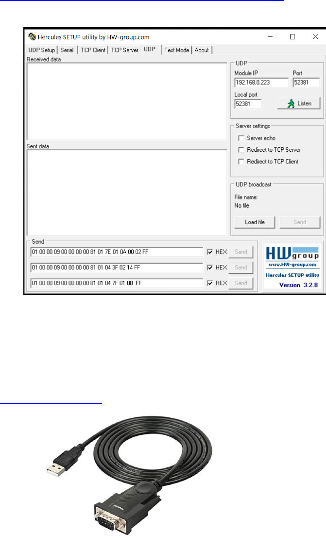
1. Open the Hercules software and select the UDP tab.
2. Next, enter the IP address of the camera as well as the Port number 52381.
3. Next, select “Listen”, you should see a green message appear, “UDP socket created”.

6
AVer Information Inc. Support Guide – AVer Pro-AV Camera (Updated 7/28/2021)
Hercules Software Testing (continued)
4. Next, we now want to send a basic command to the camera via Visca over IP.
For a complete list of commands, refer to the PTZ310/PTZ330/PTZ330N Control Codes
document.
https://www.averusa.com/pro-av/support/ look in the “Download” section.
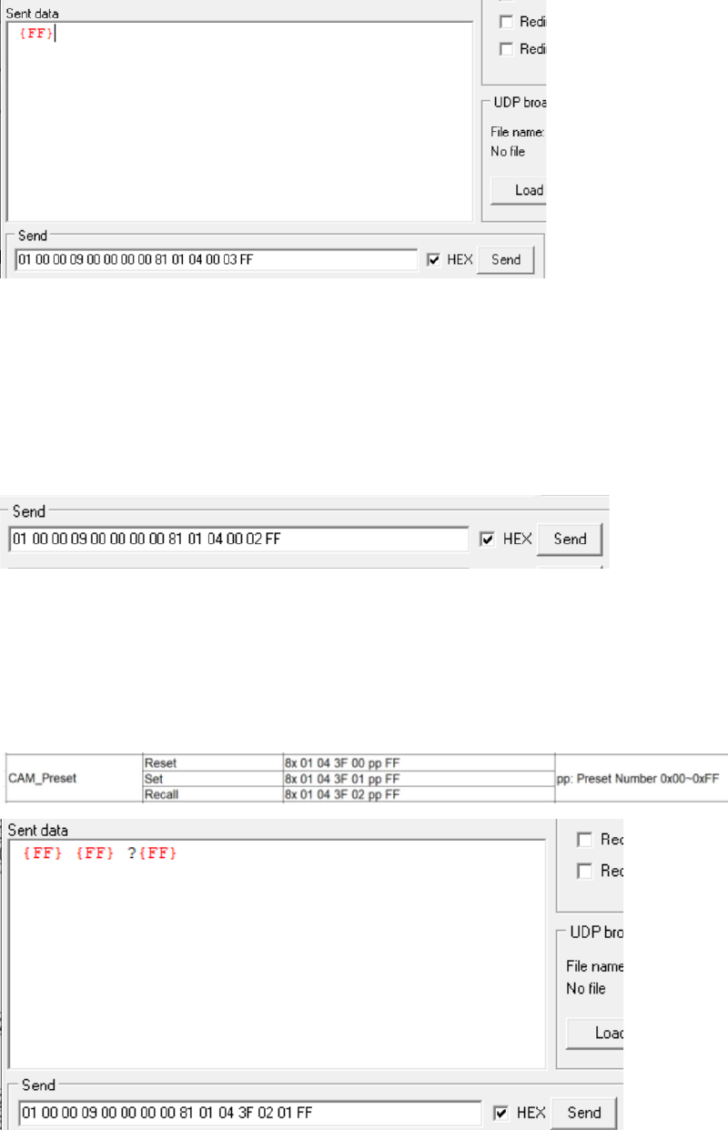
In this example we will send a Power Off command to the camera.
01 00 00 09 00 00 00 00 81 01 04 00 03 FF
5. Sending the Power Off command is pretty instant, the camera “may” go to a preset before
powering off, if it is configured that way, the end result should be that the camera has an
“Orange” LED on the front now and no video output.
6. Next, let us send a Power On command.
01 00 00 09 00 00 00 00 81 01 04 00 02 FF
The Orange LED should now start to blink for about 5 seconds, then the Power Up routine
kicks in. The PTZ310/330 camera will take about 45 seconds to boot up.

7
AVer Information Inc. Support Guide – AVer Pro-AV Camera (Updated 7/28/2021)
Hercules Software Testing (continued)
7. Next, let us test the Presets, Recall Preset #1
01 00 00 09 00 00 00 00 81 01 04 3F 02 01 FF
At this point, the camera should have moved to Preset #1 if it was configured.
8. If the commands being sent are NOT working, check the UDP ports.
In Windows open a “CMD” window and type in: netstat –a –p udp
Verify that Port 52381 is listed.
9. Verify/check your Network cable connections and how they are made, adhering to BICSI
standards. Typically, 568B wiring is the most common for network connections.
10. If you are using a Managed network switch, verify ports are opened.
11. This concludes the basic Visca over IP verification testing for the AVer PTZ310/330 cameras.

8
AVer Information Inc. Support Guide – AVer Pro-AV Camera (Updated 7/28/2021)
AVer TR311 / TR311HN / TR313 / TR331 / TR333 Camera Setup
The AVer TR311/333(N) cameras offer exceptional optical quality up to 4K UHD 2160p/60 video
standards, Quad Output, NDI HX support, SRT Ready, Advanced AI Auto Tracking, and PoE+ support.
WebUI Network Connection:
1. Once all the equipment is connected, network IP’s have been assigned and configured, verify
you can gain access to the TR311/333 Camera by typing in the IP address in a Chrome or IE-
11 browser.
*Note: Edge, Safari and other browsers are not supported.
If this is the first time accessing the cameras WebUI, it will ask you for the default login
credentials, which are: “admin” and “admin”
It will then ask you to change the default values, PLEASE write that information down, and
then login with the NEW credentials.
Video and Audio Settings, Video Mode Available Outputs

9
AVer Information Inc. Support Guide – AVer Pro-AV Camera (Updated 7/28/2021)
WebUI Network Connection (continued):
2. Next, verify you can control the camera via the WebUI PTZ controls and can control the
Presets, Save, Load functions.
3. At this point you should have full control of the camera, ability to Save and Recall Presets, if
you do NOT have control, most likely the control port has been disabled/blocked. Verify
that port 52381 is open on the network.
4. Once the basic controls have been verified working from the WebUI of the camera, the next
step is to verify the sending of Visca over IP commands work via the Hercules software.

10
AVer Information Inc. Support Guide – AVer Pro-AV Camera (Updated 7/28/2021)
Hercules Software Testing
In this next section we will discuss using the Hercules software in a very specific way to test the Visca
over IP commands are being recognized by the AVer camera.
1. Open the Hercules software and select the UDP tab.
2. Next, enter the IP address of the camera as well as the Local/Port number 52381.
3. Next, select “Listen”, you should see a green message appear, “UDP socket created”.
4. Next, we now want to send a basic command to the camera via Visca over IP.
For a complete list of commands, refer to the TR310/311HN/313/331/333 Control Codes
document.
https://www.averusa.com/pro-av/support/ look in the “Download” section.
In this example we will send a Power Off command to the camera.
01 00 00 09 00 00 00 00 81 01 04 00 03 FF
11
AVer Information Inc. Support Guide – AVer Pro-AV Camera (Updated 7/28/2021)
Hercules Software Testing (continued)
5. Sending the Power Off command is pretty instant, the camera “may” go to a preset before
powering off, if it is configured that way, the end result should be that the camera has an
“Orange” LED on the front now and no video output.
6. Next, let us send a Power On command.
01 00 00 09 00 00 00 00 81 01 04 00 02 FF
The Orange LED should now start to blink, then the Power Up routine kicks in. The
TR311/333 camera will take about 1 minute to completely boot up.
7. Next, let us test the Presets, Recall Preset #1
01 00 00 09 00 00 00 00 81 01 04 3F 02 01 FF
At this point, the camera should have moved to Preset #1 if it was configured.

12
AVer Information Inc. Support Guide – AVer Pro-AV Camera (Updated 7/28/2021)
Hercules Software Testing (continued)
Switch Command, to “switch” who the camera is tracking, 2 people in the shot
Tracking Enable
Tracking Disable
8. If the commands being sent are NOT working, check the UDP ports.
In Windows, open a “CMD” window and type in: netstat –a –p udp
Verify that Port 52381 is listed.
9. Verify/check your Network cable connections and how they are made, adhering to BICSI
standards. Typically, 568B wiring is the most common for network connections.
10. If you are using a Managed network switch, verify ports are opened.
11. This concludes the basic Visca over IP verification testing for the AVer TR311/333 cameras.

13
AVer Information Inc. Support Guide – AVer Pro-AV Camera (Updated 7/28/2021)
AVer TR530 / TR320 Camera Setup
The AVer TR530 / TR320 cameras offer exceptional optical quality up to 1080p/60 video standards,
Quad Output, (2) SDI Outputs, HDMI Output, Auto Tracking, and RTSP output.
WebUI Network Connection:
1. Once all the equipment is connected, network IP’s have been assigned and configured, verify
you can gain access to the TR530/320 Camera by typing in the IP address in a Chrome or IE-
11 browser.
*Note: Edge, Safari and other browsers are not supported.
If this is the first time accessing the cameras WebUI, it will ask you for the default login
password, which is: “admin”
It “may” ask you to change the default values, PLEASE write that information down, and then
login with the NEW credentials.
2. Next, verify you can control the camera via the WebUI PTZ controls and can control the
Presets, Save, Load functions.

14
AVer Information Inc. Support Guide – AVer Pro-AV Camera (Updated 7/28/2021)
WebUI Network Connection (continued):
3. Next, with the TR530 / TR320 camera we must verify that the camera has been configured
for use with Visca Over IP, this is done by checking the Advanced Setting tab.
Make sure it has been ENABLED.
4. Next, at this point you should have control of the camera, ability to Save and Recall Presets, if
you do NOT have control, most likely the control port has been disabled/blocked. Verify that
port 52381 is open on the network.
5. Once the basic controls have been verified working from the WebUI of the camera, the next
step is to verify that sending Visca over IP commands work via the Hercules software.

15
AVer Information Inc. Support Guide – AVer Pro-AV Camera (Updated 7/28/2021)
Hercules Software Testing
In this next section we will discuss using the Hercules software in a very specific way to test the Visca
over IP commands are being recognized by the AVer camera.
1. Open the Hercules software and select the UDP tab.
2. Next, enter the IP address of the camera as well as the Port number 52381.
3. Next, select “Listen”, you should see a green message appear, “UDP socket created”.
4. Next, we now want to send a basic command to the camera via Visca over IP.
For a complete list of commands, refer to the TR530 / TR320 Control Codes document.
https://www.averusa.com/pro-av/support/ look in the “Download” section.
NOTE:
In the previous camera examples, we showed Power On/OFF, the TR530/320 camera does
NOT support the Power ON command via Visca OVER IP. It does; however, work when
connected via RS-232.

16
AVer Information Inc. Support Guide – AVer Pro-AV Camera (Updated 7/28/2021)
Hercules Software Testing (continued)
In this example we will send a Camera Menu command to the camera.
01 00 00 09 00 00 00 00 81 01 06 06 10 FF
5. You should see the OSD camera Menu display on the HDMI/SDI output of the camera.
6. Sending the command again will then remove the OSD camera Menu.
7. Next, let us test the Presets, Recall Preset #1
01 00 00 09 00 00 00 00 81 01 04 3F 02 01 FF
At this point, the camera should have moved to Preset #1 if it was configured.

17
AVer Information Inc. Support Guide – AVer Pro-AV Camera (Updated 7/28/2021)
Hercules Software Testing (continued)
8. If the commands being sent are NOT working, check the UDP ports.
In Windows, open a “CMD” window and type in: netstat –a –p udp
Verify that Port 52381 is listed.
9. Verify/check your Network cable connections and how they are made adhering to BICSI
standards. Typically, 568B wiring is the most common for network connections.
10. If you are using a Managed network switch, verify ports are opened.
11. This concludes the basic Visca over IP verification testing for the AVer PTZ310/330 cameras.
Crestron Example:
I had captured some Crestron control line syntax from another project, they were using Toolbox, this
example shows Recalling Preset 5 on a TR530 camera.

18
AVer Information Inc. Support Guide – AVer Pro-AV Camera (Updated 7/28/2021)
AVer Pro-AV RS-232 Control
Using the RS-232 and RS-422 control protocol offers the ability to send several different control
commands over a dedicated control cable without the need to be concerned about Network
firewalls, Ports used, or adding additional equipment like a network switch and Cat5E cabling.
With the RS232/RS422 serial connection, there are different protocols that can be used, below is a
summary of the protocols.
VISCA: Up to 7 cameras can be addressed.
Pelco-P: Up to 32 cameras can be addressed.
Pelco-D: Up to 256 cameras can be addressed, (Address 0-255).
VISCA over IP: Up to 256 cameras can be addressed on the same network subnet.
The AVer CL01 Camera controller can control up to 255 separate cameras on the same subnet using
the Visca over IP protocol. Looking at the information above, using VISCA control, we can only
control up to 7 cameras.
AVer has high quality image Cameras (TR311 / TR530 / PTZ330) that will integrate with these
workflows for peak performance and ease of use. We will show the configuration process for the
PTZ310/330, TR310/333, and TR530/320 Cameras using the Visca protocol.
There are several 3
rd
party controllers availble that integrate with the AVer Pro-AV cameras, Crestron,
Extron, QSC, Altona, RTI, to name a few. In this document we will discuss how to test the basic
controls via software should there be an issue where the before mentioned controllers are not
working as expected.
There are some pre-requisites for this to happen, see below.
19
AVer Information Inc. Support Guide – AVer Pro-AV Camera (Updated 7/28/2021)
Hercules Software
In order to verify “RS232 control” connectivity and control at a basic level, there is a “free” software
available (Windows) to test the Visca-RS232 command strings. This is a valuable tool in order to
“bypass” any hardware issues or programming issues from the devices being used.
It can be found here:
https://www.hw-group.com/software/hercules-setup-utility
RS-232 Adaptor
If not already in your toolkit, purchase an RS-232 (9-Pin) to USB cable, it will be needed to test the
RS-232 connection and commands.
USB to Serial Adaptor
Once connected, it should show up in your “Device Manager” and have a COM Port associated with
it, i.e., COM2.

20
AVer Information Inc. Support Guide – AVer Pro-AV Camera (Updated 7/28/2021)
PTZ310 / PTZ330 RS-232 Connection
The AVer cameras can be connected in one of several different ways, one of those is to connect the
cameras via a dedicated control cable.
Here is a typical camera RS-232 connection diagram.
For the AVer CL01 to communicate to the cameras via Visca, set the camera Protocol to Visca and
configure the correct Address of the camera via the CL01 Sub-Menu, selectable via the CL01 menu.
*Note: For more detailed information on the CL01 setup and configuration, refer to the CL01
Camera Controller Connection Guide or User Manual.
https://www.averusa.com/pro-av/support/

21
AVer Information Inc. Support Guide – AVer Pro-AV Camera (Updated 7/28/2021)
AVer PTZ310 / PTZ330 Camera Setup
The AVer PTZ310/330(N) offer exceptional optical quality up to 1080p/60 video standards, Quad
Output, NDI support, SRT Ready, SmartShoot motion tracking, and PoE+ support.
OSD Menu
Connect the HDMI or SDI output of the camera to a monitor to gain access to the OSD menu.
From here configure the camera to suite your environment, in this example we will be using Address
#1 for setting up CAM 1.
Verify the following via the OSD menu:
1. Control Type: RS232
2. Protocol: VISCA
3. Camera Address: 1, or whatever you want it to be (1 – 7).
4. Baude Rate: 9600, to start with.
5. If using a CL01 controller, match the CL01 with the camera settings.

22
AVer Information Inc. Support Guide – AVer Pro-AV Camera (Updated 7/28/2021)
RS-232 Connection:
*Note: An RS232 Y-cable splitter (In/Out) is used to “daisy chain” the cameras together when
connecting more than (1) camera.
Part Number: PTRSINOUT, [Din9-M to (2) Din8-F]
There is an RS232 accessories cable used with the PTZ cameras to connect its MiniDin9
connection using a Mini DIN8 to 9Pin DSub connector.
Part Number: PTDIN8PT1, Din8-M to 9-Pin DSub-F
Below is a connection diagram of the AVer PTZ series of cameras connected via RS-232 cabling and a
PC using a USB to Serial converter (DSub9-M).

23
AVer Information Inc. Support Guide – AVer Pro-AV Camera (Updated 7/28/2021)
Hercules Software Testing
In this next section we will discuss using the Hercules software in a very specific way to test the Visca
commands are being recognized by the AVer camera.
1. Open the Hercules software and select the Serial tab.
2. Next, configure the COM Port to match what is being used by your computer, i.e., COM2.
3. Next, select “Open”, you should see a green message appear, “Serial Port socket created”.
4. Next, we now want to send a basic command to the camera via Visca over IP.
For a complete list of commands, refer to the PTZ310/PTZ330/PTZ330N Control Codes
document.
https://www.averusa.com/pro-av/support/ look in the “Download” section.

24
AVer Information Inc. Support Guide – AVer Pro-AV Camera (Updated 7/28/2021)
Hercules Software Testing (continued)
5. In this example we will send a Power Off command to the camera.
01 00 00 09 00 00 00 00 81 01 04 00 03 FF
Sending the Power Off command is instant, the camera “may” go to a preset before
powering off, if it is configured that way, the end result should be that the camera has an
“Orange” LED on the front now and no video output.
6. Next, send a Power On command.
01 00 00 09 00 00 00 00 81 01 04 00 02 FF
The Orange LED should now start to blink for about 5 seconds, then the Power Up routine
kicks in. The PTZ310/330 camera will take about 45 seconds to boot up.
7. Next, let us test the Presets, Recall Preset #1
01 00 00 09 00 00 00 00 81 01 04 3F 02 01 FF

25
AVer Information Inc. Support Guide – AVer Pro-AV Camera (Updated 7/28/2021)
Hercules Software Testing (continued)
At this point, the camera should have moved to Preset #1 if it was configured.
8. If the commands being sent are NOT working, check the COM port setup.
• Verify that the COM Port # listed in Windows is the one being used in Hercules.
• Verify/check your cable connections and they are securely in place.
9. This concludes the basic Visca RS-232 verification testing for the AVer PTZ310/330 cameras.

26
AVer Information Inc. Support Guide – AVer Pro-AV Camera (Updated 7/28/2021)
AVer TR311 / TR311HN / TR313 / TR331 Camera Setup
The AVer TR311/333(N) cameras offer exceptional optical quality up to 4K UHD 2160p/60 video
standards, Quad Output, NDI HX support, SRT Ready, Advanced AI Auto Tracking, and PoE+ support.
OSD Menu
Connect the HDMI or SDI output of the camera to a monitor to gain access to the OSD menu.
From here configure the camera to suite your environment, in this example we will be using Address
#1 for setting up CAM 1.
Verify the following via the OSD menu:
1. Control Type: RS232
2. Protocol: VISCA
3. Camera Address: 1, or whatever you want it to be (1 – 7).
4. Baude Rate: 9600, to start with.
5. If using a CL01 controller, match the CL01 with the camera settings.

27
AVer Information Inc. Support Guide – AVer Pro-AV Camera (Updated 7/28/2021)
RS-232 Connection:
*Note: An RS232 Y-cable splitter (In/Out) is used to “daisy chain” the cameras together when
connecting more than (1) camera to control.
Part Number: PTRSINOUT, [Din9-M to (2) Din8-F]
There is an RS232 accessories cable used with the PTZ cameras to connect its MiniDin9
connection using a Mini DIN8 to 9Pin DSub connector.
Part Number: PTDIN8PT1, Din8-M to 9Pin DSub-F
Below is a connection diagram of the AVer PTZ series of cameras connected via RS-232 cabling and a
PC using a USB to Serial converter (DSub9-M).

28
AVer Information Inc. Support Guide – AVer Pro-AV Camera (Updated 7/28/2021)
Hercules Software Testing
In this next section we will discuss using the Hercules software in a very specific way to test the Visca
commands are being recognized by the AVer camera.
1. Open the Hercules software and select the Serial tab.
2. Next, configure the COM Port # to match what is being used by your computer, i.e., COM2.
3. Next, select “Open”, you should see a green message appear, “Serial Port socket created”.
4. Next, we now want to send a basic command to the camera via Visca over IP.
For a complete list of commands, refer to the TR311/311HN/313/331/333 Control Codes
document.
https://www.averusa.com/pro-av/support/ look in the “Download” section.

29
AVer Information Inc. Support Guide – AVer Pro-AV Camera (Updated 7/28/2021)
Hercules Software Testing (continued)
5. In this example we will send a Power Off command to the camera.
01 00 00 09 00 00 00 00 81 01 04 00 03 FF
Sending the Power Off command is instant, the camera “may” go to a preset before
powering off, if it is configured that way, the end result should be that the camera has an
“Orange” LED on the front now and no video output.
6. Next, send a Power On command.
01 00 00 09 00 00 00 00 81 01 04 00 02 FF
The Orange LED should now start to blink for about 5 seconds, then the Power Up routine
kicks in. The TR311/331 cameras will take about 60 seconds to boot up.
7. Next, let us test the Presets, Recall Preset #1
01 00 00 09 00 00 00 00 81 01 04 3F 02 01 FF

30
AVer Information Inc. Support Guide – AVer Pro-AV Camera (Updated 7/28/2021)
Hercules Software Testing (continued)
At this point, the camera should have moved to Preset #1 if it was configured.
8. Additional TR311/331 RS-232 commands to try:
Switch Command, to “switch” who the camera is tracking, 2 people in the shot
Tracking Enable
Tracking Disable
9. If the commands being sent are NOT working, check the COM port setup.
• Verify that the COM Port # listed in Windows is the one being used in Hercules.
• Verify/check your cable connections and they are securely in place.
10. This concludes the basic Visca RS-232 verification testing for the AVer TR311/331 cameras.

31
AVer Information Inc. Support Guide – AVer Pro-AV Camera (Updated 7/28/2021)
AVer TR530 / TR320 Camera Setup
The AVer TR530 / TR320 cameras offer exceptional optical quality up to 1080p/60 video standards,
Quad Output, (2) SDI Outputs, HDMI Output, RTSP output, and Auto Tracking.
OSD Menu
Connect the HDMI or SDI output of the camera to a monitor to gain access to the OSD menu.
From here configure the camera to suite your environment, in this example we will be using Address
#1 for setting up CAM 1.
Verify the following via the OSD menu:
1. RS232 Protocol: VISCA
2. Address: 1, or whatever you want it to be (1 – 8).
4. Baude Rate: 9600, to start with.
5. If using a CL01 controller, match the CL01 with the camera settings.

32
AVer Information Inc. Support Guide – AVer Pro-AV Camera (Updated 7/28/2021)
TR530 / TR320 WebUI Network Connection
If the TR530 / TR320 camera is connected via the network, you can gain access to the camera’s
WebUI by typing in the IP address in a Chrome or IE-11 browser.
*Note: Edge, Safari, and other browsers are not supported.
If this is the first time accessing the cameras WebUI, it will ask you for the default login
password, which is: “admin”
It “may” ask you to change the default values, PLEASE write that information down, and then
login with the NEW credentials.
1. Next, go to the Advanced settings, you can verify the control settings there as well.
2. Once the basic controls have been verified working from the WebUI of the camera, the next
step is to verify that sending RS-232 Visca commands via the Hercules software.

33
AVer Information Inc. Support Guide – AVer Pro-AV Camera (Updated 7/28/2021)
RS-232 Connection:
*Note: An RS232 Y-cable splitter (In/Out) could be used to “daisy chain” the cameras together when
connecting more than (1) camera to control.
AVer Pro-AV does not provide this cable, it would need to be purchased from another source.
Din6-M to (2) DIN6-F
There is an RS232 accessories cable used with the PTZ cameras to connect its MiniDin6
connection using a Mini DIN6 to 9Pin DSub-F connector.
Part Number: COMVCC232, Din6-M to 9Pin DSub-F
Below is a connection diagram of the AVer TR530/320 series of cameras connected via RS-232
cabling and a PC using a USB to Serial converter (DSub 9).

34
AVer Information Inc. Support Guide – AVer Pro-AV Camera (Updated 7/28/2021)
Hercules Software Testing
In this next section we will discuss using the Hercules software in a very specific way to test the Visca
over IP commands are being recognized by the AVer camera.
1. Open the Hercules software and select the Serial tab.
2. Next, configure the COM Port # to match what is being used by your computer, i.e., COM2.
3. Next, select “Open”, you should see a green message appear, “Serial Port socket created”.
4. Next, we now want to send a basic command to the camera via Visca over IP.
For a complete list of commands, refer to the TR530 / TR320 Control Codes document.
https://www.averusa.com/pro-av/support/ look in the “Download” section.
NOTE:
In the previous camera examples, we showed Power On/OFF, the TR530/320 camera does
NOT support the Power ON command via Visca OVER IP. It does; however, work when
connected via RS-232.

35
AVer Information Inc. Support Guide – AVer Pro-AV Camera (Updated 7/28/2021)
Hercules Software Testing (continued)
5. In this example we will send a Camera Menu command to the camera.
01 00 00 09 00 00 00 00 81 01 06 06 10 FF
6. You should see the OSD camera Menu display on the HDMI/SDI output of the camera.
7. Sending the command again will then remove the OSD camera Menu.
8. Next, let us test the Presets, Recall Preset #1
01 00 00 09 00 00 00 00 81 01 04 3F 02 01 FF
At this point, the camera should have moved to Preset #1 if it was configured.

36
AVer Information Inc. Support Guide – AVer Pro-AV Camera (Updated 7/28/2021)
Hercules Software Testing (continued)
9. Next, let us test the Power OFF command
01 00 00 09 00 00 00 00 81 01 04 00 03 FF
The TR530/320 can take up to 10seconds before you see the LED light begin to blink, then
turn Red.
10. Next, let us test the Power ON command
01 00 00 09 00 00 00 00 81 01 04 00 02 FF
Again, it could take up to 10 seconds to be recognized, the LED should start blinking.
The TR530/320 camera takes about 60 seconds to fully boot up.
11. If the commands being sent are NOT working, check the COM port setup.
• Verify that the COM Port # listed in Windows is the one being used in Hercules.
• Verify/check your cable connections and they are securely in place.
12. This concludes the basic Visca RS-232 verification testing for the AVer TR530/320 cameras.
AVer CL01 Camera Controller Pinout
RS-232
9pin DSub-M
Pin 2 – RXD
Pin 3 – TXD
Pin 5 – GND/Shield

37
AVer Information Inc. Support Guide – AVer Pro-AV Camera (Updated 7/28/2021)
RS-422 AVer TR311 to TR331 and PTZ310 / PTZ330 Camera Setup
The AVer cameras can also be controlled via RS-422, the following will cover the RS-422 hardware
connections. The VISCA tests will be the same as mentioned before using the Hercules software.
OSD Menu
Connect the HDMI or SDI output of the camera to a monitor to gain access to the OSD menu.
From here configure the camera to suite your environment, in this example we will be using Address
#1 for setting up CAM 1.
Verify the following via the OSD menu:
1. Control Type: RS422
2. Protocol: VISCA
3. Camera Address: 1, or whatever you want it to be (1 – 7).
4. Baude Rate: 9600, to start with.
5. When using a CL01 controller, match the CL01 with the camera settings.
CL01 RS422 Connection

38
AVer Information Inc. Support Guide – AVer Pro-AV Camera (Updated 7/28/2021)
RS-422 Connection:
For the RS-422 connection to the camera, an RJ-45 cable is needed using Cat5E cable, 8-Pin Male
connector on the camera side, and open wires on the CL01 side.
Below is a connection diagram of the AVer TR311 and PTZ310 series of cameras connected via
RS-422 cabling and the AVer CL01 4-pin Phoenix connector.
Multiple Camera RS-422 Connection

39
AVer Information Inc. Support Guide – AVer Pro-AV Camera (Updated 7/28/2021)
Multiple Camera RS-422 Connection (continued)

40
AVer Information Inc. Support Guide – AVer Pro-AV Camera (Updated 7/28/2021)
AVer Pro-AV Cable Drawings

41
AVer Information Inc. Support Guide – AVer Pro-AV Camera (Updated 7/28/2021)
RS-232 Pro-AV Camera Control Diagrams

42
AVer Information Inc. Support Guide – AVer Pro-AV Camera (Updated 7/28/2021)
RS-232 Pro-AV Camera Control Diagrams (continued)

43
AVer Information Inc. Support Guide – AVer Pro-AV Camera (Updated 7/28/2021)
VISCA over IP Packets
If you are using a 3
rd
party controller, Crestron, Extron, QSC, Altona, etc. verify the command
structure you are using is correct for BOTH the controller and the camera.
VISCA over IP commands need to be sent in full packet order:
Packet header + VISCA command.
Let’s take PT_Up as an example.
The full command should be 01 00 00 09 00 00 00 00 81 01 06 01 08 08 03 01 ff.
RED part of command is for VISCA over IP packet header. BLUE part of command is
for VISCA command.
Also, after any pan tilt movement command is sent, it needs to send PT_Stop command to stop
movement, which should be 01 00 00 09 00 00 00 00 81 01 06 01 08 08 03 03 ff.
For the VISCA over IP header, the 3rd & 4th bytes of the header are important.
They indicate length of payload (VISCA command).
At this point, the value could be varying depending on what VISCA command is sent.
For example:
Inquiry (listed as “info”) - 01 00 00 05 00 00 00 00 81 09 00 02 FF
Settings (listed as “framing”) - 01 00 00 07 00 00 00 00 81 01 04 7D 00 00 FF
Command (movements) - 01 00 00 09 00 00 00 00 81 01 06 01 08 08 03 01 FF
