
“Mind the Gap” session
243
rd
AAS Meeting, 9 January 2024
UV CMOS Detectors for
CASTOR and Beyond
Chaz Shapiro
© 2023 California Institute of Technology. Government
sponsorship acknowledged.
JPL Collaborators:
John Hennessey, Michael Hoenk, April Jewell,
Todd Jones, Shouleh Nikzad
Thanks to Pat Côté (NRCC, CASTOR science PI)
for slide contributions

CASTOR
The Cosmological Advanced Survey Telescope for Optical and uv Research
CASTOR Mission Overview
Light-weighted Zerodur 1m primary mirror
Three Mirror Anastigmat with 0.25 deg
2
FoV
Active M2 for WFE compensation
Fine steering mirror for image stabilization
1063 kg spacecraft and 10 Gbps optical downlink
MAC200-small-SAT bus
800 km polar SSO for efficient surveys
Dichroic separation of wavebands
Optical coatings on all mirrors for red leak control
Minimum 5 year mission (Goal:10 years)
Combination of Legacy Surveys (64%), Guest Observer
programs (25%), Target-of-Opportunity programs (8%),
and calibration time (3%)
14 candidate Legacy Surveys advanced to SRL4 during
Phase 0
To be revisited once the partnership is finalized
“Our highest recommendation at the very large investments scale is for CASTOR,
an exciting mission with a broad and compelling science case, and which would be
Canada’s first marquee space astronomy mission.”
— Canadian Astronomy Long-Range Plan 2020
Focal planes
Acronym!

CASTOR
The Cosmological Advanced Survey Telescope for Optical and uv Research
Imaging and UV Spectroscopy
Wide-field UV/blue-optical imaging
3 x 310 Megapixel arrays sampled at 0.1”/pixel
Simultaneous imaging in three channels
Back-illuminated large-format CMOS detectors with ALD AR
coatings and 2D-doping
Two spectroscopic modes
Deployable grism (150-400nm, R~350) over full FOV
UVMOS with DMD selector (150-300nm, R~1000-2000) over
207” x 117” (offset from FOV)
Grism and UVMOS instruments make up roughly one third of the time
requested for legacy surveys
Grism spectroscopy is used in 6/14 surveys
UVMOS spectroscopy is used in 7/14 surveys
Spectroscopic science drivers include the progenitors of kilonovae, the
evolution of the cosmic web, AGN reverberation mapping, flare rates in
M dwarfs, the surface chemistry of Trans Neptunian Objects, and more
(Spectroscopic)
SN Type II
SN Type Ia

CASTOR detector requirements
• Low dark current < 0.01 e-/px/s
• Low read noise < 6 e- rms
• Low power dissipation
• Pixel pitch <= 10 µm
• Ability to do 10 Hz fine guiding on main array
without disrupting science integrations
• Large, buttable arrays to reduce chip gaps and
number of detectors
• Radiation hard
CMOS solution
• High UV QE 2D doping and AR-coating
Teledyne-e2v CIS301
9K x 8.6K pixels ; 10µm pitch
Teledyne-e2v CIS120
2K x 2K pixels ; 10µm pitch

~1 Gpx focal plane divided into 3
channels/bands
• Detector coatings chosen by
CASTOR to maximize in-band QE
for each channel
• Out-of-band light rejected by
dichroics and mirror coatings
Nominal bands with detector AR coatings
FUV
150-300
NUV
300-400
VIS
400-550

JPL Engagement in CASTOR
❑ CASTOR partners (NRCC, Honeywell, ABB) have
been working closely with JPL since 2017, with the
ultimate goal of securing a NASA partnership.
❑ Science JPL/IPAC scientists made key
contributions to the 2019 CASTOR Science
Maturation study, serving as co-leads on 7 of 8
science working groups for the Phase 0 study.
(POC: Jason Rhodes)
Technology JPL’s Advanced Detector group and
Teledyne-e2v have delivered 2D doped and AR
coated CIS120 prototypes to CSA as part of their
Space Technologies Development Program (POC:
Chaz Shapiro)
CIS120 wafer inspection
FUV coating models

2D-Doping: Expanding design space for UV missions of all sizes
• Detectors are the heart of an instrument, driving major mission design
trades: mass, power, optical configuration, observing strategy, cost
• Solid state detectors continue to grow in scale, sensitivity, and capability.
Choose from: CCD (incl. Skipper, EMCCD), CMOS, APD, SPAD...
• …but they are not natively UV-sensitive
• JPL’s 2D-doping process converts Si-based devices into UV detectors,
allowing UV missions to take full advantage of latest technologies. 2D-
doping and subsequent coatings:
• provide high, stable QE in UV
• are agnostic to device architecture – process on backside doesn’t “see” frontside
• allow QE to be tailored to required wavelength bands
• are radiation tolerant (Hoenk et al. 2014)

jpl.nasa.gov
• Precision coatings via Atomic Layer Deposition
• Single and Multilayer coatings can tailor response in and out of the desired
band.
• Coatings deposited on detector eliminate standalone filters and reduce optical
complexity.
Antireflection (AR) Coatings and Metal Dielectric Filters
(MDF) optimize QE
Jewell, et al., Proc. SPIE 8820 (2013) 88200Z
Nikzad, et al., Applied Optics, 51, (2012) 365
Solar blind MDF
Narrow band AR
Broadband AR
See talks by
April Jewell
&
John Hennessey!

The Future: Explorers and
Flagships
https://asd.gsfc.nasa.gov/luvoir/design/
Instrument Baseline Detector
High Definition Imager (HDI) Delta-doped CMOS array;
200-1100nm
Ultraviolet Multi-Object
Spectrograph (LUMOS)
Delta-doped CMOS array;
200-400nm (MCP 100-200)
Pollux (European Contribution) Delta-doped CCDs;
97-390nm
ECLIPS (Coronograph) Delta-doped EMCCD; 200-
525nm
https://www.jpl.nasa.gov/habex/
Instrument Baseline Detector
Workhorse Camera (HWC) Delta-doped CCD/CMOS;
150-950nm
UV Spectrometer Delta-doped EMCCD
(backup); 115-300nm
Coronograph Delta-doped EMCCD;
450-670nm
Starshade Delta-doped EMCCD;
200-450nm
LUVOIR
• 2D-doped detectors are baselined
or backups for several instruments
• Working with industry to develop
devices that meet challenging
requirements
• E.g. LUVOIR needs large, buttable
arrays with <7µm pixels and fast,
low noise readout.
(Some wavelength
ranges shown span
multiple channels)
LUVOIR & HabEx
Habitable Worlds Observatory!

Backup

Notional Schedule

CASTOR
The Cosmological Advanced Survey Telescope for Optical and uv Research
TDAMM Science with CASTOR UVMOS
Applications of intermediate-resolution UVMOS spectroscopy for
TDAMM science
Supernovae spectra: characterization of CSM and progenitor stars from
Fe II, Ni II and Mg II absorption depths, plus the height and slope of the
UV continuum
Spectroscopic follow up of kilonovae and other transients out to
distances of 500 Mpc
UV emission-line observations of tidal disruption events
Characterization of super-luminous and infant supernovae from UV
continuum measurements and equivalent widths for lines of ionized Si,
C, Mg and Ti between 220 and 270 nm

CASTOR
The Cosmological Advanced Survey Telescope for Optical and uv Research
Galaxies in the Cosmic Web with CASTOR
EAGLE simulation: McAlpine et al. (2016)
Grism and UVMOS slit-less grism spectra will capture
redshifts for 1000s of Lyman-α emitters (LAEs) and
Lyman Break Galaxies (LBGs) per pointing
CASTOR grism redshifts will trace the cosmic web to
z~3
This will allow us to study galaxy evolution in the full
range of cosmic environments to 11 Gyr before the
present

Partnerships and Collaborations
NASA Desired contribution: CASTOR’s three WFI cameras (see below). Additional contributions
are possible and welcome
UKSA Participation approved in Jan. 2023 through a new bilaterals program in space science
Contributions under discussion with CSA, including detector qualification, testing, electronics; cryo-
cooler; filters; coatings; secondary; data flows
Detector procurement discussions are ongoing, focusing on a separate UKSA funding stream
India/ISRO In December 2021, ISRO had expressed strong interest in a partnership
Expected contributions: launch, UVMOS, ground stations
A timely agreement could not be reached. CASTOR is now seeking other partners to provide these
items
Spain/France Strong interest in the UVMOS (formerly an Indian contribution).
South Korea Discussions underway

jpl.nasa.gov
The Silicon UV Problem
Passivation by 2D-Doping shrinks the dead layer
Hoenk et al., APL, 61 (1992) 1084
Nikzad et al., Proc. SPIE 4139 (2000) 250
2D-doping provides the maximum
possible QE, limited only by photon
transmission into the silicon.
“delta” doping =
Delta function profile
Dead layer
+
shallow absorption
= poor QE
jpl.nasa.gov
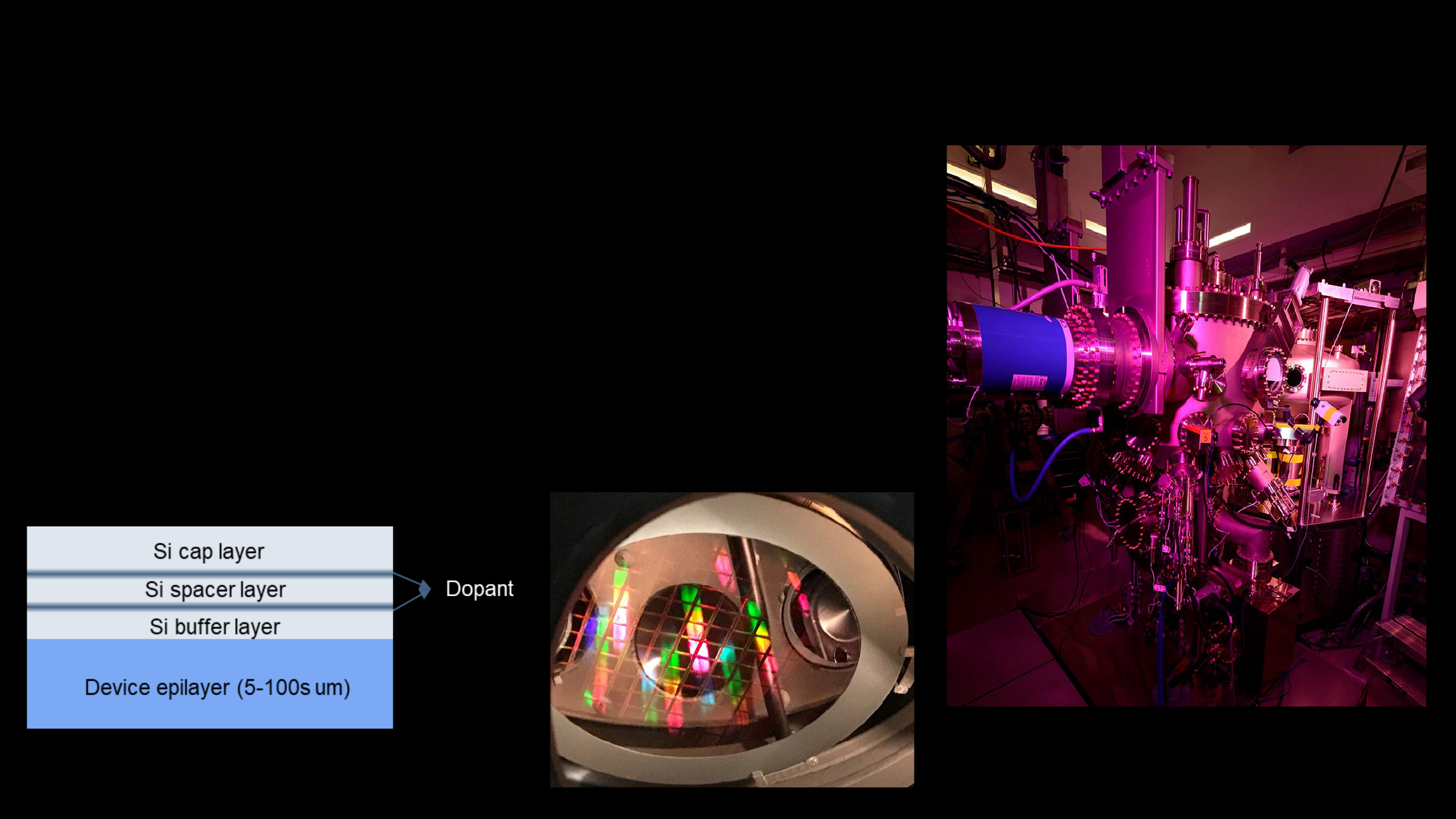
2D-doping Process: Molecular Beam Epitaxy (MBE)
• Device wafer (up to 8”) bonded to handle wafer to protect
frontside structures and add stability
• Backside surface is thinned to epitaxial Si layer
• New Si deposited by e-beam evaporation
• “Delta” layer of dopant added: P-type doping (B) or N-type (Sb)
• Additional Si cap added
• OR repeat for “superlattice” doping for extra stability
• Deposited silicon layers typically 1-3 nm
• Wafer is diced, devices are completed with packaging
Veeco Gen 200
Wafer in MBE
