
Minimum Design
Loads for Buildings
and Other Structures
This document uses both the
International System of Units (SI)
and customary units
ASCE STANDARD
ASCE/SEI
7–10

A S C E STA NDA RD ASCE/SEI 7-10
American Society of Civil Engineers
Minimum Design Loads
for Buildings and
Other Structures
This document uses both the International System of Units (SI)
and customary units.
PR_version_1.indd i 4/14/2010 1:40:42 PM

Library of Congress Cataloging-in-Publication Data
Minimum design loads for buildings and other structures.
p. cm.
“ASCE Standard ASCE/SEI 7-10.”
Includes bibliographical references and index.
ISBN 978-0-7844-1085-1 (alk. paper)
1. Structural engineering–Standards–United States.
2. Buildings–Standards–United States. 3. Strains and stresses.
4. Standards, Engineering–United States. I. American Society of
Civil Engineers.
TH851.M56 2010
624.1′75021873—dc22
2010011011
Published by American Society of Civil Engineers
1801 Alexander Bell Drive
Reston, Virginia 20191
www.pubs.asce.org
This standard was developed by a consensus standards development
process which has been accredited by the American National Standards
Institute (ANSI). Accreditation by ANSI, a voluntary accreditation
body representing public and private sector standards development
organizations in the U.S. and abroad, signifi es that the standards devel-
opment process used by ASCE has met the ANSI requirements for
openness, balance, consensus, and due process.
While ASCE’s process is designed to promote standards that refl ect a
fair and reasoned consensus among all interested participants, while
preserving the public health, safety, and welfare that is paramount to
its mission, it has not made an independent assessment of and does
not warrant the accuracy, completeness, suitability, or utility of any
information, apparatus, product, or process discussed herein. ASCE
does not intend, nor should anyone interpret, ASCE’s standards to
replace the sound judgment of a competent professional, having
knowledge and experience in the appropriate fi eld(s) of practice, nor
to substitute for the standard of care required of such professionals in
interpreting and applying the contents of this standard.
ASCE has no authority to enforce compliance with its standards and
does not undertake to certify products for compliance or to render
any professional services to any person or entity.
ASCE disclaims any and all liability for any personal injury, property
damage, fi nancial loss or other damages of any nature whatsoever,
including without limitation any direct, indirect, special, exemplary,
or consequential damages, resulting from any person’s use of, or
reliance on, this standard. Any individual who relies on this standard
assumes full responsibility for such use.
ASCE and American Society of Civil Engineers—Registered in U.S.
Patent and Trademark Offi ce.
Photocopies and reprints. You can obtain instant permission to photo-
copy ASCE publications by using ASCE’s online permission service
(http://pubs.asce.org/permissions/requests/). Requests for 100 copies or
more should be submitted to the Reprints Department, Publications
Division, ASCE (address above); e-mail: [email protected]. A
reprint order form can be found at http://pubs.asce.org/support/reprints/.
Copyright © 2010 by the American Society of Civil Engineers.
All Rights Reserved.
ISBN 978-0-7844-1085-1
Manufactured in the United States of America.
18 17 16 15 14 13 12 11 10 1 2 3 4 5
PR_version_1.indd ii 4/14/2010 1:40:43 PM

iii
STANDARDS
In 2003, the Board of Direction approved the revision
to the ASCE Rules for Standards Committees to
govern the writing and maintenance of standards
developed by the Society. All such standards are
developed by a consensus standards process managed
by the Society’s Codes and Standards Committee
(CSC). The consensus process includes balloting by
a balanced standards committee made up of Society
members and nonmembers, balloting by the member-
ship of the Society as a whole, and balloting by the
public. All standards are updated or reaffi rmed by the
same process at intervals not exceeding fi ve years.
The following standards have been issued:
ANSI/ASCE 1-82 N-725 Guideline for Design and
Analysis of Nuclear Safety Related Earth
Structures
ASCE/EWRI 2-06 Measurement of Oxygen Transfer
in Clean Water
ANSI/ASCE 3-91 Standard for the Structural Design
of Composite Slabs and ANSI/ASCE 9-91
Standard Practice for the Construction and
Inspection of Composite Slabs
ASCE 4-98 Seismic Analysis of Safety-Related
Nuclear Structures
Building Code Requirements for Masonry Structures
(ACI 530-02/ASCE 5-02/TMS 402-02) and
Specifi cations for Masonry Structures (ACI
530.1-02/ASCE 6-02/TMS 602-02)
ASCE/SEI 7-10 Minimum Design Loads for
Buildings and Other Structures
SEI/ASCE 8-02 Standard Specifi cation for the Design
of Cold-Formed Stainless Steel Structural
Members
ANSI/ASCE 9-91 listed with ASCE 3-91
ASCE 10-97 Design of Latticed Steel Transmission
Structures
SEI/ASCE 11-99 Guideline for Structural Condition
Assessment of Existing Buildings
ASCE/EWRI 12-05 Guideline for the Design of
Urban Subsurface Drainage
ASCE/EWRI 13-05 Standard Guidelines for
Installation of Urban Subsurface Drainage
ASCE/EWRI 14-05 Standard Guidelines for
Operation and Maintenance of Urban Subsurface
Drainage
ASCE 15-98 Standard Practice for Direct Design of
Buried Precast Concrete Pipe Using Standard
Installations (SIDD)
ASCE 16-95 Standard for Load Resistance Factor
Design (LRFD) of Engineered Wood
Construction
ASCE 17-96 Air-Supported Structures
ASCE 18-96 Standard Guidelines for In-Process
Oxygen Transfer Testing
ASCE 19-96 Structural Applications of Steel Cables
for Buildings
ASCE 20-96 Standard Guidelines for the Design and
Installation of Pile Foundations
ANSI/ASCE/T&DI 21-05 Automated People Mover
Standards—Part 1
ANSI/ASCE/T&DI 21.2-08 Automated People Mover
Standards—Part 2
ANSI/ASCE/T&DI 21.3-08 Automated People Mover
Standards—Part 3
ANSI/ASCE/T&DI 21.4-08 Automated People Mover
Standards—Part 4
SEI/ASCE 23-97 Specifi cation for Structural Steel
Beams with Web Openings
ASCE/SEI 24-05 Flood Resistant Design and
Construction
ASCE/SEI 25-06 Earthquake-Actuated Automatic Gas
Shutoff Devices
ASCE 26-97 Standard Practice for Design of Buried
Precast Concrete Box Sections
ASCE 27-00 Standard Practice for Direct Design of
Precast Concrete Pipe for Jacking in Trenchless
Construction
ASCE 28-00 Standard Practice for Direct Design of
Precast Concrete Box Sections for Jacking in
Trenchless Construction
ASCE/SEI/SFPE 29-05 Standard Calculation Methods
for Structural Fire Protection
SEI/ASCE 30-00 Guideline for Condition Assessment
of the Building Envelope
SEI/ASCE 31-03 Seismic Evaluation of Existing
Buildings
SEI/ASCE 32-01 Design and Construction of Frost-
Protected Shallow Foundations
EWRI/ASCE 33-01 Comprehensive Transboundary
International Water Quality Management
Agreement
PR_version_1.indd iii 4/14/2010 1:40:43 PM

iv
STANDARDS
EWRI/ASCE 34-01 Standard Guidelines for Artifi cial
Recharge of Ground Water
EWRI/ASCE 35-01 Guidelines for Quality Assurance
of Installed Fine-Pore Aeration Equipment
CI/ASCE 36-01 Standard Construction Guidelines for
Microtunneling
SEI/ASCE 37-02 Design Loads on Structures during
Construction
CI/ASCE 38-02 Standard Guideline for the Collection
and Depiction of Existing Subsurface Utility Data
EWRI/ASCE 39-03 Standard Practice for the Design
and Operation of Hail Suppression Projects
ASCE/EWRI 40-03 Regulated Riparian Model Water
Code
ASCE/SEI 41-06 Seismic Rehabilitation of Existing
Buildings
ASCE/EWRI 42-04 Standard Practice for the Design
and Operation of Precipitation Enhancement
Projects
ASCE/SEI 43-05 Seismic Design Criteria for
Structures, Systems, and Components in Nuclear
Facilities
ASCE/EWRI 44-05 Standard Practice for the Design
and Operation of Supercooled Fog Dispersal
Projects
ASCE/EWRI 45-05 Standard Guidelines for the
Design of Urban Stormwater Systems
ASCE/EWRI 46-05 Standard Guidelines for the
Installation of Urban Stormwater Systems
ASCE/EWRI 47-05 Standard Guidelines for the
Operation and Maintenance of Urban Stormwater
Systems
ASCE/SEI 48-05 Design of Steel Transmission Pole
Structures
ASCE/EWRI 50-08 Standard Guideline for Fitting
Saturated Hydraulic Conductivity Using
Probability Density Functions
ASCE/EWRI 51-08 Standard Guideline for
Calculating the Effective Saturated Hydraulic
Conductivity
ASCE/SEI 52-10 Design of Fiberglass-Reinforced
Plastic (FRP) Stacks
ASCE/G-I 53-10 Compaction Grouting Consensus
Guide
PR_version_1.indd iv 4/14/2010 1:40:43 PM

v
FOREWORD
The material presented in this standard has been
prepared in accordance with recognized engineering
principles. This standard should not be used without
fi rst securing competent advice with respect to its
suitability for any given application. The publication
of the material contained herein is not intended as a
representation or warranty on the part of the American
Society of Civil Engineers, or of any other person
named herein, that this information is suitable for any
general or particular use or promises freedom from
infringement of any patent or patents. Anyone making
use of this information assumes all liability from
such use.
In the margin of Chapters 1 through 23, a bar has
been placed to indicate a substantial technical revision
in the standard from the 2005 edition. Because of the
reorganization of the wind provisions, these bars are
not used in Chapters 26 through 31. Likewise, bars
are not used to indicate changes in any parts of the
Commentary.
PR_version_1.indd v 4/14/2010 1:40:43 PM

PR_version_1.indd vi 4/14/2010 1:40:43 PM

vii
ACKNOWLEDGMENTS
The American Society of Civil Engineers (ASCE)
acknowledges the work of the Minimum Design
Loads on Buildings and Other Structures Standards
Committee of the Codes and Standards Activities
Division of the Structural Engineering Institute. This
group comprises individuals from many backgrounds,
including consulting engineering, research, construc-
tion industry, education, government, design, and
private practice.
This revision of the standard began in 2006 and
incorporates information as described in the
commentary.
This standard was prepared through the consensus
standards process by balloting in compliance with
procedures of ASCE’s Codes and Standards Activities
Committee. Those individuals who serve on the
Standards Committee are:
Voting Members
Donald Dusenberry, P.E., F.ASCE,
Chair
Robert E. Bachman, P.E.,
M.ASCE, Vice-Chair
James R. Harris, Ph.D., P.E.,
M.ASCE, Past-Chair
James G. Soules, P.E., S.E.,
F.ASCE, Secretary
James R. Cagley, P.E., M.ASCE
Dominic Campi, M.ASCE
Jay H. Crandell, P.E., M.ASCE
James M. Fisher, Ph.D., P.E.,
M.ASCE
Nathan C. Gould, P.E., M.ASCE
Lawrence G. Griffi s, P.E., M.ASCE
Ronald O. Hamburger, P.E.
John D. Hooper, M.ASCE
Daniel G. Howell, P.E., M.ASCE
Richart Kahler, P.E., M.ASCE
John R. Kissell, P.E., M.ASCE
Sanjeev R. Malushte, P.E., S.E.,
F.ASCE
Robert B. Paullus Jr., P.E.,
M.ASCE
Timothy A. Reinhold, P.E.,
M.ASCE
John G. Tawresey, P.E., M.ASCE
Harry B. Thomas, P.E., M.ASCE
Thomas R. Tyson, P.E., M.ASCE
Peter J G. Willse, P.E., M.ASCE
Alan Carr
Majed A. Dabdoub
Mo A. Madani
Jonathan C. Siu, P.E., M.ASCE
Christos V. Tokas
Finley A. Charney, F.ASCE
Ronald A. Cook, Ph.D., P.E.,
M.ASCE
Bruce R. Ellingwood, Ph.D., P.E.,
F.ASCE
Theodore V. Galambos, Ph.D.,
P.E., NAE, Dist.M.ASCE
Robert D. Hanson, Ph.D., P.E.,
F.ASCE
Neil M. Hawkins, Ph.D., M.ASCE
Marc L. Levitan, A.M.ASCE
Timothy W. Mays, A.M.ASCE
Therese P. Mc Allister, P.E.
Michael O’Rourke, Ph.D., P.E.,
M.ASCE
Andrew S. Whittaker, Ph.D., S.E.,
M.ASCE
David G. Brinker, P.E., M.ASCE
Bradford K. Douglas, P.E.,
M.ASCE
Gary J. Ehrlich, P.E., M.ASCE
Satyendra K. Ghosh, M.ASCE
Dennis W. Graber, P.E., L.S.,
M.ASCE
Kurt D. Gustafson, P.E., F.ASCE
Jason J. Krohn, P.E., M.ASCE
Bonnie E. Manley, P.E., M.ASCE
Joseph J. Messersmith Jr., P.E.,
M.ASCE
William L. Shoemaker, Ph.D., P.E.,
M.ASCE
Thomas D. Skaggs, P.E., M.ASCE
Brian E. Trimble, P.E., M.ASCE
Eric H. Wey, P.E., M.ASCE
Distinguished Members
Jack E. Cermak, Ph.D., P.E., NAE,
Hon.M.ASCE
Gilliam S. Harris, P.E., F.ASCE
Nicholas Isyumov, P.E., F.ASCE
Kathleen F. Jones
Kishor C. Mehta, Ph.D., P.E.,
NAE, Dist.M.ASCE
Lawrence D. Reaveley, P.E., M.
ASCE
Emil Simiu, Ph.D., P.E., F.ASCE
Yi Kwei Wen, Ph.D., M.ASCE
Associate Members
Farid Alfawakhiri, P.E., M.ASCE
Leonel I. Almanzar, P.E., M.ASCE
Iyad M. Alsamsam, Ph.D., P.E.,
S.E., M.ASCE
Bibo Bahaa
Charles C. Baldwin, P.E.,
M.ASCE
Philip R. Brazil, S.E., M.ASCE
Ray A. Bucklin, Ph.D., P.E.,
M.ASCE
Alexander Bykovtsev, P.E.,
M.ASCE
James Carlson
Anthony C. Cerino, P.E.
Robert N. Chittenden, P.E., F.ASCE
Adam Cone, S.M.ASCE
William L. Coulbourne, P.E.,
M.ASCE
Charles B. Crouse, Ph.D., P.E.,
M.ASCE
Mukti L. Das, Ph.D., P.E., F.ASCE
Richard J. Davis, P.E., M.ASCE
Yong Deng, Ph.D., M.ASCE
David H. Devalve, P.E., M.ASCE
Ryan J. Dexter, P.E.
Richard M. Drake, S.E., M.ASCE
PR_version_1.indd vii 4/14/2010 1:40:43 PM

viii
ACKNOWLEDGMENTS
John F. Duntemann, P.E., M.ASCE
Sam S. Eskildsen, A.M.ASCE
Mohammed M. Ettouney, M.ASCE
David A. Fanella, Ph.D., P.E.,
F.ASCE
Lawrence Fischer, P.E., M.ASCE
Donna L.R. Friis, P.E., M.ASCE
Amir S.J. Gilani, P.E., S.E.,
M.ASCE
David E. Gloss, P.E., M.ASCE
Charles B. Goldsmith
David S. Gromala, P.E., M.ASCE
Reza Hassanli, S.M.ASCE
Todd R. Hawkinson, P.E.,
M.ASCE
Mark J. Henry, P.E., M.ASCE
Mark A. Hershberg, P.E., S.E.,
M.ASCE
Joseph R. Hetzel, P.E., M.ASCE
Thomas B. Higgins, P.E., S.E.,
M.ASCE
Xiapin Hua, P.E., S.E., M.ASCE
Mohammad Iqbal, Ph.D., P.E.,
S.E., F.ASCE
Christopher P. Jones, P.E.,
M.ASCE
Mohammad R. Karim
Volkan Kebeli, A.M.ASCE
Jon P. Kiland, P.E., S.E., M.ASCE
Lionel A. Lemay, P.E., M.ASCE
Philip Line, M.ASCE
Scott A. Lockyear, A.M.ASCE
John V. Loscheider, P.E., M.ASCE
David K. Low, P.E., M.ASCE
Mustafa A. Mahamid, Ph.D., P.E.,
M.ASCE
Lance Manuel, Ph.D., P.E., M.ASCE
Shalva M. Marjanishvili, P.E., S.E.,
M.ASCE
Andrew F. Martin, P.E., M.ASCE
Scott E. Maxwell, P.E., S.E.,
M.ASCE
Dennis McCreary, P.E., M.ASCE
Kevin Mcosker
J. S. Mitchell
Kit Miyamoto, P.E., S.E., F.ASCE
Rudy Mulia, P.E., M.ASCE
Javeed Munshi, P.E., M.ASCE
Frank A. Nadeau, M.ASCE
Joe N. Nunnery, P.E., M.ASCE
Robert F. Oleck Jr., P.E., M.ASCE
George N. Olive, M.ASCE
Frank K.H. Park, P.E., A.M.ASCE
Alan B. Peabody, P.E., M.ASCE
David Pierson, P.E., M.ASCE
David O. Prevatt, P.E., M.ASCE
James A. Rossberg, P.E., M.ASCE
Scott A. Russell, P.E., M.ASCE
Fahim Sadek, Ph.D., M.ASCE
Jerry R. Salmon, M.ASCE
Jeremy T. Salmon, A.M.ASCE
Phillip J. Samblanet, P.E., M.ASCE
William Scott, P.E., M.ASCE
Gary Searer
Thomas L. Smith
Jean Smith
Alexis Spyrou, P.E., M.ASCE
Theodore Stathopoulos, Ph.D.,
P.E., F.ASCE
David A. Steele, P.E., M.ASCE
Sayed Stoman, P.E., S.E., M.ASCE
Yelena K. Straight, A.M.ASCE
Lee Tedesco, Aff.M.ASCE
Jason J. Thompson
Mai Tong
David P. Tyree, P.E., M.ASCE
Victoria B. Valentine, P.E.,
M.ASCE
Miles E. Waltz, P.E., M.ASCE
Terence A. Weigel, Ph.D., P.E.,
M.ASCE
Peter Wrenn, P.E., M.ASCE
Tom C. Xia, P.E., M.ASCE
Bradley Young, M.ASCE
Subcommittee on Atmospheric
Ice Loads
Alan B. Peabody, P.E., M.ASCE,
Chair
Jamey M. Bertram, P.E., M.ASCE
David G. Brinker, P.E., M.ASCE
Joseph A. Catalano, A.M.ASCE
Maggie Emery
Karen Finstad
Asim K. Haldar
Kathleen F. Jones
Jack N. Lott
Lawrence M. Slavin, A.M.ASCE
Ronald M. Thorkildson, A.M.ASCE
Subcommittee on Dead and
Live Loads
Thomas R. Tyson, P.E., M.ASCE,
Chair
Adam W. Dayhoff, A.M.ASCE
John V. Loscheider, P.E., M.ASCE
Mustafa A. Mahamid, Ph.D., P.E.,
M.ASCE
Frank A. Nadeau, M.ASCE
William L. Shoemaker, Ph.D., P.E.,
M.ASCE
John G. Tawresey, P.E., M.ASCE
Harry B. Thomas, P.E., M.ASCE
Subcommittee on Flood Loads
Christopher P. Jones, P.E., M.
ASCE, Chair
Subcommittee for General
Structural Requirements
Ronald O. Hamburger, P.E., Chair
Farid Alfawakhiri, P.E., M.ASCE
Iyad M. Alsamsam, Ph.D., P.E.,
S.E., M.ASCE
Philip R. Brazil, S.E., M.ASCE
Dominic Campi, M.ASCE
Theodore V. Galambos, Ph.D.,
P.E., NAE, Dist.M.ASCE
Satyendra K. Ghosh, M.ASCE
Nathan C. Gould, P.E., M.ASCE
James R. Harris, Ph.D., P.E.,
M.ASCE
Todd R. Hawkinson, P.E.,
M.ASCE
Thomas F. Heausler, P.E.,
M.ASCE
Jason J. Krohn, P.E., M.ASCE
Philip Line, M.ASCE
Timothy W. Mays, A.M.ASCE
Therese P. Mc Allister, P.E.
Brian J. Meacham
Timothy A. Reinhold, P.E.,
M.ASCE
Jonathan C. Siu, P.E., M.ASCE
James G. Soules, P.E., S.E.,
F.ASCE
Peter J. Vickery, M.ASCE
Subcommittee on Seismic Loads
John D. Hooper, M.ASCE, Chair
Dennis A. Alvarez, P.E., M.ASCE
Victor D. Azzi, P.E., M.ASCE
Robert E. Bachman, P.E., M.ASCE
David R. Bonneville, M.ASCE
Philip R. Brazil, S.E., M.ASCE
Philip Caldwell
PR_version_1.indd viii 4/14/2010 1:40:43 PM

ix
ACKNOWLEDGMENTS
Dominic Campi, M.ASCE
James A. Carlson
Finley A. Charney, F.ASCE
Robert N. Chittenden, P.E.,
F.ASCE
Charles B. Crouse, Ph.D., P.E.,
M.ASCE
Bradford K. Douglas, P.E.,
M.ASCE
Satyendra K. Ghosh, M.ASCE
John D. Gillengerten
Nathan C. Gould, P.E., M.ASCE
Ronald O. Hamburger, P.E.
Robert D. Hanson, Ph.D., P.E.,
F.ASCE
James R. Harris, Ph.D., P.E.,
M.ASCE
John L. Harris III, P.E., S.E.,
M.ASCE
Ronald W. Haupt, P.E., M.ASCE
Neil M. Hawkins, Ph.D., M.ASCE
Thomas F. Heausler, P.E.,
M.ASCE
Douglas G. Honegger, M.ASCE
Y. Henry Huang, P.E., M.ASCE
William V. Joerger, M.ASCE
Martin W. Johnson, P.E., M.ASCE
Richart Kahler, P.E., M.ASCE
Dominic J. Kelly, P.E., M.ASCE
Jon P. Kiland, P.E., S.E., M.ASCE
Charles A. Kircher, Ph.D., P.E.,
M.ASCE
Vladimir G. Kochkin, A.M.ASCE
James S. Lai, P.E., F.ASCE
Edgar V. Leyendecker
Philip Line, M.ASCE
John V. Loscheider, P.E., M.ASCE
Nicolas Luco, A.M.ASCE
Sanjeev R. Malushte, P.E., S.E.,
F.ASCE
Bonnie E. Manley, P.E., M.ASCE
Igor Marinovic, P.E., M.ASCE
Scott E. Maxwell, P.E., S.E.,
M.ASCE
Kit Miyamoto, P.E., S.E., F.ASCE
Rudy Mulia, P.E., S.E., M.ASCE
Bernard F. Murphy, P.E., M.ASCE
Frank A. Nadeau, M.ASCE
Corey D. Norris, P.E., M.ASCE
Robert B. Paullus Jr., P.E.,
M.ASCE
Robert G. Pekelnicky, P.E., S.E.,
M.ASCE
Maurice S. Power, M.ASCE
James A. Rossberg, P.E., M.ASCE
Rafael G. Sabelli, P.E., S.E.,
M.ASCE
Phillip J. Samblanet, P.E.,
M.ASCE
William Scott, P.E., M.ASCE
William L. Shoemaker, Ph.D., P.E.,
M.ASCE
John F. Silva, S.E., M.ASCE
Jonathan C. Siu, P.E., M.ASCE
Jean Smith
James G. Soules, P.E., S.E.,
F.ASCE
Harold O. Sprague Jr., P.E.,
F.ASCE
Bill Staehlin
Sayed Stoman, P.E., S.E., M.ASCE
Jason J. Thompson
Christos V. Tokas
Mai Tong
Victoria B. Valentine, P.E.,
M.ASCE
Miroslav Vejvoda, P.E., F.ASCE
Miles E. Waltz, P.E., M.ASCE
Eric H. Wey, P.E., M.ASCE
Andrew S. Whittaker, Ph.D., S.E.,
M.ASCE
Ben Yousefi , P.E., S.E., M.ASCE
Seismic Task Committee on
Ground Motions
Charles B. Crouse, Ph.D., P.E.,
M.ASCE, Chair
Robert E. Bachman, P.E., M.ASCE
Finley A. Charney, F.ASCE
Neil M. Hawkins, Ph.D., M.ASCE
John D. Hooper, M.ASCE
Edgar V. Leyendecker
Nicolas Luco, A.M.ASCE
Maurice S. Power, M.ASCE
William Scott, P.E., M.ASCE
Andrew S. Whittaker, Ph.D., S.E.,
M.ASCE
Seismic Task Committee on
General Provisions
Jon P. Kiland, P.E., S.E., M.ASCE,
Chair
Robert E. Bachman, P.E.,
M.ASCE
David R. Bonneville, M.ASCE
Philip R. Brazil, S.E., M.ASCE
Dominic Campi, M.ASCE
Finley A. Charney, F.ASCE
Satyendra K. Ghosh, M.ASCE
John D. Gillengerten
Nathan C. Gould, P.E., M.ASCE
Ronald O. Hamburger, P.E.
James R. Harris, Ph.D., P.E.,
M.ASCE
John L. Harris III, P.E., S.E.,
M.ASCE
John R. Hayes Jr., Ph.D., P.E.,
M.ASCE
Thomas F. Heausler, P.E.,
M.ASCE
John D. Hooper, M.ASCE
Martin W. Johnson, P.E., M.ASCE
Dominic J. Kelly, P.E., M.ASCE
Ryan A. Kersting, A.M.ASCE
Philip Line, M.ASCE
Sanjeev R. Malushte, P.E., S.E.,
F.ASCE
Bonnie E. Manley, P.E., M.ASCE
Kit Miyamoto, P.E., S.E., F.ASCE
Rudy Mulia, P.E., S.E., M.ASCE
Robert G. Pekelnicky, P.E., S.E.,
M.ASCE
Rafael G. Sabelli, P.E., S.E.,
M.ASCE
William Scott, P.E., M.ASCE
Eric H. Wey, P.E., M.ASCE
Andrew S. Whittaker, Ph.D., S.E.,
M.ASCE
Ben Yousefi , P.E., S.E., M.ASCE
Seismic Task Committee on
Foundations / Site Conditions
Martin W. Johnson, P.E., M.ASCE,
Chair
Robert N. Chittenden, P.E., F.
ASCE
Charles B. Crouse, Ph.D., P.E.,
M.ASCE
Neil M. Hawkins, Ph.D., M.ASCE
Dominic J. Kelly, P.E., M.ASCE
Maurice S. Power, M.ASCE
Eric H. Wey, P.E., M.ASCE
Seismic Task Committee
on Concrete
Neil M. Hawkins, Ph.D., M.ASCE,
Chair
PR_version_1.indd ix 4/14/2010 1:40:43 PM

x
ACKNOWLEDGMENTS
Satyendra K. Ghosh, M.ASCE
John R. Hayes Jr., Ph.D., P.E.,
M.ASCE
Jon P. Kiland, P.E., S.E., M.ASCE
John F. Silva, S.E., M.ASCE
Miroslav Vejvoda, P.E., F.ASCE
Ben Yousefi , P.E., S.E., M.ASCE
Seismic Task Committee
on Masonry
Jason J. Thompson, Chair
Robert N. Chittenden, P.E., F.ASCE
Jon P. Kiland, P.E., S.E., M.ASCE
Seismic Task Committee on Steel &
Composite Structures
Rafael G. Sabelli, P.E., S.E.,
M.ASCE, Chair
Thomas F. Heausler, P.E.,
M.ASCE
Sanjeev R. Malushte, P.E., S.E.,
F.ASCE
Bonnie E. Manley, P.E., M.ASCE
William Scott, P.E., M.ASCE
William L. Shoemaker, Ph.D., P.E.,
M.ASCE
Seismic Task Committee on Wood
Philip Line, M.ASCE, Chair
Philip R. Brazil, S.E., M.ASCE
Robert N. Chittenden, P.E.,
F.ASCE
Bradford K. Douglas, P.E.,
M.ASCE
Vladimir G. Kochkin, A.M.ASCE
Bonnie E. Manley, P.E., M.ASCE
Jonathan C. Siu, P.E., M.ASCE
Miles E. Waltz, P.E., M.ASCE
Ben Yousefi , P.E., S.E., M.ASCE
Seismic Task Committee on
Non-Structural Components
John F. Silva, S.E., M.ASCE,
Chair
Dennis A. Alvarez, P.E., M.ASCE
Robert E. Bachman, P.E., M.ASCE
David R. Bonneville, M.ASCE
Philip J. Caldwell, A.M.ASCE
James Carlson
John D. Gillengerten
Nathan C. Gould, P.E., M.ASCE
Ronald W. Haupt, P.E., M.ASCE
Thomas F. Heausler, P.E., M.ASCE
Douglas G. Honegger, M.ASCE
Francis E. Jehrio
William V. Joerger, M.ASCE
Richard Lloyd, A.M.ASCE
Michael Mahoney
Kit Miyamoto, P.E., S.E., F.ASCE
Rudy Mulia, P.E., S.E., M.ASCE
William Scott, P.E., M.ASCE
Jean Smith
James G. Soules, P.E., S.E.,
F.ASCE
Harold O. Sprague Jr., P.E.,
F.ASCE
Bill Staehlin
Chris Tokas
Victoria B. Valentine, P.E.,
M.ASCE
Eric H. Wey, P.E., M.ASCE
Paul R. Wilson, P.E., M.ASCE
Seismic Task Committee on
Administrative and QA Provisions
Jonathan C. Siu, P.E., M.ASCE,
Chair
Robert E. Bachman, P.E., M.ASCE
Philip R. Brazil, S.E., M.ASCE
John D. Hooper, M.ASCE
Jon P. Kiland, P.E., S.E., M.ASCE
Robert G. Pekelnicky, P.E., S.E.,
M.ASCE
John F. Silva, S.E., M.ASCE
Seismic Task Committee on Seismic
Isolation and Damping
Andrew S. Whittaker, Ph.D., S.E.,
M.ASCE, Chair
Robert E. Bachman, P.E., M.ASCE
Finley A. Charney, F.ASCE
Robert D. Hanson, Ph.D., P.E.,
F.ASCE
Martin W. Johnson, P.E., M.ASCE
Charles A. Kircher, Ph.D., P.E.,
M.ASCE
Kit Miyamoto, P.E., S.E., F.ASCE
Seismic Task Committee on
Non-Building Structures
James G. Soules, P.E., S.E.,
F.ASCE, Chair
Victor D. Azzi, P.E., M.ASCE
Robert E. Bachman, P.E., M.ASCE
Philip J. Caldwell, A.M.ASCE
Charles B. Crouse, Ph.D., P.E.,
M.ASCE
Ronald W. Haupt, P.E., M.ASCE
Thomas F. Heausler, P.E.,
M.ASCE
Douglas G. Honegger, M.ASCE
Sanjeev R. Malushte, P.E., S.E.,
F.ASCE
Rudy Mulia, P.E., S.E., M.ASCE
William Scott, P.E., M.ASCE
John F. Silva, S.E., M.ASCE
Harold O. Sprague Jr., P.E.,
F.ASCE
Sayed Stoman, P.E., S.E., M.ASCE
Eric H. Wey, P.E., M.ASCE
Subcommittee on Snow and
Rain Loads
Michael O’Rourke, Ph.D., P.E.,
M.ASCE, Chair
Timothy J. Allison, A.M.ASCE
John Cocca, A.M.ASCE
Bradford K. Douglas, P.E.,
M.ASCE
John F. Duntemann, P.E., M.ASCE
Gary J. Ehrlich, P.E., M.ASCE
James M. Fisher, Ph.D., P.E.,
M.ASCE
James R. Harris, Ph.D., P.E.,
M.ASCE
Thomas B. Higgins, P.E., S.E.,
M.ASCE
Daniel G. Howell, P.E., M.ASCE
Nicholas Isyumov, P.E., F.ASCE
Scott A. Lockyear, A.M.ASCE
Ian Mackinlay, Aff.M.ASCE
Joe N. Nunnery, P.E., M.ASCE
George N. Olive, M.ASCE
Michael F. Pacey, P.E., M.ASCE
David B. Peraza, P.E., M.ASCE
Mark K. Radmaker, P.E.
Scott A. Russell, P.E., M.ASCE
Ronald L. Sack, Ph.D., P.E.,
F.ASCE
Joseph D. Scholze, P.E., M.ASCE
Gary L. Schumacher, P.E.,
M.ASCE
William L. Shoemaker, Ph.D., P.E.,
M.ASCE
PR_version_1.indd x 4/14/2010 1:40:44 PM

xi
ACKNOWLEDGMENTS
Daniel J. Walker, P.E., M.ASCE
Peter Wrenn, P.E., M.ASCE
Subcommittee on Strength Criteria
Bruce R. Ellingwood, Ph.D., P.E.,
M.ASCE, Chair
Therese P. McAllister, P.E.
Iyad M. Alsamsam, Ph.D., P.E.,
S.E., M.ASCE
Charles C. Baldwin, P.E., M.ASCE
Theodore V. Galambos, Ph.D.,
P.E., NAE, Dist.M.ASCE
David S. Gromala, P.E., M.ASCE
Ronald O. Hamburger, P.E.
James R. Harris, Ph.D., P.E.,
M.ASCE
Nestor R. Iwankiw, P.E., M.ASCE
John V. Loscheider, P.E.,
M.ASCE
Sanjeev R. Malushte, P.E., S.E.,
F.ASCE
Clarkson W. Pinkham, P.E.,
F.ASCE
William L. Shoemaker, Ph.D., P.E.,
M.ASCE
James G. Soules, P.E., S.E.,
F.ASCE
Jason J. Thompson
Yi Kwei Wen, Ph.D., M.ASCE
Subcommittee on Wind Loads
Voting Members
Ronald A. Cook, Ph.D., P.E.,
M.ASCE, Chair
Gary Y.K. Chock, M.ASCE
Jay H. Crandell, P.E., M.ASCE
Bradford K. Douglas, P.E.,
M.ASCE
Charles Everly, P.E., CBO
Charles B. Goldsmith
Dennis W. Graber, P.E., L.S.,
M.ASCE
Lawrence G. Griffi s, P.E.,
M.ASCE
Gilliam S. Harris, P.E., F.ASCE
Peter A. Irwin, Ph.D., P.Eng,
F.ASCE
Ahsan Kareem, Ph.D., M.ASCE
Marc L. Levitan, A.M.ASCE
Mo A.F. Madani
Joseph J. Messersmith Jr., P.E.,
M.ASCE
Jon A. Peterka, P.E., M.ASCE
Timothy A. Reinhold, P.E.,
M.ASCE
Donald R. Scott, P.E., M.ASCE
Emil Simiu, Ph.D., P.E., F.ASCE
Douglas A. Smith, P.E., M.ASCE
Thomas L. Smith
Thomas E. Stafford
Theodore Stathopoulos, Ph.D.,
P.E., F.ASCE
Peter J. Vickery, M.ASCE
Robert J. Wills, P.E., M.ASCE
Associate Members
Timothy J. Allison, A.M.ASCE
Roberto H. Behncke, Aff.M.ASCE
Daryl W. Boggs, P.E., M.ASCE
William L. Coulbourne, P.E.,
M.ASCE
Richard J. Davis, P.E., M.ASCE
Joffrey Easley, P.E., M.ASCE
Gary J. Ehrlich, P.E., M.ASCE
Donna L.R. Friis, P.E., M.ASCE
Jon K. Galsworthy, P.E., M.ASCE
Gerald L. Hatch, P.E., L.S.,
M.ASCE
Mark J. Henry, P.E., M.ASCE
Joseph R. Hetzel, P.E., M.ASCE
Thomas B. Higgins, P.E., S.E.,
M.ASCE
Nicholas Isyumov, P.E., F.ASCE
Anurag Jain, Ph.D., P.E., M.ASCE
Edward L. Keith, P.E., M.ASCE
Robert Konz, P.E., M.ASCE
Edward M. Laatsch, P.E., M.ASCE
Philip Line, M.ASCE
Scott A. Lockyear, A.M.ASCE
John V. Loscheider, P.E., M.ASCE
Andrew F. Martin, P.E., M.ASCE
Patrick W. McCarthy, P.E.,
M.ASCE
Kishor C. Mehta, Ph.D., P.E.,
NAE, Dist.M.ASCE
George N. Olive, M.ASCE
Robert B. Paullus Jr., P.E.,
M.ASCE
Rick Perry
William C. Rosencutter, P.E.,
M.ASCE
William L. Shoemaker, Ph.D., P.E.,
M.ASCE
Peter J G. Willse, P.E., M.ASCE
Tom C. Xia, P.E., M.ASCE
PR_version_1.indd xi 4/14/2010 1:40:44 PM

PR_version_1.indd xii 4/14/2010 1:40:44 PM

xiii
DEDICATION
Thomas R. Tyson, P.E., S.E.
The members of the Minimum Design Loads for Buildings and Other Structures Standards
Committee of the Structural Engineering Institute respectfully dedicate this Standard in the
memory of Thomas R. Tyson, P.E., S.E., who passed away on December 19, 2009.
His structural engineering expertise complemented his dedication to our profession, and these
qualities guided the members of the Live Load Subcommittee, which he chaired during the prepara-
tion of this Standard. His practical advice, quick smile, and good nature will be greatly missed.
PR_version_1.indd xiii 4/14/2010 1:40:44 PM

PR_version_1.indd xiv 4/14/2010 1:40:44 PM

xv
CONTENTS
Standards . . . . . . . . . . . . . . . . . . . . . . . . . . . . . . . . . . . . . . . . . . . . . . . . . . . . . . . . . . . . . . . . . . . . iii
Foreword . . . . . . . . . . . . . . . . . . . . . . . . . . . . . . . . . . . . . . . . . . . . . . . . . . . . . . . . . . . . . . . . . . . . v
Acknowledgments . . . . . . . . . . . . . . . . . . . . . . . . . . . . . . . . . . . . . . . . . . . . . . . . . . . . . . . . . . . . . vii
Dedication . . . . . . . . . . . . . . . . . . . . . . . . . . . . . . . . . . . . . . . . . . . . . . . . . . . . . . . . . . . . . . . . . . . xiii
1 General . . . . . . . . . . . . . . . . . . . . . . . . . . . . . . . . . . . . . . . . . . . . . . . . . . . . . . . . . . . . . . . . . 1
1.1 Scope . . . . . . . . . . . . . . . . . . . . . . . . . . . . . . . . . . . . . . . . . . . . . . . . . . . . . . . . . . . 1
1.2 Defi nitions and Notations . . . . . . . . . . . . . . . . . . . . . . . . . . . . . . . . . . . . . . . . . . . 1
1.2.1 Defi nitions . . . . . . . . . . . . . . . . . . . . . . . . . . . . . . . . . . . . . . . . . . . . . . 1
1.1.2 Symbols and Notations . . . . . . . . . . . . . . . . . . . . . . . . . . . . . . . . . . . . 2
1.3 Basic Requirements . . . . . . . . . . . . . . . . . . . . . . . . . . . . . . . . . . . . . . . . . . . . . . . 2
1.3.1 Strength and Stiffness . . . . . . . . . . . . . . . . . . . . . . . . . . . . . . . . . . . . . 2
1.3.1.1 Strength Procedures . . . . . . . . . . . . . . . . . . . . . . . . . . . . . 3
1.3.1.2 Allowable Stress Procedures . . . . . . . . . . . . . . . . . . . . . . 3
1.3.1.3 Performance-Based Procedures . . . . . . . . . . . . . . . . . . . . 3
1.3.2 Serviceability . . . . . . . . . . . . . . . . . . . . . . . . . . . . . . . . . . . . . . . . . . . . 3
1.3.3 Self-Straining Forces . . . . . . . . . . . . . . . . . . . . . . . . . . . . . . . . . . . . . . 4
1.3.4 Analysis . . . . . . . . . . . . . . . . . . . . . . . . . . . . . . . . . . . . . . . . . . . . . . . . 4
1.3.5 Counteracting Structural Actions . . . . . . . . . . . . . . . . . . . . . . . . . . . . . 4
1.4 General Structural Integrity . . . . . . . . . . . . . . . . . . . . . . . . . . . . . . . . . . . . . . . . . 4
1.4.1 Load Combinations of Integrity Loads . . . . . . . . . . . . . . . . . . . . . . . . 4
1.4.1.1 Strength Design Notional Load Combinations . . . . . . . . 4
1.4.1.2 Allowable Stress Design Notional Load
Combinations . . . . . . . . . . . . . . . . . . . . . . . . . . . . . . . . . . 4
1.4.2 Load Path Connections . . . . . . . . . . . . . . . . . . . . . . . . . . . . . . . . . . . . 4
1.4.3 Lateral Forces . . . . . . . . . . . . . . . . . . . . . . . . . . . . . . . . . . . . . . . . . . . . 4
1.4.4 Connection to Supports . . . . . . . . . . . . . . . . . . . . . . . . . . . . . . . . . . . . 4
1.4.5 Anchorage of Structural Walls . . . . . . . . . . . . . . . . . . . . . . . . . . . . . . . 5
1.4.6 Extraordinary Loads and Events . . . . . . . . . . . . . . . . . . . . . . . . . . . . . 5
1.5 Classifi cation of Buildings and Other Structures . . . . . . . . . . . . . . . . . . . . . . . . . 5
1.5.1 Risk Categorization . . . . . . . . . . . . . . . . . . . . . . . . . . . . . . . . . . . . . . . 5
1.5.2 Multiple Risk Categories . . . . . . . . . . . . . . . . . . . . . . . . . . . . . . . . . . . 5
1.5.3 Toxic, Highly Toxic, and Explosive Substances . . . . . . . . . . . . . . . . . 5
1.6 Additions and Alterations to Existing Structures . . . . . . . . . . . . . . . . . . . . . . . . . 6
1.7 Load Tests . . . . . . . . . . . . . . . . . . . . . . . . . . . . . . . . . . . . . . . . . . . . . . . . . . . . . . . 6
1.8 Consensus Standards and Other Referenced Documents . . . . . . . . . . . . . . . . . . 6
2 Combinations of Loads . . . . . . . . . . . . . . . . . . . . . . . . . . . . . . . . . . . . . . . . . . . . . . . . . . . . 7
2.1 General . . . . . . . . . . . . . . . . . . . . . . . . . . . . . . . . . . . . . . . . . . . . . . . . . . . . . . . . . 7
2.2 Symbols . . . . . . . . . . . . . . . . . . . . . . . . . . . . . . . . . . . . . . . . . . . . . . . . . . . . . . . . 7
2.3 Combining Factored Loads Using Strength Design . . . . . . . . . . . . . . . . . . . . . . 7
2.3.1 Applicability . . . . . . . . . . . . . . . . . . . . . . . . . . . . . . . . . . . . . . . . . . . . . 7
2.3.2 Basic Combinations . . . . . . . . . . . . . . . . . . . . . . . . . . . . . . . . . . . . . . . 7
2.3.3 Load Combinations Including Flood Load . . . . . . . . . . . . . . . . . . . . . 7
2.3.4 Load Combinations Including Atmospheric Ice Loads . . . . . . . . . . . . 8
2.3.5 Load Combinations Including Self-Straining Loads . . . . . . . . . . . . . . 8
2.3.6 Load Combinations for Nonspecifi ed Loads . . . . . . . . . . . . . . . . . . . . 8
PR_version_1.indd xv 4/14/2010 1:40:44 PM

CONTENTS
xvi
2.4 Combining Nominal Loads Using Allowable Stress Design . . . . . . . . . . . . . . . 8
2.4.1 Basic Combinations . . . . . . . . . . . . . . . . . . . . . . . . . . . . . . . . . . . . . . . 8
2.4.2 Load Combinations Including Flood Load . . . . . . . . . . . . . . . . . . . . . 9
2.4.3 Load Combinations Including Atmospheric Ice
Loads . . . . . . . . . . . . . . . . . . . . . . . . . . . . . . . . . . . . . . . . . . . . . . . . . . 9
2.4.4 Load Combinations Including Self-Straining Loads . . . . . . . . . . . . . . 9
2.5 Load Combinations for Extraordinary Events . . . . . . . . . . . . . . . . . . . . . . . . . . . 9
2.5.1 Applicability . . . . . . . . . . . . . . . . . . . . . . . . . . . . . . . . . . . . . . . . . . . . . 9
2.5.2 Load Combinations . . . . . . . . . . . . . . . . . . . . . . . . . . . . . . . . . . . . . . . 9
2.5.2.1 Capacity . . . . . . . . . . . . . . . . . . . . . . . . . . . . . . . . . . . . . . 9
2.5.2.2 Residual Capacity . . . . . . . . . . . . . . . . . . . . . . . . . . . . . . . 9
2.5.3 Stability Requirements . . . . . . . . . . . . . . . . . . . . . . . . . . . . . . . . . . . . . 9
3 Dead Loads, Soil Loads, and Hydrostatic Pressure . . . . . . . . . . . . . . . . . . . . . . . . . . . . . . 11
3.1 Dead Loads . . . . . . . . . . . . . . . . . . . . . . . . . . . . . . . . . . . . . . . . . . . . . . . . . . . . . . 11
3.1.1 Defi nition . . . . . . . . . . . . . . . . . . . . . . . . . . . . . . . . . . . . . . . . . . . . . . . 11
3.1.2 Weights of Materials and Constructions . . . . . . . . . . . . . . . . . . . . . . . 11
3.1.3 Weight of Fixed Service Equipment . . . . . . . . . . . . . . . . . . . . . . . . . . 11
3.2 Soil Loads and Hydrostatic Pressure . . . . . . . . . . . . . . . . . . . . . . . . . . . . . . . . . . 11
3.2.1 Lateral Pressures . . . . . . . . . . . . . . . . . . . . . . . . . . . . . . . . . . . . . . . . . 11
3.2.2 Uplift on Floors and Foundations . . . . . . . . . . . . . . . . . . . . . . . . . . . . 12
4 Live Loads . . . . . . . . . . . . . . . . . . . . . . . . . . . . . . . . . . . . . . . . . . . . . . . . . . . . . . . . . . . . . . 13
4.1 Defi nitions . . . . . . . . . . . . . . . . . . . . . . . . . . . . . . . . . . . . . . . . . . . . . . . . . . . . . . . 13
4.2 Loads Not Specifi ed . . . . . . . . . . . . . . . . . . . . . . . . . . . . . . . . . . . . . . . . . . . . . . . 13
4.3 Uniformly Distributed Live Loads . . . . . . . . . . . . . . . . . . . . . . . . . . . . . . . . . . . . 13
4.3.1 Required Live Loads . . . . . . . . . . . . . . . . . . . . . . . . . . . . . . . . . . . . . . 13
4.3.2 Provision for Partitions . . . . . . . . . . . . . . . . . . . . . . . . . . . . . . . . . . . . 13
4.3.3 Partial Loading . . . . . . . . . . . . . . . . . . . . . . . . . . . . . . . . . . . . . . . . . . . 13
4.4 Concentrated Live Loads . . . . . . . . . . . . . . . . . . . . . . . . . . . . . . . . . . . . . . . . . . . 13
4.5 Loads on Handrail, Guardrail, Grab Bar, Vehicle Barrier Systems,
and Fixed Ladders . . . . . . . . . . . . . . . . . . . . . . . . . . . . . . . . . . . . . . . . . . . . . . . . 14
4.5.1 Loads on Handrail and Guardrail Systems . . . . . . . . . . . . . . . . . . . . . 14
4.5.2 Loads on Grab Bar Systems . . . . . . . . . . . . . . . . . . . . . . . . . . . . . . . . 14
4.5.3 Loads on Vehicle Barrier Systems . . . . . . . . . . . . . . . . . . . . . . . . . . . . 14
4.5.4 Loads on Fixed Ladders . . . . . . . . . . . . . . . . . . . . . . . . . . . . . . . . . . . 14
4.6 Impact Loads . . . . . . . . . . . . . . . . . . . . . . . . . . . . . . . . . . . . . . . . . . . . . . . . . . . . 14
4.6.1 General . . . . . . . . . . . . . . . . . . . . . . . . . . . . . . . . . . . . . . . . . . . . . . . . . 14
4.6.2 Elevators . . . . . . . . . . . . . . . . . . . . . . . . . . . . . . . . . . . . . . . . . . . . . . . . 14
4.6.3 Machinery . . . . . . . . . . . . . . . . . . . . . . . . . . . . . . . . . . . . . . . . . . . . . . 14
4.7 Reduction in Live Loads . . . . . . . . . . . . . . . . . . . . . . . . . . . . . . . . . . . . . . . . . . . 14
4.7.1 General . . . . . . . . . . . . . . . . . . . . . . . . . . . . . . . . . . . . . . . . . . . . . . . . . 14
4.7.2 Reduction in Uniform Live Loads. . . . . . . . . . . . . . . . . . . . . . . . . . . . 15
4.7.3 Heavy Live Loads . . . . . . . . . . . . . . . . . . . . . . . . . . . . . . . . . . . . . . . . 15
4.7.4 Passenger Vehicle Garages . . . . . . . . . . . . . . . . . . . . . . . . . . . . . . . . . 15
4.7.5 Assembly Uses . . . . . . . . . . . . . . . . . . . . . . . . . . . . . . . . . . . . . . . . . . . 15
4.7.6 Limitations on One-Way Slabs . . . . . . . . . . . . . . . . . . . . . . . . . . . . . . 15
4.8 Reduction in Roof Live Loads . . . . . . . . . . . . . . . . . . . . . . . . . . . . . . . . . . . . . . . 15
4.8.1 General . . . . . . . . . . . . . . . . . . . . . . . . . . . . . . . . . . . . . . . . . . . . . . . . . 15
4.8.2 Flat, Pitched, and Curved Roofs . . . . . . . . . . . . . . . . . . . . . . . . . . . . . 15
4.8.3 Special Purpose Roofs . . . . . . . . . . . . . . . . . . . . . . . . . . . . . . . . . . . . . 16
4.9 Crane Loads . . . . . . . . . . . . . . . . . . . . . . . . . . . . . . . . . . . . . . . . . . . . . . . . . . . . . 16
4.9.1 General . . . . . . . . . . . . . . . . . . . . . . . . . . . . . . . . . . . . . . . . . . . . . . . . . 16
4.9.2 Maximum Wheel Load . . . . . . . . . . . . . . . . . . . . . . . . . . . . . . . . . . . . 16
PR_version_1.indd xvi 4/14/2010 1:40:44 PM

CONTENTS
xvii
4.9.3 Vertical Impact Force . . . . . . . . . . . . . . . . . . . . . . . . . . . . . . . . . . . . . . 16
4.9.4 Lateral Force . . . . . . . . . . . . . . . . . . . . . . . . . . . . . . . . . . . . . . . . . . . . 16
4.9.5 Longitudinal Force . . . . . . . . . . . . . . . . . . . . . . . . . . . . . . . . . . . . . . . . 16
5 Flood Loads . . . . . . . . . . . . . . . . . . . . . . . . . . . . . . . . . . . . . . . . . . . . . . . . . . . . . . . . . . . . . 21
5.1 General . . . . . . . . . . . . . . . . . . . . . . . . . . . . . . . . . . . . . . . . . . . . . . . . . . . . . . . . . 21
5.2 Defi nitions . . . . . . . . . . . . . . . . . . . . . . . . . . . . . . . . . . . . . . . . . . . . . . . . . . . . . . . 21
5.3 Design Requirements . . . . . . . . . . . . . . . . . . . . . . . . . . . . . . . . . . . . . . . . . . . . . . 21
5.3.1 Design Loads . . . . . . . . . . . . . . . . . . . . . . . . . . . . . . . . . . . . . . . . . . . . 21
5.3.2 Erosion and Scour . . . . . . . . . . . . . . . . . . . . . . . . . . . . . . . . . . . . . . . . 21
5.3.3 Loads on Breakaway Walls . . . . . . . . . . . . . . . . . . . . . . . . . . . . . . . . . 21
5.4 Loads During Flooding . . . . . . . . . . . . . . . . . . . . . . . . . . . . . . . . . . . . . . . . . . . . 22
5.4.1 Load Basis . . . . . . . . . . . . . . . . . . . . . . . . . . . . . . . . . . . . . . . . . . . . . . 22
5.4.2 Hydrostatic Loads . . . . . . . . . . . . . . . . . . . . . . . . . . . . . . . . . . . . . . . . 22
5.4.3 Hydrodynamic Loads . . . . . . . . . . . . . . . . . . . . . . . . . . . . . . . . . . . . . . 22
5.4.4 Wave Loads . . . . . . . . . . . . . . . . . . . . . . . . . . . . . . . . . . . . . . . . . . . . . 22
5.4.4.1 Breaking Wave Loads on Vertical Pilings and
Columns . . . . . . . . . . . . . . . . . . . . . . . . . . . . . . . . . . . . . . 23
5.4.4.2 Breaking Wave Loads on Vertical Walls . . . . . . . . . . . . . 23
5.4.4.3 Breaking Wave Loads on Nonvertical
Walls . . . . . . . . . . . . . . . . . . . . . . . . . . . . . . . . . . . . . . . . . 23
5.4.4.4 Breaking Wave Loads from Obliquely
Incident Waves . . . . . . . . . . . . . . . . . . . . . . . . . . . . . . . . . 24
5.4.5 Impact Loads . . . . . . . . . . . . . . . . . . . . . . . . . . . . . . . . . . . . . . . . . . . . 24
5.5 Consensus Standards and Other Referenced Documents . . . . . . . . . . . . . . . . . . 25
6 Reserved for Future Provisions . . . . . . . . . . . . . . . . . . . . . . . . . . . . . . . . . . . . . . . . . . . . . . 27
7 Snow Loads . . . . . . . . . . . . . . . . . . . . . . . . . . . . . . . . . . . . . . . . . . . . . . . . . . . . . . . . . . . . . 29
7.1 Symbols . . . . . . . . . . . . . . . . . . . . . . . . . . . . . . . . . . . . . . . . . . . . . . . . . . . . . . . . 29
7.2 Ground Snow Loads, p
g
. . . . . . . . . . . . . . . . . . . . . . . . . . . . . . . . . . . . . . . . . . . . 29
7.3 Flat Roof Snow Loads, p
f
. . . . . . . . . . . . . . . . . . . . . . . . . . . . . . . . . . . . . . . . . . . 29
7.3.1 Exposure Factor, C
e
. . . . . . . . . . . . . . . . . . . . . . . . . . . . . . . . . . . . . . . 29
7.3.2 Thermal Factor, C
t
. . . . . . . . . . . . . . . . . . . . . . . . . . . . . . . . . . . . . . . . 29
7.3.3 Importance Factor, I
s
. . . . . . . . . . . . . . . . . . . . . . . . . . . . . . . . . . . . . . 29
7.3.4 Minimum Snow Load for Low-Slope Roofs, p
m
. . . . . . . . . . . . . . . . 29
7.4 Sloped Roof Snow Loads, p
s
. . . . . . . . . . . . . . . . . . . . . . . . . . . . . . . . . . . . . . . . 31
7.4.1 Warm Roof Slope Factor, C
s
. . . . . . . . . . . . . . . . . . . . . . . . . . . . . . . . 31
7.4.2 Cold Roof Slope Factor, C
s
. . . . . . . . . . . . . . . . . . . . . . . . . . . . . . . . . 31
7.4.3 Roof Slope Factor for Curved Roofs . . . . . . . . . . . . . . . . . . . . . . . . . 31
7.4.4 Roof Slope Factor for Multiple Folded Plate, Sawtooth, and
Barrel Vault Roofs . . . . . . . . . . . . . . . . . . . . . . . . . . . . . . . . . . . . . . . . 31
7.4.5 Ice Dams and Icicles Along Eaves . . . . . . . . . . . . . . . . . . . . . . . . . . . 31
7.5 Partial Loading . . . . . . . . . . . . . . . . . . . . . . . . . . . . . . . . . . . . . . . . . . . . . . . . . . . 31
7.5.1 Continuous Beam Systems . . . . . . . . . . . . . . . . . . . . . . . . . . . . . . . . . 31
7.5.2 Other Structural Systems . . . . . . . . . . . . . . . . . . . . . . . . . . . . . . . . . . . 32
7.6 Unbalanced Roof Snow Loads . . . . . . . . . . . . . . . . . . . . . . . . . . . . . . . . . . . . . . . 32
7.6.1 Unbalanced Snow Loads for Hip and
Gable Roofs . . . . . . . . . . . . . . . . . . . . . . . . . . . . . . . . . . . . . . . . . . . . . 32
7.6.2 Unbalanced Snow Loads for Curved Roofs . . . . . . . . . . . . . . . . . . . . 32
7.6.3 Unbalanced Snow Loads for Multiple Folded Plate, Sawtooth,
and Barrel Vault Roofs . . . . . . . . . . . . . . . . . . . . . . . . . . . . . . . . . . . . 32
7.6.4 Unbalanced Snow Loads for Dome Roofs . . . . . . . . . . . . . . . . . . . . . 32
PR_version_1.indd xvii 4/14/2010 1:40:44 PM

CONTENTS
xviii
7.7 Drifts on Lower Roofs (Aerodynamic Shade) . . . . . . . . . . . . . . . . . . . . . . . . . . . 32
7.7.1 Lower Roof of a Structure . . . . . . . . . . . . . . . . . . . . . . . . . . . . . . . . . . 32
7.7.2 Adjacent Structures . . . . . . . . . . . . . . . . . . . . . . . . . . . . . . . . . . . . . . . 33
7.8 Roof Projections and Parapets . . . . . . . . . . . . . . . . . . . . . . . . . . . . . . . . . . . . . . . 33
7.9 Sliding Snow . . . . . . . . . . . . . . . . . . . . . . . . . . . . . . . . . . . . . . . . . . . . . . . . . . . . 33
7.10 Rain-On-Snow Surcharge Load . . . . . . . . . . . . . . . . . . . . . . . . . . . . . . . . . . . . . . 33
7.11 Ponding Instability . . . . . . . . . . . . . . . . . . . . . . . . . . . . . . . . . . . . . . . . . . . . . . . . 33
7.12 Existing Roofs . . . . . . . . . . . . . . . . . . . . . . . . . . . . . . . . . . . . . . . . . . . . . . . . . . . 33
8 Rain Loads . . . . . . . . . . . . . . . . . . . . . . . . . . . . . . . . . . . . . . . . . . . . . . . . . . . . . . . . . . . . . . 43
8.1 Symbols . . . . . . . . . . . . . . . . . . . . . . . . . . . . . . . . . . . . . . . . . . . . . . . . . . . . . . . . 43
8.2 Roof Drainage . . . . . . . . . . . . . . . . . . . . . . . . . . . . . . . . . . . . . . . . . . . . . . . . . . . 43
8.3 Design Rain Loads . . . . . . . . . . . . . . . . . . . . . . . . . . . . . . . . . . . . . . . . . . . . . . . . 43
8.4 Ponding Instability . . . . . . . . . . . . . . . . . . . . . . . . . . . . . . . . . . . . . . . . . . . . . . . . 43
8.5 Controlled Drainage . . . . . . . . . . . . . . . . . . . . . . . . . . . . . . . . . . . . . . . . . . . . . . . 43
9 Reserved for Future Provisions . . . . . . . . . . . . . . . . . . . . . . . . . . . . . . . . . . . . . . . . . . . . . . 45
10 Ice Loads—Atmospheric Icing . . . . . . . . . . . . . . . . . . . . . . . . . . . . . . . . . . . . . . . . . . . . . . 47
10.1 General . . . . . . . . . . . . . . . . . . . . . . . . . . . . . . . . . . . . . . . . . . . . . . . . . . . . . . . . . 47
10.1.1 Site-Specifi c Studies . . . . . . . . . . . . . . . . . . . . . . . . . . . . . . . . . . . . . . 47
10.1.2 Dynamic Loads . . . . . . . . . . . . . . . . . . . . . . . . . . . . . . . . . . . . . . . . . . 47
10.1.3 Exclusions . . . . . . . . . . . . . . . . . . . . . . . . . . . . . . . . . . . . . . . . . . . . . . 47
10.2 Defi nitions . . . . . . . . . . . . . . . . . . . . . . . . . . . . . . . . . . . . . . . . . . . . . . . . . . . . . . . 47
10.3 Symbols . . . . . . . . . . . . . . . . . . . . . . . . . . . . . . . . . . . . . . . . . . . . . . . . . . . . . . . . 48
10.4 Ice Loads Due to Freezing Rain . . . . . . . . . . . . . . . . . . . . . . . . . . . . . . . . . . . . . 48
10.4.1 Ice Weight . . . . . . . . . . . . . . . . . . . . . . . . . . . . . . . . . . . . . . . . . . . . . . 48
10.4.2 Nominal Ice Thickness . . . . . . . . . . . . . . . . . . . . . . . . . . . . . . . . . . . . 48
10.4.3 Height Factor . . . . . . . . . . . . . . . . . . . . . . . . . . . . . . . . . . . . . . . . . . . . 48
10.4.4 Importance Factors . . . . . . . . . . . . . . . . . . . . . . . . . . . . . . . . . . . . . . . . 48
10.4.5 Topographic Factor . . . . . . . . . . . . . . . . . . . . . . . . . . . . . . . . . . . . . . . 48
10.4.6 Design Ice Thickness for Freezing Rain . . . . . . . . . . . . . . . . . . . . . . . 48
10.5 Wind on Ice-Covered Structures . . . . . . . . . . . . . . . . . . . . . . . . . . . . . . . . . . . . . 49
10.5.1 Wind on Ice-Covered Chimneys, Tanks, and Similar Structures . . . . 49
10.5.2 Wind on Ice-Covered Solid Freestanding Walls and Solid Signs . . . 49
10.5.3 Wind on Ice-Covered Open Signs and Lattice Frameworks . . . . . . . 49
10.5.4 Wind on Ice-Covered Trussed Towers . . . . . . . . . . . . . . . . . . . . . . . . 49
10.5.5 Wind on Ice-Covered Guys and Cables . . . . . . . . . . . . . . . . . . . . . . . 49
10.6 Design Temperatures for Freezing Rain . . . . . . . . . . . . . . . . . . . . . . . . . . . . . . . 49
10.7 Partial Loading . . . . . . . . . . . . . . . . . . . . . . . . . . . . . . . . . . . . . . . . . . . . . . . . . . . 49
10.8 Design Procedure . . . . . . . . . . . . . . . . . . . . . . . . . . . . . . . . . . . . . . . . . . . . . . . . . 49
10.9 Consensus Standards and Other Referenced Documents . . . . . . . . . . . . . . . . . . 50
11 Seismic Design Criteria . . . . . . . . . . . . . . . . . . . . . . . . . . . . . . . . . . . . . . . . . . . . . . . . . . . . 57
11.1 General . . . . . . . . . . . . . . . . . . . . . . . . . . . . . . . . . . . . . . . . . . . . . . . . . . . . . . . . . 57
11.1.2 Scope . . . . . . . . . . . . . . . . . . . . . . . . . . . . . . . . . . . . . . . . . . . . . . . . . . 57
11.1.3 Applicability . . . . . . . . . . . . . . . . . . . . . . . . . . . . . . . . . . . . . . . . . . . . . 57
11.1.4 Alternate Materials and Methods of Construction . . . . . . . . . . . . . . . 57
11.2 Defi nitions . . . . . . . . . . . . . . . . . . . . . . . . . . . . . . . . . . . . . . . . . . . . . . . . . . . . . . . 57
11.3 Symbols . . . . . . . . . . . . . . . . . . . . . . . . . . . . . . . . . . . . . . . . . . . . . . . . . . . . . . . . 62
11.4 Seismic Ground Motion Values . . . . . . . . . . . . . . . . . . . . . . . . . . . . . . . . . . . . . . 65
11.4.1 Mapped Acceleration Parameters . . . . . . . . . . . . . . . . . . . . . . . . . . . . 65
11.4.2 Site Class . . . . . . . . . . . . . . . . . . . . . . . . . . . . . . . . . . . . . . . . . . . . . . . 65
11.4.3 Site Coeffi cients and Risk-Targeted Maximum Considered
Earthquake (MCER) Spectral Response Acceleration Parameters . . . 65
PR_version_1.indd xviii 4/14/2010 1:40:44 PM

CONTENTS
xix
11.4.4 Design Spectral Acceleration Parameters . . . . . . . . . . . . . . . . . . . . . . 65
11.4.5 Design Response Spectrum . . . . . . . . . . . . . . . . . . . . . . . . . . . . . . . . . 66
11.4.6 Risk-Targeted Maximum Considered (MCER) Response
Spectrum . . . . . . . . . . . . . . . . . . . . . . . . . . . . . . . . . . . . . . . . . . . . . . . 67
11.4.7 Site-Specifi c Ground Motion Procedures . . . . . . . . . . . . . . . . . . . . . . 67
11.5 Importance Factor and Risk Category . . . . . . . . . . . . . . . . . . . . . . . . . . . . . . . . . 67
11.5.1 Importance Factor . . . . . . . . . . . . . . . . . . . . . . . . . . . . . . . . . . . . . . . . 67
11.5.2 Protected Access for Risk Category IV . . . . . . . . . . . . . . . . . . . . . . . . 67
11.6 Seismic Design Category . . . . . . . . . . . . . . . . . . . . . . . . . . . . . . . . . . . . . . . . . . . 67
11.7 Design Requirements for Seismic Design Category A . . . . . . . . . . . . . . . . . . . . 68
11.8 Geologic Hazards and Geotechnical Investigation . . . . . . . . . . . . . . . . . . . . . . . 68
11.8.2 Geotechnical Investigation Report
Requirements for Seismic Design Categories C through F . . . . . . . . 68
11.8.3 Additional Geotechnical Investigation Report Requirements for
Seismic Design Categories D through F . . . . . . . . . . . . . . . . . . . . . . . 68
12 Seismic Design Requirements for Building Structures . . . . . . . . . . . . . . . . . . . . . . . . . . . . 71
12.1 Structural Design Basis . . . . . . . . . . . . . . . . . . . . . . . . . . . . . . . . . . . . . . . . . . . . 71
12.1.1 Basic Requirements . . . . . . . . . . . . . . . . . . . . . . . . . . . . . . . . . . . . . . . 71
12.1.2 Member Design, Connection Design, and Deformation Limit . . . . . . 71
12.1.3 Continuous Load Path and Interconnection . . . . . . . . . . . . . . . . . . . . 71
12.1.4 Connection to Supports . . . . . . . . . . . . . . . . . . . . . . . . . . . . . . . . . . . . 71
12.1.5 Foundation Design . . . . . . . . . . . . . . . . . . . . . . . . . . . . . . . . . . . . . . . . 71
12.1.6 Material Design and Detailing Requirements . . . . . . . . . . . . . . . . . . . 72
12.2 Structural System Selection . . . . . . . . . . . . . . . . . . . . . . . . . . . . . . . . . . . . . . . . . 72
12.2.1 Selection and Limitations . . . . . . . . . . . . . . . . . . . . . . . . . . . . . . . . . . 72
12.2.2 Combinations of Framing Systems in Different Directions . . . . . . . . 72
12.2.3 Combinations of Framing Systems in the Same Direction . . . . . . . . . 72
12.2.3.1 R, C
d
, and Ω
0
Values for Vertical Combinations . . . . . . . 72
12.2.3.2 Two Stage Analysis Procedure . . . . . . . . . . . . . . . . . . . . . 72
12.2.3.3 R, C
d
, and Ω
0
Values for Horizontal
Combinations . . . . . . . . . . . . . . . . . . . . . . . . . . . . . . . . . . 78
12.2.4 Combination Framing Detailing Requirements . . . . . . . . . . . . . . . . . . 78
12.2.5 System Specifi c Requirements . . . . . . . . . . . . . . . . . . . . . . . . . . . . . . 78
12.2.5.1 Dual System . . . . . . . . . . . . . . . . . . . . . . . . . . . . . . . . . . . 78
12.2.5.2 Cantilever Column Systems . . . . . . . . . . . . . . . . . . . . . . . 78
12.2.5.3 Inverted Pendulum-Type Structures . . . . . . . . . . . . . . . . . 78
12.2.5.4 Increased Structural Height Limit for Steel
Eccentrically Braced Frames, Steel Special
Concentrically Braced Frames, Steel
Buckling-restrained Braced Frames, Steel Special
Plate Shear Walls and Special Reinforced Concrete
Shear Walls . . . . . . . . . . . . . . . . . . . . . . . . . . . . . . . . . . . . 78
12.2.5.5 Special Moment Frames in Structures Assigned to
Seismic Design Categories D through F . . . . . . . . . . . . . 79
12.2.5.6 Steel Ordinary Moment Frames . . . . . . . . . . . . . . . . . . . . 79
12.2.5.7 Steel Intermediate Moment Frames . . . . . . . . . . . . . . . . . 79
12.2.5.8 Shear Wall-Frame Interactive Systems . . . . . . . . . . . . . . 80
12.3 Diaphragm Flexibility, Confi guration Irregularities, and Redundancy . . . . . . . . 80
12.3.1 Diaphragm Flexibility . . . . . . . . . . . . . . . . . . . . . . . . . . . . . . . . . . . . . 80
12.3.1.1 Flexible Diaphragm Condition . . . . . . . . . . . . . . . . . . . . . 80
12.3.1.2 Rigid Diaphragm Condition . . . . . . . . . . . . . . . . . . . . . . . 81
12.3.1.3 Calculated Flexible Diaphragm Condition . . . . . . . . . . . 81
PR_version_1.indd xix 4/14/2010 1:40:45 PM

CONTENTS
xx
12.3.2 Irregular and Regular Classifi cation . . . . . . . . . . . . . . . . . . . . . . . . . . 81
12.3.2.1 Horizontal Irregularity . . . . . . . . . . . . . . . . . . . . . . . . . . . 81
12.3.2.2 Vertical Irregularity . . . . . . . . . . . . . . . . . . . . . . . . . . . . . 81
12.3.3 Limitations and Additional Requirements for Systems with
Structural Irregularities . . . . . . . . . . . . . . . . . . . . . . . . . . . . . . . . . . . . 81
12.3.3.1 Prohibited Horizontal and Vertical Irregularities for
Seismic Design Categories D through F . . . . . . . . . . . . . 81
12.3.3.2 Extreme Weak Stories . . . . . . . . . . . . . . . . . . . . . . . . . . . 81
12.3.3.3 Elements Supporting Discontinuous Walls or Frames . . . 82
12.3.3.4 Increase in Forces Due to Irregularities for Seismic
Design Categories D through F . . . . . . . . . . . . . . . . . . . . 82
12.3.4 Redundancy . . . . . . . . . . . . . . . . . . . . . . . . . . . . . . . . . . . . . . . . . . . . . 83
12.3.4.1 Conditions Where Value of ρ is 1.0 . . . . . . . . . . . . . . . . . 83
12.3.4.2 Redundancy Factor, ρ, for Seismic Design
Categories D through F . . . . . . . . . . . . . . . . . . . . . . . . . . 84
12.4 Seismic Load Effects and Combinations . . . . . . . . . . . . . . . . . . . . . . . . . . . . . . . 84
12.4.1 Applicability . . . . . . . . . . . . . . . . . . . . . . . . . . . . . . . . . . . . . . . . . . . . . 84
12.4.2 Seismic Load Effect . . . . . . . . . . . . . . . . . . . . . . . . . . . . . . . . . . . . . . . 84
12.4.2.1 Horizontal Seismic Load Effect . . . . . . . . . . . . . . . . . . . . 84
12.4.2.2 Vertical Seismic Load Effect . . . . . . . . . . . . . . . . . . . . . . 86
12.4.2.3 Seismic Load Combinations . . . . . . . . . . . . . . . . . . . . . . 86
12.4.3 Seismic Load Effect Including Overstrength Factor . . . . . . . . . . . . . . 86
12.4.3.1 Horizontal Seismic Load Effect with Overstrength
Factor . . . . . . . . . . . . . . . . . . . . . . . . . . . . . . . . . . . . . . . . 86
12.4.3.2 Load Combinations with
Overstrength Factor . . . . . . . . . . . . . . . . . . . . . . . . . . . . . 87
12.4.3.3 Allowable Stress Increase for Load
Combinations with Overstrength . . . . . . . . . . . . . . . . . . . 87
12.4.4 Minimum Upward Force for Horizontal Cantilevers for Seismic
Design Categories D through F . . . . . . . . . . . . . . . . . . . . . . . . . . . . . . 87
12.5 Direction of Loading . . . . . . . . . . . . . . . . . . . . . . . . . . . . . . . . . . . . . . . . . . . . . . 87
12.5.1 Direction of Loading Criteria . . . . . . . . . . . . . . . . . . . . . . . . . . . . . . . 87
12.5.2 Seismic Design Category B . . . . . . . . . . . . . . . . . . . . . . . . . . . . . . . . . 87
12.5.3 Seismic Design Category C . . . . . . . . . . . . . . . . . . . . . . . . . . . . . . . . . 87
12.5.4 Seismic Design Categories D through F . . . . . . . . . . . . . . . . . . . . . . . 88
12.6 Analysis Procedure Selection . . . . . . . . . . . . . . . . . . . . . . . . . . . . . . . . . . . . . . . . 88
12.7 Modeling Criteria . . . . . . . . . . . . . . . . . . . . . . . . . . . . . . . . . . . . . . . . . . . . . . . . . 88
12.7.1 Foundation Modeling . . . . . . . . . . . . . . . . . . . . . . . . . . . . . . . . . . . . . . 88
12.7.2 Effective Seismic Weight . . . . . . . . . . . . . . . . . . . . . . . . . . . . . . . . . . . 88
12.7.3 Structural Modeling . . . . . . . . . . . . . . . . . . . . . . . . . . . . . . . . . . . . . . . 89
12.7.4 Interaction Effects . . . . . . . . . . . . . . . . . . . . . . . . . . . . . . . . . . . . . . . . 89
12.8 Equivalent Lateral Force Procedure . . . . . . . . . . . . . . . . . . . . . . . . . . . . . . . . . . . 89
12.8.1 Seismic Base Shear . . . . . . . . . . . . . . . . . . . . . . . . . . . . . . . . . . . . . . . 89
12.8.1.1 Calculation of Seismic Response Coeffi cient . . . . . . . . . 89
12.8.1.2 Soil Structure Interaction Reduction . . . . . . . . . . . . . . . . 90
12.8.1.3 Maximum Ss Value in Determination of Cs . . . . . . . . . . 90
12.8.2 Period Determination . . . . . . . . . . . . . . . . . . . . . . . . . . . . . . . . . . . . . . 90
12.8.2.1 Approximate Fundamental Period . . . . . . . . . . . . . . . . . . 90
12.8.3 Vertical Distribution of Seismic Forces. . . . . . . . . . . . . . . . . . . . . . . . 91
12.8.4 Horizontal Distribution of Forces . . . . . . . . . . . . . . . . . . . . . . . . . . . . 91
12.8.4.1 Inherent Torsion . . . . . . . . . . . . . . . . . . . . . . . . . . . . . . . . 91
12.8.4.2 Accidental Torsion . . . . . . . . . . . . . . . . . . . . . . . . . . . . . . 91
12.8.4.3 Amplifi cation of Accidental Torsional Moment . . . . . . . 91
PR_version_1.indd xx 4/14/2010 1:40:45 PM

CONTENTS
xxi
12.8.5 Overturning . . . . . . . . . . . . . . . . . . . . . . . . . . . . . . . . . . . . . . . . . . . . . 92
12.8.6 Story Drift Determination . . . . . . . . . . . . . . . . . . . . . . . . . . . . . . . . . . 92
12.8.6.1 Minimum Base Shear for Computing Drift . . . . . . . . . . . 92
12.8.6.2 Period for Computing Drift . . . . . . . . . . . . . . . . . . . . . . . 93
12.8.7 P-Delta Effects . . . . . . . . . . . . . . . . . . . . . . . . . . . . . . . . . . . . . . . . . . . 93
12.9 Modal Response Spectrum Analysis . . . . . . . . . . . . . . . . . . . . . . . . . . . . . . . . . . 94
12.9.1 Number of Modes . . . . . . . . . . . . . . . . . . . . . . . . . . . . . . . . . . . . . . . . 94
12.9.2 Modal Response Parameters . . . . . . . . . . . . . . . . . . . . . . . . . . . . . . . . 94
12.9.3 Combined Response Parameters . . . . . . . . . . . . . . . . . . . . . . . . . . . . . 94
12.9.4 Scaling Design Values of Combined Response . . . . . . . . . . . . . . . . . 94
12.9.4.1 Scaling of Forces . . . . . . . . . . . . . . . . . . . . . . . . . . . . . . . 94
12.9.4.2 Scaling of Drifts . . . . . . . . . . . . . . . . . . . . . . . . . . . . . . . . 94
12.9.5 Horizontal Shear Distribution . . . . . . . . . . . . . . . . . . . . . . . . . . . . . . . 94
12.9.6 P-Delta Effects . . . . . . . . . . . . . . . . . . . . . . . . . . . . . . . . . . . . . . . . . . . 94
12.9.7 Soil Structure Interaction Reduction . . . . . . . . . . . . . . . . . . . . . . . . . . 94
12.10 Diaphragms, Chords, and Collectors . . . . . . . . . . . . . . . . . . . . . . . . . . . . . . . . . . 94
12.10.1 Diaphragm Design . . . . . . . . . . . . . . . . . . . . . . . . . . . . . . . . . . . . . . . . 94
12.10.1.1 Diaphragm Design Forces . . . . . . . . . . . . . . . . . . . . . . . . 94
12.10.2 Collector Elements . . . . . . . . . . . . . . . . . . . . . . . . . . . . . . . . . . . . . . . . 95
12.10.2.1 Collector Elements Requiring Load Combinations
with Overstrength Factor for Seismic Design
Categories C through F . . . . . . . . . . . . . . . . . . . . . . . . . . 95
12.11 Structural Walls and Their Anchorage . . . . . . . . . . . . . . . . . . . . . . . . . . . . . . . . . 96
12.11.1 Design for Out-of-Plane Forces . . . . . . . . . . . . . . . . . . . . . . . . . . . . . . 96
12.11.2 Anchorage of Structural Walls and Transfer of Design Forces
into Diaphragms. . . . . . . . . . . . . . . . . . . . . . . . . . . . . . . . . . . . . . . . . . 96
12.11.2.1 Wall Anchorage Forces . . . . . . . . . . . . . . . . . . . . . . . . . . 96
12.11.2.2 Additional Requirements for Diaphragms in
Structures Assigned to Seismic Design Categories
C through F . . . . . . . . . . . . . . . . . . . . . . . . . . . . . . . . . . . 96
12.12 Drift And Deformation . . . . . . . . . . . . . . . . . . . . . . . . . . . . . . . . . . . . . . . . . . . . . 97
12.12.1 Story Drift Limit . . . . . . . . . . . . . . . . . . . . . . . . . . . . . . . . . . . . . . . . . 97
12.12.1.1 Moment Frames in Structures Assigned to Seismic
Design Categories D through F . . . . . . . . . . . . . . . . . . . . 97
12.12.2 Diaphragm Defl ection . . . . . . . . . . . . . . . . . . . . . . . . . . . . . . . . . . . . . 97
12.12.3 Structural Separation . . . . . . . . . . . . . . . . . . . . . . . . . . . . . . . . . . . . . . 97
12.12.4 Members Spanning between Structures . . . . . . . . . . . . . . . . . . . . . . . 98
12.12.5 Deformation Compatibility for Seismic Design Categories D
through F . . . . . . . . . . . . . . . . . . . . . . . . . . . . . . . . . . . . . . . . . . . . . . . 98
12.13 Foundation Design . . . . . . . . . . . . . . . . . . . . . . . . . . . . . . . . . . . . . . . . . . . . . . . . 98
12.13.1 Design Basis . . . . . . . . . . . . . . . . . . . . . . . . . . . . . . . . . . . . . . . . . . . . . 98
12.13.2 Materials of Construction . . . . . . . . . . . . . . . . . . . . . . . . . . . . . . . . . . 98
12.13.3 Foundation Load-Deformation Characteristics . . . . . . . . . . . . . . . . . . 98
12.13.4 Reduction of Foundation Overturning . . . . . . . . . . . . . . . . . . . . . . . . . 98
12.13.5 Requirements for Structures Assigned to Seismic Design
Category C . . . . . . . . . . . . . . . . . . . . . . . . . . . . . . . . . . . . . . . . . . . . . . 98
12.13.5.1 Pole-Type Structures . . . . . . . . . . . . . . . . . . . . . . . . . . . . 98
12.13.5.2 Foundation Ties . . . . . . . . . . . . . . . . . . . . . . . . . . . . . . . . 99
12.13.5.3 Pile Anchorage Requirements . . . . . . . . . . . . . . . . . . . . . 99
12.13.6 Requirements for Structures Assigned to Seismic Design
Categories D through F . . . . . . . . . . . . . . . . . . . . . . . . . . . . . . . . . . . . 99
12.13.6.1 Pole-Type Structures . . . . . . . . . . . . . . . . . . . . . . . . . . . . 99
12.13.6.2 Foundation Ties . . . . . . . . . . . . . . . . . . . . . . . . . . . . . . . . 99
PR_version_1.indd xxi 4/14/2010 1:40:45 PM

CONTENTS
xxii
12.13.6.3 General Pile Design Requirement . . . . . . . . . . . . . . . . . . 99
12.13.6.4 Batter Piles . . . . . . . . . . . . . . . . . . . . . . . . . . . . . . . . . . . . 99
12.13.6.5 Pile Anchorage Requirements . . . . . . . . . . . . . . . . . . . . . 99
12.13.6.6 Splices of Pile Segments . . . . . . . . . . . . . . . . . . . . . . . . . 100
12.13.6.7 Pile Soil Interaction . . . . . . . . . . . . . . . . . . . . . . . . . . . . . 100
12.13.6.8 Pile Group Effects . . . . . . . . . . . . . . . . . . . . . . . . . . . . . . 100
12.14 Simplifi ed Alternative Structural Design Criteria for Simple Bearing Wall
or Building Frame Systems . . . . . . . . . . . . . . . . . . . . . . . . . . . . . . . . . . . . . . . . . 100
12.14.1 General . . . . . . . . . . . . . . . . . . . . . . . . . . . . . . . . . . . . . . . . . . . . . . . . . 100
12.14.1.1 Simplifi ed Design Procedure . . . . . . . . . . . . . . . . . . . . . . 100
12.14.1.2 Reference Documents. . . . . . . . . . . . . . . . . . . . . . . . . . . . 103
12.14.1.3 Defi nitions . . . . . . . . . . . . . . . . . . . . . . . . . . . . . . . . . . . . 103
12.14.1.4 Notation . . . . . . . . . . . . . . . . . . . . . . . . . . . . . . . . . . . . . . 103
12.14.2 Design Basis . . . . . . . . . . . . . . . . . . . . . . . . . . . . . . . . . . . . . . . . . . . . . 104
12.14.3 Seismic Load Effects and Combinations . . . . . . . . . . . . . . . . . . . . . . . 104
12.14.3.1 Seismic Load Effect . . . . . . . . . . . . . . . . . . . . . . . . . . . . . 104
12.14.3.2 Seismic Load Effect Including a 2.5 Overstrength
Factor . . . . . . . . . . . . . . . . . . . . . . . . . . . . . . . . . . . . . . . . 105
12.14.4 Seismic Force-Resisting System . . . . . . . . . . . . . . . . . . . . . . . . . . . . . 106
12.14.4.1 Selection and Limitations . . . . . . . . . . . . . . . . . . . . . . . . . 106
12.14.4.2 Combinations of Framing Systems . . . . . . . . . . . . . . . . . 106
12.14.5 Diaphragm Flexibility . . . . . . . . . . . . . . . . . . . . . . . . . . . . . . . . . . . . . 106
12.14.6 Application of Loading . . . . . . . . . . . . . . . . . . . . . . . . . . . . . . . . . . . . 106
12.14.7 Design and Detailing Requirements . . . . . . . . . . . . . . . . . . . . . . . . . . 106
12.14.7.1 Connections . . . . . . . . . . . . . . . . . . . . . . . . . . . . . . . . . . . 106
12.14.7.2 Openings or Reentrant Building Corners . . . . . . . . . . . . 107
12.14.7.3 Collector Elements . . . . . . . . . . . . . . . . . . . . . . . . . . . . . . 107
12.14.7.4 Diaphragms . . . . . . . . . . . . . . . . . . . . . . . . . . . . . . . . . . . . 107
12.14.7.5 Anchorage of Structural Walls . . . . . . . . . . . . . . . . . . . . . 107
12.14.7.6 Bearing Walls and Shear Walls . . . . . . . . . . . . . . . . . . . . 108
12.14.7.7 Anchorage of Nonstructural Systems . . . . . . . . . . . . . . . 108
12.14.8 Simplifi ed Lateral Force Analysis Procedure . . . . . . . . . . . . . . . . . . . 108
12.14.8.1 Seismic Base Shear . . . . . . . . . . . . . . . . . . . . . . . . . . . . . 108
12.14.8.2 Vertical Distribution . . . . . . . . . . . . . . . . . . . . . . . . . . . . . 108
12.14.8.3 Horizontal Shear Distribution . . . . . . . . . . . . . . . . . . . . . 108
12.14.8.4 Overturning . . . . . . . . . . . . . . . . . . . . . . . . . . . . . . . . . . . . 109
12.14.8.5 Drift Limits and Building Separation . . . . . . . . . . . . . . . 109
13 Seismic Design Requirements for Nonstructural Components . . . . . . . . . . . . . . . . . . . . . . 111
13.1 General . . . . . . . . . . . . . . . . . . . . . . . . . . . . . . . . . . . . . . . . . . . . . . . . . . . . . . . . . 111
13.1.1 Scope . . . . . . . . . . . . . . . . . . . . . . . . . . . . . . . . . . . . . . . . . . . . . . . . . . 111
13.1.2 Seismic Design Category . . . . . . . . . . . . . . . . . . . . . . . . . . . . . . . . . . . 111
13.1.3 Component Importance Factor . . . . . . . . . . . . . . . . . . . . . . . . . . . . . . 111
13.1.4 Exemptions . . . . . . . . . . . . . . . . . . . . . . . . . . . . . . . . . . . . . . . . . . . . . . 111
13.1.5 Application of Nonstructural Component Requirements to
Nonbuilding Structures . . . . . . . . . . . . . . . . . . . . . . . . . . . . . . . . . . . . 111
13.1.6 Reference Documents . . . . . . . . . . . . . . . . . . . . . . . . . . . . . . . . . . . . . 112
13.1.7 Reference Documents Using Allowable Stress Design . . . . . . . . . . . 112
13.2 General Design Requirements . . . . . . . . . . . . . . . . . . . . . . . . . . . . . . . . . . . . . . . 112
13.2.1 Applicable Requirements for Architectural, Mechanical, and
Electrical Components, Supports, and Attachments . . . . . . . . . . . . . . 112
13.2.2 Special Certifi cation Requirements for Designated Seismic
Systems . . . . . . . . . . . . . . . . . . . . . . . . . . . . . . . . . . . . . . . . . . . . . . . . 112
PR_version_1.indd xxii 4/14/2010 1:40:45 PM

CONTENTS
xxiii
13.2.3 Consequential Damage . . . . . . . . . . . . . . . . . . . . . . . . . . . . . . . . . . . . 113
13.2.4 Flexibility . . . . . . . . . . . . . . . . . . . . . . . . . . . . . . . . . . . . . . . . . . . . . . . 113
13.2.5 Testing Alternative for Seismic
Capacity Determination . . . . . . . . . . . . . . . . . . . . . . . . . . . . . . . . . . . . 113
13.2.6 Experience Data Alternative for Seismic Capacity
Determination . . . . . . . . . . . . . . . . . . . . . . . . . . . . . . . . . . . . . . . . . . . . 113
13.2.7 Construction Documents . . . . . . . . . . . . . . . . . . . . . . . . . . . . . . . . . . . 113
13.3 Seismic Demands on Nonstructural Components . . . . . . . . . . . . . . . . . . . . . . . . 113
13.3.1 Seismic Design Force . . . . . . . . . . . . . . . . . . . . . . . . . . . . . . . . . . . . . 113
13.3.2 Seismic Relative Displacements . . . . . . . . . . . . . . . . . . . . . . . . . . . . . 114
13.3.2.1 Displacements within Structures . . . . . . . . . . . . . . . . . . . 114
13.3.2.2 Displacements between Structures . . . . . . . . . . . . . . . . . . 114
13.4 Nonstructural Component Anchorage . . . . . . . . . . . . . . . . . . . . . . . . . . . . . . . . . 115
13.4.1 Design Force in the Attachment . . . . . . . . . . . . . . . . . . . . . . . . . . . . . 115
13.4.2 Anchors in Concrete or Masonry. . . . . . . . . . . . . . . . . . . . . . . . . . . . . 115
13.4.2.1 Anchors in Concrete . . . . . . . . . . . . . . . . . . . . . . . . . . . . . 115
13.4.2.2 Anchors in Masonry . . . . . . . . . . . . . . . . . . . . . . . . . . . . . 115
13.4.2.3 Post-Installed Anchors in Concrete and
Masonry . . . . . . . . . . . . . . . . . . . . . . . . . . . . . . . . . . . . . . 115
13.4.3 Installation Conditions . . . . . . . . . . . . . . . . . . . . . . . . . . . . . . . . . . . . . 115
13.4.4 Multiple Attachments . . . . . . . . . . . . . . . . . . . . . . . . . . . . . . . . . . . . . . 115
13.4.5 Power Actuated Fasteners . . . . . . . . . . . . . . . . . . . . . . . . . . . . . . . . . . 115
13.4.6 Friction Clips . . . . . . . . . . . . . . . . . . . . . . . . . . . . . . . . . . . . . . . . . . . . 115
13.5 Architectural Components . . . . . . . . . . . . . . . . . . . . . . . . . . . . . . . . . . . . . . . . . . 116
13.5.1 General . . . . . . . . . . . . . . . . . . . . . . . . . . . . . . . . . . . . . . . . . . . . . . . . . 116
13.5.2 Forces and Displacements . . . . . . . . . . . . . . . . . . . . . . . . . . . . . . . . . . 116
13.5.3 Exterior Nonstructural Wall Elements and Connections . . . . . . . . . . . 116
13.5.4 Glass . . . . . . . . . . . . . . . . . . . . . . . . . . . . . . . . . . . . . . . . . . . . . . . . . . . 116
13.5.5 Out-of-Plane Bending . . . . . . . . . . . . . . . . . . . . . . . . . . . . . . . . . . . . . 116
13.5.6 Suspended Ceilings . . . . . . . . . . . . . . . . . . . . . . . . . . . . . . . . . . . . . . . 116
13.5.6.1 Seismic Forces . . . . . . . . . . . . . . . . . . . . . . . . . . . . . . . . . 116
13.5.6.2 Industry Standard Construction for Acoustical Tile
or Lay-in Panel Ceilings . . . . . . . . . . . . . . . . . . . . . . . . . 117
13.5.6.3 Integral Construction . . . . . . . . . . . . . . . . . . . . . . . . . . . . 118
13.5.7 Access Floors . . . . . . . . . . . . . . . . . . . . . . . . . . . . . . . . . . . . . . . . . . . . 118
13.5.7.1 General . . . . . . . . . . . . . . . . . . . . . . . . . . . . . . . . . . . . . . . 118
13.5.7.2 Special Access Floors . . . . . . . . . . . . . . . . . . . . . . . . . . . . 118
13.5.8 Partitions . . . . . . . . . . . . . . . . . . . . . . . . . . . . . . . . . . . . . . . . . . . . . . . 118
13.5.8.1 General . . . . . . . . . . . . . . . . . . . . . . . . . . . . . . . . . . . . . . . 118
13.5.8.2 Glass . . . . . . . . . . . . . . . . . . . . . . . . . . . . . . . . . . . . . . . . . 119
13.5.9 Glass in Glazed Curtain Walls, Glazed Storefronts, and
Glazed Partitions . . . . . . . . . . . . . . . . . . . . . . . . . . . . . . . . . . . . . . . . . 119
13.5.9.1 General . . . . . . . . . . . . . . . . . . . . . . . . . . . . . . . . . . . . . . . 119
13.5.9.2 Seismic Drift Limits for Glass Components . . . . . . . . . . 119
13.6 Mechanical and Electrical Components . . . . . . . . . . . . . . . . . . . . . . . . . . . . . . . . 119
13.6.1 General . . . . . . . . . . . . . . . . . . . . . . . . . . . . . . . . . . . . . . . . . . . . . . . . . 119
13.6.2 Component Period . . . . . . . . . . . . . . . . . . . . . . . . . . . . . . . . . . . . . . . . 121
13.6.3 Mechanical Components . . . . . . . . . . . . . . . . . . . . . . . . . . . . . . . . . . . 121
13.6.4 Electrical Components . . . . . . . . . . . . . . . . . . . . . . . . . . . . . . . . . . . . . 122
13.6.5 Component Supports . . . . . . . . . . . . . . . . . . . . . . . . . . . . . . . . . . . . . . 122
13.6.5.1 Design Basis . . . . . . . . . . . . . . . . . . . . . . . . . . . . . . . . . . . 122
13.6.5.2 Design for Relative Displacement . . . . . . . . . . . . . . . . . . 122
13.6.5.3 Support Attachment to Component . . . . . . . . . . . . . . . . . 122
PR_version_1.indd xxiii 4/14/2010 1:40:45 PM

CONTENTS
xxiv
13.6.5.4 Material Detailing Requirements . . . . . . . . . . . . . . . . . . . 122
13.6.5.5 Additional Requirements . . . . . . . . . . . . . . . . . . . . . . . . . 122
13.6.5.6 Conduit, Cable Tray, and Other Electrical
Distribution Systems (Raceways) . . . . . . . . . . . . . . . . . . 123
13.6.6 Utility and Service Lines . . . . . . . . . . . . . . . . . . . . . . . . . . . . . . . . . . . 123
13.6.7 Ductwork . . . . . . . . . . . . . . . . . . . . . . . . . . . . . . . . . . . . . . . . . . . . . . . 123
13.6.8 Piping Systems . . . . . . . . . . . . . . . . . . . . . . . . . . . . . . . . . . . . . . . . . . . 124
13.6.8.1 ASME Pressure Piping Systems . . . . . . . . . . . . . . . . . . . 124
13.6.8.2 Fire Protection Sprinkler Piping Systems . . . . . . . . . . . . 124
13.6.8.3 Exceptions . . . . . . . . . . . . . . . . . . . . . . . . . . . . . . . . . . . . 124
13.6.9 Boilers and Pressure Vessels . . . . . . . . . . . . . . . . . . . . . . . . . . . . . . . . 125
13.6.10 Elevator and Escalator Design Requirements . . . . . . . . . . . . . . . . . . . 125
13.6.10.1 Escalators, Elevators, and Hoistway Structural
System . . . . . . . . . . . . . . . . . . . . . . . . . . . . . . . . . . . . . . . 125
13.6.10.2 Elevator Equipment and Controller Supports and
Attachments . . . . . . . . . . . . . . . . . . . . . . . . . . . . . . . . . . . 125
13.6.10.3 Seismic Controls for Elevators . . . . . . . . . . . . . . . . . . . . 125
13.6.10.4 Retainer Plates . . . . . . . . . . . . . . . . . . . . . . . . . . . . . . . . . 125
13.6.11 Other Mechanical and Electrical Components . . . . . . . . . . . . . . . . . . 125
14 Material Specifi c Seismic Design and Detailing Requirements . . . . . . . . . . . . . . . . . . . . . 127
14.0 Scope . . . . . . . . . . . . . . . . . . . . . . . . . . . . . . . . . . . . . . . . . . . . . . . . . . . . . . . . . . . 127
14.1 Steel . . . . . . . . . . . . . . . . . . . . . . . . . . . . . . . . . . . . . . . . . . . . . . . . . . . . . . . . . . . 127
14.1.1 Reference Documents . . . . . . . . . . . . . . . . . . . . . . . . . . . . . . . . . . . . . 127
14.1.2 Structural Steel . . . . . . . . . . . . . . . . . . . . . . . . . . . . . . . . . . . . . . . . . . . 127
14.1.2.1 General . . . . . . . . . . . . . . . . . . . . . . . . . . . . . . . . . . . . . . . 127
14.1.2.2 Seismic Requirements for Structural Steel
Structures . . . . . . . . . . . . . . . . . . . . . . . . . . . . . . . . . . . . . 127
14.1.3 Cold-Formed Steel . . . . . . . . . . . . . . . . . . . . . . . . . . . . . . . . . . . . . . . . 127
14.1.3.1 General . . . . . . . . . . . . . . . . . . . . . . . . . . . . . . . . . . . . . . . 127
14.1.3.2 Seismic Requirements for Cold-Formed Steel
Structures . . . . . . . . . . . . . . . . . . . . . . . . . . . . . . . . . . . . . 127
14.1.3.3 Modifi cations to AISI S110 . . . . . . . . . . . . . . . . . . . . . . . 128
14.1.4 Cold-Formed Steel Light-Frame Construction . . . . . . . . . . . . . . . . . . 128
14.1.4.1 General . . . . . . . . . . . . . . . . . . . . . . . . . . . . . . . . . . . . . . . 128
14.1.4.2 Seismic Requirements for Cold-Formed Steel
Light-Frame Construction . . . . . . . . . . . . . . . . . . . . . . . . 128
14.1.4.3 Prescriptive Cold-Formed Steel Light-Frame
Construction . . . . . . . . . . . . . . . . . . . . . . . . . . . . . . . . . . . 129
14.1.5 Steel Deck Diaphragms . . . . . . . . . . . . . . . . . . . . . . . . . . . . . . . . . . . . 129
14.1.6 Steel Cables . . . . . . . . . . . . . . . . . . . . . . . . . . . . . . . . . . . . . . . . . . . . . 129
14.1.7 Additional Detailing Requirements for Steel Piles in Seismic
Design Categories D through F . . . . . . . . . . . . . . . . . . . . . . . . . . . . . . 129
14.2 Concrete . . . . . . . . . . . . . . . . . . . . . . . . . . . . . . . . . . . . . . . . . . . . . . . . . . . . . . . . 129
14.2.1 Reference Documents . . . . . . . . . . . . . . . . . . . . . . . . . . . . . . . . . . . . . 129
14.2.2 Modifi cations to ACI 318 . . . . . . . . . . . . . . . . . . . . . . . . . . . . . . . . . . 129
14.2.2.1 Defi nitions . . . . . . . . . . . . . . . . . . . . . . . . . . . . . . . . . . . . 129
14.2.2.2 ACI 318, Section 7.10 . . . . . . . . . . . . . . . . . . . . . . . . . . . 129
14.2.2.3 Scope . . . . . . . . . . . . . . . . . . . . . . . . . . . . . . . . . . . . . . . . 130
14.2.2.4 Intermediate Precast Structural Walls . . . . . . . . . . . . . . . 130
14.2.2.5 Wall Piers and Wall Segments . . . . . . . . . . . . . . . . . . . . . 130
14.2.2.6 Special Precast Structural Walls . . . . . . . . . . . . . . . . . . . 130
14.2.2.7 Foundations . . . . . . . . . . . . . . . . . . . . . . . . . . . . . . . . . . . 130
PR_version_1.indd xxiv 4/14/2010 1:40:45 PM

CONTENTS
xxv
14.2.2.8 Detailed Plain Concrete Shear Walls . . . . . . . . . . . . . . . . 130
14.2.2.9 Strength Requirements for Anchors . . . . . . . . . . . . . . . . . 131
14.2.3 Additional Detailing Requirements for Concrete Piles . . . . . . . . . . . . 131
14.2.3.1 Concrete Pile Requirements for Seismic Design
Category C . . . . . . . . . . . . . . . . . . . . . . . . . . . . . . . . . . . . 131
14.2.3.2 Concrete Pile Requirements for Seismic Design
Categories D through F . . . . . . . . . . . . . . . . . . . . . . . . . . 132
14.3 Composite Steel And Concrete Structures . . . . . . . . . . . . . . . . . . . . . . . . . . . . . . 134
14.3.1 Reference Documents . . . . . . . . . . . . . . . . . . . . . . . . . . . . . . . . . . . . . 134
14.3.2 General . . . . . . . . . . . . . . . . . . . . . . . . . . . . . . . . . . . . . . . . . . . . . . . . . 134
14.3.3 Seismic Requirements for Composite Steel and Concrete
Structures . . . . . . . . . . . . . . . . . . . . . . . . . . . . . . . . . . . . . . . . . . . . . . . 134
14.3.4 Metal-Cased Concrete Piles . . . . . . . . . . . . . . . . . . . . . . . . . . . . . . . . . 134
14.4 Masonry . . . . . . . . . . . . . . . . . . . . . . . . . . . . . . . . . . . . . . . . . . . . . . . . . . . . . . . . 134
14.4.1 Reference Documents . . . . . . . . . . . . . . . . . . . . . . . . . . . . . . . . . . . . . 134
14.4.2 R factors . . . . . . . . . . . . . . . . . . . . . . . . . . . . . . . . . . . . . . . . . . . . . . . . 134
14.4.3 Modifi cations to Chapter 1 of TMS 402/ACI 530/ASCE 5 . . . . . . . . 134
14.4.3.1 Separation Joints . . . . . . . . . . . . . . . . . . . . . . . . . . . . . . . 134
14.4.4 Modifi cations to Chapter 2 of TMS 402/ACI 530/ASCE 5 . . . . . . . . 134
14.4.4.1 Stress Increase . . . . . . . . . . . . . . . . . . . . . . . . . . . . . . . . . 134
14.4.4.2 Reinforcement Requirements and Details . . . . . . . . . . . . 134
14.4.5 Modifi cations to Chapter 3 of TMS 402/ACI 530/ASCE 5 . . . . . . . . 135
14.4.5.1 Anchoring to Masonry . . . . . . . . . . . . . . . . . . . . . . . . . . . 135
14.4.5.2 Splices in Reinforcement . . . . . . . . . . . . . . . . . . . . . . . . . 135
14.4.5.3 Coupling Beams . . . . . . . . . . . . . . . . . . . . . . . . . . . . . . . . 135
14.4.5.4 Deep Flexural Members . . . . . . . . . . . . . . . . . . . . . . . . . . 136
14.4.5.5 Walls with Factored Axial Stress Greater Than
0.05 fm′. . . . . . . . . . . . . . . . . . . . . . . . . . . . . . . . . . . . . . . 136
14.4.5.6 Shear Keys . . . . . . . . . . . . . . . . . . . . . . . . . . . . . . . . . . . . 136
14.4.6 Modifi cations to Chapter 6 of TMS 402/ACI 530/ASCE 5 . . . . . . . . 136
14.4.6.1 Corrugated Sheet Metal Anchors . . . . . . . . . . . . . . . . . . . 136
14.4.7 Modifi cations to TMS 602/ACI 530.1/ASCE 6 . . . . . . . . . . . . . . . . . 136
14.4.7.1 Construction Procedures. . . . . . . . . . . . . . . . . . . . . . . . . . 136
14.5 Wood . . . . . . . . . . . . . . . . . . . . . . . . . . . . . . . . . . . . . . . . . . . . . . . . . . . . . . . . . . . 136
14.5.1 Reference Documents . . . . . . . . . . . . . . . . . . . . . . . . . . . . . . . . . . . . . 136
14.5.2 Framing . . . . . . . . . . . . . . . . . . . . . . . . . . . . . . . . . . . . . . . . . . . . . . . . 137
15 Seismic Design Requirements for Nonbuilding Structures . . . . . . . . . . . . . . . . . . . . . . . . . 139
15.1 General . . . . . . . . . . . . . . . . . . . . . . . . . . . . . . . . . . . . . . . . . . . . . . . . . . . . . . . . . 139
15.1.1 Nonbuilding Structures . . . . . . . . . . . . . . . . . . . . . . . . . . . . . . . . . . . . 139
15.1.2 Design . . . . . . . . . . . . . . . . . . . . . . . . . . . . . . . . . . . . . . . . . . . . . . . . . 139
15.1.3 Structural Analysis Procedure Selection . . . . . . . . . . . . . . . . . . . . . . . 139
15.2 Reference Documents . . . . . . . . . . . . . . . . . . . . . . . . . . . . . . . . . . . . . . . . . . . . . . 139
15.3 Nonbuilding Structures Supported by Other Structures . . . . . . . . . . . . . . . . . . . 139
15.3.1 Less Than 25 percent Combined Weight Condition . . . . . . . . . . . . . . 139
15.3.2 Greater Than or Equal to 25 Percent Combined Weight
Condition . . . . . . . . . . . . . . . . . . . . . . . . . . . . . . . . . . . . . . . . . . . . . . . 140
15.3.3 Architectural, Mechanical, and Electrical Components . . . . . . . . . . . 140
15.4 Structural Design Requirements . . . . . . . . . . . . . . . . . . . . . . . . . . . . . . . . . . . . . . 140
15.4.1 Design Basis . . . . . . . . . . . . . . . . . . . . . . . . . . . . . . . . . . . . . . . . . . . . . 140
15.4.1.1 Importance Factor. . . . . . . . . . . . . . . . . . . . . . . . . . . . . . . 144
15.4.2 Rigid Nonbuilding Structures . . . . . . . . . . . . . . . . . . . . . . . . . . . . . . . 144
15.4.3 Loads . . . . . . . . . . . . . . . . . . . . . . . . . . . . . . . . . . . . . . . . . . . . . . . . . . 144
PR_version_1.indd xxv 4/14/2010 1:40:45 PM

CONTENTS
xxvi
15.4.4 Fundamental Period . . . . . . . . . . . . . . . . . . . . . . . . . . . . . . . . . . . . . . . 144
15.4.5 Drift Limitations . . . . . . . . . . . . . . . . . . . . . . . . . . . . . . . . . . . . . . . . . 145
15.4.6 Materials Requirements . . . . . . . . . . . . . . . . . . . . . . . . . . . . . . . . . . . . 145
15.4.7 Defl ection Limits and Structure Separation . . . . . . . . . . . . . . . . . . . . 145
15.4.8 Site-Specifi c Response Spectra . . . . . . . . . . . . . . . . . . . . . . . . . . . . . . 145
15.4.9 Anchors in Concrete or Masonry . . . . . . . . . . . . . . . . . . . . . . . . . . . . 145
15.4.9.1 Anchors in Concrete . . . . . . . . . . . . . . . . . . . . . . . . . . . . . 145
15.4.9.2 Anchors in Masonry . . . . . . . . . . . . . . . . . . . . . . . . . . . . . 145
15.4.9.3 Post-Installed Anchors in Concrete and
Masonry . . . . . . . . . . . . . . . . . . . . . . . . . . . . . . . . . . . . . . 145
15.5 Nonbuilding Structures Similar to Buildings . . . . . . . . . . . . . . . . . . . . . . . . . . . . 145
15.5.1 General . . . . . . . . . . . . . . . . . . . . . . . . . . . . . . . . . . . . . . . . . . . . . . . . . 145
15.5.2 Pipe Racks . . . . . . . . . . . . . . . . . . . . . . . . . . . . . . . . . . . . . . . . . . . . . . 145
15.5.2.1 Design Basis . . . . . . . . . . . . . . . . . . . . . . . . . . . . . . . . . . . 145
15.5.3 Steel Storage Racks . . . . . . . . . . . . . . . . . . . . . . . . . . . . . . . . . . . . . . . 146
15.5.3.1 . . . . . . . . . . . . . . . . . . . . . . . . . . . . . . . . . . . . . . . . . . . . . 146
15.5.3.2 . . . . . . . . . . . . . . . . . . . . . . . . . . . . . . . . . . . . . . . . . . . . . 146
15.5.3.3 . . . . . . . . . . . . . . . . . . . . . . . . . . . . . . . . . . . . . . . . . . . . . 146
15.5.3.4 Alternative . . . . . . . . . . . . . . . . . . . . . . . . . . . . . . . . . . . . 146
15.5.3.5 General Requirements . . . . . . . . . . . . . . . . . . . . . . . . . . . 147
15.5.3.6 Operating Weight . . . . . . . . . . . . . . . . . . . . . . . . . . . . . . . 147
15.5.3.7 Vertical Distribution of Seismic Forces . . . . . . . . . . . . . . 147
15.5.3.8 Seismic Displacements . . . . . . . . . . . . . . . . . . . . . . . . . . . 147
15.5.4 Electrical Power Generating Facilities . . . . . . . . . . . . . . . . . . . . . . . . 147
15.5.4.1 General . . . . . . . . . . . . . . . . . . . . . . . . . . . . . . . . . . . . . . . 147
15.5.4.2 Design Basis . . . . . . . . . . . . . . . . . . . . . . . . . . . . . . . . . . . 147
15.5.5 Structural Towers for Tanks and Vessels . . . . . . . . . . . . . . . . . . . . . . . 147
15.5.5.1 General . . . . . . . . . . . . . . . . . . . . . . . . . . . . . . . . . . . . . . . 147
15.5.6 Piers and Wharves . . . . . . . . . . . . . . . . . . . . . . . . . . . . . . . . . . . . . . . . 147
15.5.6.1 General . . . . . . . . . . . . . . . . . . . . . . . . . . . . . . . . . . . . . . . 147
15.5.6.2 Design Basis . . . . . . . . . . . . . . . . . . . . . . . . . . . . . . . . . . . 147
15.6 General Requirements for Nonbuilding Structures Not Similar to
Buildings . . . . . . . . . . . . . . . . . . . . . . . . . . . . . . . . . . . . . . . . . . . . . . . . . . . . . . . . 148
15.6.1 Earth-Retaining Structures . . . . . . . . . . . . . . . . . . . . . . . . . . . . . . . . . . 148
15.6.2 Stacks and Chimneys . . . . . . . . . . . . . . . . . . . . . . . . . . . . . . . . . . . . . . 148
15.6.3 Amusement Structures . . . . . . . . . . . . . . . . . . . . . . . . . . . . . . . . . . . . . 148
15.6.4 Special Hydraulic Structures . . . . . . . . . . . . . . . . . . . . . . . . . . . . . . . . 149
15.6.4.1 Design Basis . . . . . . . . . . . . . . . . . . . . . . . . . . . . . . . . . . . 149
15.6.5 Secondary Containment Systems . . . . . . . . . . . . . . . . . . . . . . . . . . . . 149
15.6.5.1 Freeboard . . . . . . . . . . . . . . . . . . . . . . . . . . . . . . . . . . . . . 149
15.6.6 Telecommunication Towers . . . . . . . . . . . . . . . . . . . . . . . . . . . . . . . . . 149
15.7 Tanks and Vessels . . . . . . . . . . . . . . . . . . . . . . . . . . . . . . . . . . . . . . . . . . . . . . . . . 149
15.7.1 General . . . . . . . . . . . . . . . . . . . . . . . . . . . . . . . . . . . . . . . . . . . . . . . . . 149
15.7.2 Design Basis . . . . . . . . . . . . . . . . . . . . . . . . . . . . . . . . . . . . . . . . . . . . . 149
15.7.3 Strength and Ductility . . . . . . . . . . . . . . . . . . . . . . . . . . . . . . . . . . . . . 150
15.7.4 Flexibility of Piping Attachments . . . . . . . . . . . . . . . . . . . . . . . . . . . . 150
15.7.5 Anchorage . . . . . . . . . . . . . . . . . . . . . . . . . . . . . . . . . . . . . . . . . . . . . . 152
15.7.6 Ground-Supported Storage Tanks for Liquids . . . . . . . . . . . . . . . . . . 152
15.7.6.1 General . . . . . . . . . . . . . . . . . . . . . . . . . . . . . . . . . . . . . . . 152
15.7.7 Water Storage and Water Treatment Tanks and Vessels . . . . . . . . . . . 155
15.7.7.1 Welded Steel . . . . . . . . . . . . . . . . . . . . . . . . . . . . . . . . . . . 155
15.7.7.2 Bolted Steel . . . . . . . . . . . . . . . . . . . . . . . . . . . . . . . . . . . 155
15.7.7.3 Reinforced and Prestressed Concrete . . . . . . . . . . . . . . . . 155
PR_version_1.indd xxvi 4/14/2010 1:40:45 PM

CONTENTS
xxvii
15.7.8 Petrochemical and Industrial Tanks and Vessels Storing Liquids . . . 155
15.7.8.1 Welded Steel . . . . . . . . . . . . . . . . . . . . . . . . . . . . . . . . . . . 155
15.7.8.2 Bolted Steel . . . . . . . . . . . . . . . . . . . . . . . . . . . . . . . . . . . 155
15.7.8.3 Reinforced and Prestressed Concrete . . . . . . . . . . . . . . . . 155
15.7.9 Ground-Supported Storage Tanks for Granular Materials . . . . . . . . . 156
15.7.9.1 General . . . . . . . . . . . . . . . . . . . . . . . . . . . . . . . . . . . . . . . 156
15.7.9.2 Lateral Force Determination . . . . . . . . . . . . . . . . . . . . . . 156
15.7.9.3 Force Distribution to Shell and Foundation . . . . . . . . . . 156
15.7.9.4 Welded Steel Structures . . . . . . . . . . . . . . . . . . . . . . . . . . 156
15.7.9.5 Bolted Steel Structures . . . . . . . . . . . . . . . . . . . . . . . . . . . 156
15.7.9.6 Reinforced Concrete Structures Reinforced concrete
structures for the storage of granular materials shall
be designed in accordance with the seismic force
requirements of this standard and the requirements
of ACI 313. . . . . . . . . . . . . . . . . . . . . . . . . . . . . . . . . . . . . 156
15.7.9.7 Prestressed Concrete Structures . . . . . . . . . . . . . . . . . . . . 156
15.7.10 Elevated Tanks and Vessels for Liquids and Granular Materials . . . . 156
15.7.10.1 General . . . . . . . . . . . . . . . . . . . . . . . . . . . . . . . . . . . . . . . 156
15.7.10.2 Effective Mass . . . . . . . . . . . . . . . . . . . . . . . . . . . . . . . . . 156
15.7.10.3 P-Delta Effects . . . . . . . . . . . . . . . . . . . . . . . . . . . . . . . . . 157
15.7.10.4 Transfer of Lateral Forces into
Support Tower . . . . . . . . . . . . . . . . . . . . . . . . . . . . . . . . . 157
15.7.10.5 Evaluation of Structures Sensitive to Buckling
Failure . . . . . . . . . . . . . . . . . . . . . . . . . . . . . . . . . . . . . . . . 157
15.7.10.6 Welded Steel Water Storage Structures . . . . . . . . . . . . . . 157
15.7.10.7 Concrete Pedestal (Composite) Tanks . . . . . . . . . . . . . . . 157
15.7.11 Boilers and Pressure Vessels . . . . . . . . . . . . . . . . . . . . . . . . . . . . . . . . 158
15.7.11.1 General . . . . . . . . . . . . . . . . . . . . . . . . . . . . . . . . . . . . . . . 158
15.7.11.2 ASME Boilers and Pressure Vessels . . . . . . . . . . . . . . . . 158
15.7.11.3 Attachments of Internal Equipment and Refractory . . . . 158
15.7.11.4 Coupling of Vessel and Support Structure . . . . . . . . . . . . 158
15.7.11.5 Effective Mass . . . . . . . . . . . . . . . . . . . . . . . . . . . . . . . . . 158
15.7.11.6 Other Boilers and Pressure Vessels . . . . . . . . . . . . . . . . . 158
15.7.11.7 Supports and Attachments for Boilers and Pressure
Vessels . . . . . . . . . . . . . . . . . . . . . . . . . . . . . . . . . . . . . . . 158
15.7.12 Liquid and Gas Spheres . . . . . . . . . . . . . . . . . . . . . . . . . . . . . . . . . . . . 159
15.7.12.1 General . . . . . . . . . . . . . . . . . . . . . . . . . . . . . . . . . . . . . . . 159
15.7.12.2 ASME Spheres . . . . . . . . . . . . . . . . . . . . . . . . . . . . . . . . . 159
15.7.12.3 Attachments of Internal Equipment and Refractory . . . . 159
15.7.12.4 Effective Mass . . . . . . . . . . . . . . . . . . . . . . . . . . . . . . . . . 159
15.7.12.5 Post and Rod Supported . . . . . . . . . . . . . . . . . . . . . . . . . . 160
15.7.12.6 Skirt Supported . . . . . . . . . . . . . . . . . . . . . . . . . . . . . . . . . 160
15.7.13 Refrigerated Gas Liquid Storage Tanks and Vessels. . . . . . . . . . . . . . 160
15.7.13.1 General . . . . . . . . . . . . . . . . . . . . . . . . . . . . . . . . . . . . . . . 160
15.7.14 Horizontal, Saddle Supported Vessels for Liquid or Vapor Storage . . . 160
15.7.14.1 General . . . . . . . . . . . . . . . . . . . . . . . . . . . . . . . . . . . . . . . 160
15.7.14.2 Effective Mass . . . . . . . . . . . . . . . . . . . . . . . . . . . . . . . . . 160
15.7.14.3 Vessel Design . . . . . . . . . . . . . . . . . . . . . . . . . . . . . . . . . . 160
16 Seismic Response History Procedures . . . . . . . . . . . . . . . . . . . . . . . . . . . . . . . . . . . . . . . . . 161
16.1 Linear Response History Procedure . . . . . . . . . . . . . . . . . . . . . . . . . . . . . . . . . . . 161
16.1.1 Analysis Requirements . . . . . . . . . . . . . . . . . . . . . . . . . . . . . . . . . . . . 161
16.1.2 Modeling . . . . . . . . . . . . . . . . . . . . . . . . . . . . . . . . . . . . . . . . . . . . . . . 161
PR_version_1.indd xxvii 4/14/2010 1:40:45 PM

CONTENTS
xxviii
16.1.3 Ground Motion . . . . . . . . . . . . . . . . . . . . . . . . . . . . . . . . . . . . . . . . . . . 161
16.1.3.1 Two-Dimensional Analysis . . . . . . . . . . . . . . . . . . . . . . . 161
16.1.3.2 Three-Dimensional Analysis . . . . . . . . . . . . . . . . . . . . . . 161
16.1.4 Response Parameters . . . . . . . . . . . . . . . . . . . . . . . . . . . . . . . . . . . . . . 161
16.1.5 Horizontal Shear Distribution . . . . . . . . . . . . . . . . . . . . . . . . . . . . . . . 162
16.2 Nonlinear Response History Procedure . . . . . . . . . . . . . . . . . . . . . . . . . . . . . . . . 162
16.2.1 Analysis Requirements . . . . . . . . . . . . . . . . . . . . . . . . . . . . . . . . . . . . 162
16.2.2 Modeling . . . . . . . . . . . . . . . . . . . . . . . . . . . . . . . . . . . . . . . . . . . . . . . 162
16.2.3 Ground Motion and Other Loading . . . . . . . . . . . . . . . . . . . . . . . . . . . 162
16.2.4 Response Parameters . . . . . . . . . . . . . . . . . . . . . . . . . . . . . . . . . . . . . . 163
16.2.4.1 Member Strength . . . . . . . . . . . . . . . . . . . . . . . . . . . . . . . 163
16.2.4.2 Member Deformation . . . . . . . . . . . . . . . . . . . . . . . . . . . . 163
16.2.4.3 Story Drift . . . . . . . . . . . . . . . . . . . . . . . . . . . . . . . . . . . . 163
16.2.5 Design Review . . . . . . . . . . . . . . . . . . . . . . . . . . . . . . . . . . . . . . . . . . . 163
17 Seismic Design Requirements for Seismically Isolated Structures . . . . . . . . . . . . . . . . . . 165
17.1 General . . . . . . . . . . . . . . . . . . . . . . . . . . . . . . . . . . . . . . . . . . . . . . . . . . . . . . . . . 165
17.1.1 Variations in Material Properties . . . . . . . . . . . . . . . . . . . . . . . . . . . . . 165
17.1.2 Defi nitions . . . . . . . . . . . . . . . . . . . . . . . . . . . . . . . . . . . . . . . . . . . . . . 165
17.1.3 Notation . . . . . . . . . . . . . . . . . . . . . . . . . . . . . . . . . . . . . . . . . . . . . . . . 165
17.2 General Design Requirements . . . . . . . . . . . . . . . . . . . . . . . . . . . . . . . . . . . . . . . 167
17.2.1 Importance Factor . . . . . . . . . . . . . . . . . . . . . . . . . . . . . . . . . . . . . . . . 167
17.2.2 MCER Spectral Response Acceleration Parameters, SMS
and SM1 . . . . . . . . . . . . . . . . . . . . . . . . . . . . . . . . . . . . . . . . . . . . . . . . 167
17.2.3 Confi guration . . . . . . . . . . . . . . . . . . . . . . . . . . . . . . . . . . . . . . . . . . . . 167
17.2.4 Isolation System . . . . . . . . . . . . . . . . . . . . . . . . . . . . . . . . . . . . . . . . . . 167
17.2.4.1 Environmental Conditions . . . . . . . . . . . . . . . . . . . . . . . . 167
17.2.4.2 Wind Forces . . . . . . . . . . . . . . . . . . . . . . . . . . . . . . . . . . . 167
17.2.4.3 Fire Resistance . . . . . . . . . . . . . . . . . . . . . . . . . . . . . . . . . 167
17.2.4.4 Lateral Restoring Force . . . . . . . . . . . . . . . . . . . . . . . . . . 167
17.2.4.5 Displacement Restraint. . . . . . . . . . . . . . . . . . . . . . . . . . . 167
17.2.4.6 Vertical-Load Stability . . . . . . . . . . . . . . . . . . . . . . . . . . . 168
17.2.4.7 Overturning . . . . . . . . . . . . . . . . . . . . . . . . . . . . . . . . . . . . 168
17.2.4.8 Inspection and Replacement . . . . . . . . . . . . . . . . . . . . . . 168
17.2.4.9 Quality Control . . . . . . . . . . . . . . . . . . . . . . . . . . . . . . . . . 168
17.2.5 Structural System . . . . . . . . . . . . . . . . . . . . . . . . . . . . . . . . . . . . . . . . . 168
17.2.5.1 Horizontal Distribution of Force . . . . . . . . . . . . . . . . . . . 168
17.2.5.2 Building Separations . . . . . . . . . . . . . . . . . . . . . . . . . . . . 168
17.2.5.3 Nonbuilding Structures . . . . . . . . . . . . . . . . . . . . . . . . . . 168
17.2.6 Elements of Structures and Nonstructural Components . . . . . . . . . . . 168
17.2.6.1 Components at or above the Isolation
Interface . . . . . . . . . . . . . . . . . . . . . . . . . . . . . . . . . . . . . . 169
17.2.6.2 Components Crossing the Isolation
Interface . . . . . . . . . . . . . . . . . . . . . . . . . . . . . . . . . . . . . . 169
17.2.6.3 Components below the Isolation Interface . . . . . . . . . . . 169
17.3 Ground Motion for Isolated Systems . . . . . . . . . . . . . . . . . . . . . . . . . . . . . . . . . . 169
17.3.1 Design Spectra . . . . . . . . . . . . . . . . . . . . . . . . . . . . . . . . . . . . . . . . . . . 169
17.3.2 Ground Motion Histories . . . . . . . . . . . . . . . . . . . . . . . . . . . . . . . . . . . 169
17.4 Analysis Procedure Selection . . . . . . . . . . . . . . . . . . . . . . . . . . . . . . . . . . . . . . . . 169
17.4.1 Equivalent Lateral Force Procedure . . . . . . . . . . . . . . . . . . . . . . . . . . 169
17.4.2 Dynamic Procedures . . . . . . . . . . . . . . . . . . . . . . . . . . . . . . . . . . . . . . 169
17.4.2.1 Response-Spectrum Procedure . . . . . . . . . . . . . . . . . . . . . 169
17.4.2.2 Response-History Procedure . . . . . . . . . . . . . . . . . . . . . . 170
PR_version_1.indd xxviii 4/14/2010 1:40:45 PM

CONTENTS
xxix
17.5 Equivalent Lateral Force Procedure . . . . . . . . . . . . . . . . . . . . . . . . . . . . . . . . . . . 170
17.5.1 General . . . . . . . . . . . . . . . . . . . . . . . . . . . . . . . . . . . . . . . . . . . . . . . . . 170
17.5.2 Deformation Characteristics of the Isolation System . . . . . . . . . . . . . 170
17.5.3 Minimum Lateral Displacements . . . . . . . . . . . . . . . . . . . . . . . . . . . . 170
17.5.3.1 Design Displacement . . . . . . . . . . . . . . . . . . . . . . . . . . . . 170
17.5.3.2 Effective Period at Design Displacement . . . . . . . . . . . . 170
17.5.3.3 Maximum Displacement . . . . . . . . . . . . . . . . . . . . . . . . . 170
17.5.3.4 Effective Period at Maximum Displacement . . . . . . . . . . 171
17.5.3.5 Total Displacement . . . . . . . . . . . . . . . . . . . . . . . . . . . . . . 171
17.5.4 Minimum Lateral Forces . . . . . . . . . . . . . . . . . . . . . . . . . . . . . . . . . . . 171
17.5.4.1 Isolation System and Structural Elements below
the Isolation System . . . . . . . . . . . . . . . . . . . . . . . . . . . . . 171
17.5.4.2 Structural Elements above the Isolation
System . . . . . . . . . . . . . . . . . . . . . . . . . . . . . . . . . . . . . . . 172
17.5.4.3 Limits on Vs . . . . . . . . . . . . . . . . . . . . . . . . . . . . . . . . . . . 172
17.5.5 Vertical Distribution of Force . . . . . . . . . . . . . . . . . . . . . . . . . . . . . . . 172
17.5.6 Drift Limits . . . . . . . . . . . . . . . . . . . . . . . . . . . . . . . . . . . . . . . . . . . . . 172
17.6 Dynamic Analysis Procedures . . . . . . . . . . . . . . . . . . . . . . . . . . . . . . . . . . . . . . . 172
17.6.1 General . . . . . . . . . . . . . . . . . . . . . . . . . . . . . . . . . . . . . . . . . . . . . . . . . 172
17.6.2 Modeling . . . . . . . . . . . . . . . . . . . . . . . . . . . . . . . . . . . . . . . . . . . . . . . 172
17.6.2.1 Isolation System . . . . . . . . . . . . . . . . . . . . . . . . . . . . . . . . 172
17.6.2.2 Isolated Structure . . . . . . . . . . . . . . . . . . . . . . . . . . . . . . . 173
17.6.3 Description of Procedures . . . . . . . . . . . . . . . . . . . . . . . . . . . . . . . . . . 173
17.6.3.1 General . . . . . . . . . . . . . . . . . . . . . . . . . . . . . . . . . . . . . . . 173
17.6.3.2 Input Earthquake . . . . . . . . . . . . . . . . . . . . . . . . . . . . . . . 173
17.6.3.3 Response-Spectrum Procedure . . . . . . . . . . . . . . . . . . . . . 173
17.6.3.4 Response-History Procedure . . . . . . . . . . . . . . . . . . . . . . 173
17.6.4 Minimum Lateral Displacements and Forces . . . . . . . . . . . . . . . . . . . 174
17.6.4.1 Isolation System and Structural Elements below the
Isolation System . . . . . . . . . . . . . . . . . . . . . . . . . . . . . . . . 174
17.6.4.2 Structural Elements above the Isolation System . . . . . . . 174
17.6.4.3 Scaling of Results . . . . . . . . . . . . . . . . . . . . . . . . . . . . . . . 174
17.6.4.4 Drift Limits . . . . . . . . . . . . . . . . . . . . . . . . . . . . . . . . . . . . 174
17.7 Design Review . . . . . . . . . . . . . . . . . . . . . . . . . . . . . . . . . . . . . . . . . . . . . . . . . . . 175
17.8 Testing . . . . . . . . . . . . . . . . . . . . . . . . . . . . . . . . . . . . . . . . . . . . . . . . . . . . . . . . . . 175
17.8.1 General . . . . . . . . . . . . . . . . . . . . . . . . . . . . . . . . . . . . . . . . . . . . . . . . . 175
17.8.2 Prototype Tests . . . . . . . . . . . . . . . . . . . . . . . . . . . . . . . . . . . . . . . . . . . 175
17.8.2.1 Record . . . . . . . . . . . . . . . . . . . . . . . . . . . . . . . . . . . . . . . . 175
17.8.2.2 Sequence and Cycles . . . . . . . . . . . . . . . . . . . . . . . . . . . . 175
17.8.2.3 Units Dependent on Loading Rates . . . . . . . . . . . . . . . . . 175
17.8.2.4 Units Dependent on Bilateral Load . . . . . . . . . . . . . . . . . 176
17.8.2.5 Maximum and Minimum Vertical Load . . . . . . . . . . . . . 176
17.8.2.6 Sacrifi cial Wind-Restraint Systems . . . . . . . . . . . . . . . . . 176
17.8.2.7 Testing Similar Units . . . . . . . . . . . . . . . . . . . . . . . . . . . . 176
17.8.3 Determination of Force-Defl ection Characteristics . . . . . . . . . . . . . . . 176
17.8.4 Test Specimen Adequacy . . . . . . . . . . . . . . . . . . . . . . . . . . . . . . . . . . . 176
17.8.5 Design Properties of the Isolation System . . . . . . . . . . . . . . . . . . . . . 177
17.8.5.1 Maximum and Minimum Effective Stiffness . . . . . . . . . 177
17.8.5.2 Effective Damping . . . . . . . . . . . . . . . . . . . . . . . . . . . . . . 177
18 Seismic Design Requirements for Structures with Damping Systems . . . . . . . . . . . . . . . . 179
18.1 General . . . . . . . . . . . . . . . . . . . . . . . . . . . . . . . . . . . . . . . . . . . . . . . . . . . . . . . . . 179
18.1.1 Scope . . . . . . . . . . . . . . . . . . . . . . . . . . . . . . . . . . . . . . . . . . . . . . . . . . 179
PR_version_1.indd xxix 4/14/2010 1:40:45 PM

CONTENTS
xxx
18.1.2 Defi nitions . . . . . . . . . . . . . . . . . . . . . . . . . . . . . . . . . . . . . . . . . . . . . . 179
18.1.3 Notation . . . . . . . . . . . . . . . . . . . . . . . . . . . . . . . . . . . . . . . . . . . . . . . . 179
18.2 General Design Requirements . . . . . . . . . . . . . . . . . . . . . . . . . . . . . . . . . . . . . . . 182
18.2.1 Seismic Design Category A . . . . . . . . . . . . . . . . . . . . . . . . . . . . . . . . . 182
18.2.2 System Requirements . . . . . . . . . . . . . . . . . . . . . . . . . . . . . . . . . . . . . . 182
18.2.2.1 Seismic Force-Resisting System . . . . . . . . . . . . . . . . . . . 182
18.2.2.2 Damping System . . . . . . . . . . . . . . . . . . . . . . . . . . . . . . . 182
18.2.3 Ground Motion . . . . . . . . . . . . . . . . . . . . . . . . . . . . . . . . . . . . . . . . . . . 182
18.2.3.1 Design Spectra . . . . . . . . . . . . . . . . . . . . . . . . . . . . . . . . . 182
18.2.3.2 Ground Motion Histories . . . . . . . . . . . . . . . . . . . . . . . . . 182
18.2.4 Procedure Selection . . . . . . . . . . . . . . . . . . . . . . . . . . . . . . . . . . . . . . . 183
18.2.4.1 Nonlinear Procedures . . . . . . . . . . . . . . . . . . . . . . . . . . . . 183
18.2.4.2 Response-Spectrum Procedure . . . . . . . . . . . . . . . . . . . . . 183
18.2.4.3 Equivalent Lateral Force Procedure . . . . . . . . . . . . . . . . . 183
18.2.5 Damping System . . . . . . . . . . . . . . . . . . . . . . . . . . . . . . . . . . . . . . . . . 183
18.2.5.1 Device Design . . . . . . . . . . . . . . . . . . . . . . . . . . . . . . . . . 183
18.2.5.2 Multiaxis Movement . . . . . . . . . . . . . . . . . . . . . . . . . . . . 183
18.2.5.3 Inspection and Periodic Testing . . . . . . . . . . . . . . . . . . . . 183
18.2.5.4 Quality Control . . . . . . . . . . . . . . . . . . . . . . . . . . . . . . . . . 183
18.3 Nonlinear Procedures . . . . . . . . . . . . . . . . . . . . . . . . . . . . . . . . . . . . . . . . . . . . . . 184
18.3.1 Nonlinear Response-History Procedure . . . . . . . . . . . . . . . . . . . . . . . 184
18.3.1.1 Damping Device Modeling . . . . . . . . . . . . . . . . . . . . . . . 184
18.3.1.2 Response Parameters . . . . . . . . . . . . . . . . . . . . . . . . . . . . 184
18.3.2 Nonlinear Static Procedure . . . . . . . . . . . . . . . . . . . . . . . . . . . . . . . . . 184
18.4 Response-Spectrum Procedure . . . . . . . . . . . . . . . . . . . . . . . . . . . . . . . . . . . . . . . 184
18.4.1 Modeling . . . . . . . . . . . . . . . . . . . . . . . . . . . . . . . . . . . . . . . . . . . . . . . 184
18.4.2 Seismic Force-Resisting System . . . . . . . . . . . . . . . . . . . . . . . . . . . . . 185
18.4.2.1 Seismic Base Shear . . . . . . . . . . . . . . . . . . . . . . . . . . . . . 185
18.4.2.2 Modal Base Shear . . . . . . . . . . . . . . . . . . . . . . . . . . . . . . 185
18.4.2.3 Modal Participation Factor . . . . . . . . . . . . . . . . . . . . . . . . 185
18.4.2.4 Fundamental Mode Seismic Response Coeffi cient . . . . . 185
18.4.2.5 Effective Fundamental Mode Period Determination . . . . 185
18.4.2.6 Higher Mode Seismic Response Coeffi cient . . . . . . . . . . 186
18.4.2.7 Design Lateral Force . . . . . . . . . . . . . . . . . . . . . . . . . . . . 186
18.4.3 Damping System . . . . . . . . . . . . . . . . . . . . . . . . . . . . . . . . . . . . . . . . . 186
18.4.3.1 Design Earthquake Floor Defl ection . . . . . . . . . . . . . . . . 186
18.4.3.2 Design Earthquake Roof Displacement . . . . . . . . . . . . . . 186
18.4.3.3 Design Earthquake Story Drift . . . . . . . . . . . . . . . . . . . . . 186
18.4.3.4 Design Earthquake Story Velocity . . . . . . . . . . . . . . . . . . 186
18.4.3.5 Maximum Considered Earthquake Response . . . . . . . . . 187
18.5 Equivalent Lateral Force Procedure . . . . . . . . . . . . . . . . . . . . . . . . . . . . . . . . . . . 187
18.5.1 Modeling . . . . . . . . . . . . . . . . . . . . . . . . . . . . . . . . . . . . . . . . . . . . . . . 187
18.5.2 Seismic Force-Resisting System . . . . . . . . . . . . . . . . . . . . . . . . . . . . . 187
18.5.2.1 Seismic Base Shear . . . . . . . . . . . . . . . . . . . . . . . . . . . . . 187
18.5.2.2 Fundamental Mode Base Shear . . . . . . . . . . . . . . . . . . . . 187
18.5.2.3 Fundamental Mode Properties . . . . . . . . . . . . . . . . . . . . . 187
18.5.2.4 Fundamental Mode Seismic Response Coeffi cient . . . . . 188
18.5.2.5 Effective Fundamental Mode Period
Determination . . . . . . . . . . . . . . . . . . . . . . . . . . . . . . . . . . 188
18.5.2.6 Residual Mode Base Shear . . . . . . . . . . . . . . . . . . . . . . . 188
18.5.2.7 Residual Mode Properties . . . . . . . . . . . . . . . . . . . . . . . . 188
18.5.2.8 Residual Mode Seismic Response Coeffi cient . . . . . . . . 188
18.5.2.9 Design Lateral Force . . . . . . . . . . . . . . . . . . . . . . . . . . . . 188
PR_version_1.indd xxx 4/14/2010 1:40:45 PM

CONTENTS
xxxi
18.5.3 Damping System . . . . . . . . . . . . . . . . . . . . . . . . . . . . . . . . . . . . . . . . . 189
18.5.3.1 Design Earthquake Floor Defl ection . . . . . . . . . . . . . . . . 189
18.5.3.2 Design Earthquake Roof Displacement . . . . . . . . . . . . . . 189
18.5.3.3 Design Earthquake Story Drift . . . . . . . . . . . . . . . . . . . . . 189
18.5.3.4 Design Earthquake Story Velocity . . . . . . . . . . . . . . . . . . 189
18.5.3.5 Maximum Considered Earthquake Response . . . . . . . . . 190
18.6 Damped Response Modifi cation . . . . . . . . . . . . . . . . . . . . . . . . . . . . . . . . . . . . . 190
18.6.1 Damping Coeffi cient . . . . . . . . . . . . . . . . . . . . . . . . . . . . . . . . . . . . . . 190
18.6.2 Effective Damping . . . . . . . . . . . . . . . . . . . . . . . . . . . . . . . . . . . . . . . . 190
18.6.2.1 Inherent Damping . . . . . . . . . . . . . . . . . . . . . . . . . . . . . . . 191
18.6.2.2 Hysteretic Damping . . . . . . . . . . . . . . . . . . . . . . . . . . . . . 191
18.6.2.3 Viscous Damping . . . . . . . . . . . . . . . . . . . . . . . . . . . . . . . 191
18.6.3 Effective Ductility Demand . . . . . . . . . . . . . . . . . . . . . . . . . . . . . . . . . 192
18.6.4 Maximum Effective Ductility Demand . . . . . . . . . . . . . . . . . . . . . . . . 192
18.7 Seismic Load Conditions and Acceptance Criteria . . . . . . . . . . . . . . . . . . . . . . . 192
18.7.1 Nonlinear Procedures . . . . . . . . . . . . . . . . . . . . . . . . . . . . . . . . . . . . . . 192
18.7.1.1 Seismic Force-Resisting System . . . . . . . . . . . . . . . . . . . 192
18.7.1.2 Damping Systems . . . . . . . . . . . . . . . . . . . . . . . . . . . . . . . 193
18.7.1.3 Combination of Load Effects . . . . . . . . . . . . . . . . . . . . . . 193
18.7.1.4 Acceptance Criteria for the Response Parameters of
Interest . . . . . . . . . . . . . . . . . . . . . . . . . . . . . . . . . . . . . . . 193
18.7.2 Response-Spectrum and Equivalent Lateral Force
Procedures . . . . . . . . . . . . . . . . . . . . . . . . . . . . . . . . . . . . . . . . . . . . . . 193
18.7.2.1 Seismic Force-Resisting System . . . . . . . . . . . . . . . . . . . 193
18.7.2.2 Damping System . . . . . . . . . . . . . . . . . . . . . . . . . . . . . . . 193
18.7.2.3 Combination of Load Effects . . . . . . . . . . . . . . . . . . . . . . 193
18.7.2.4 Modal Damping System Design Forces . . . . . . . . . . . . . 193
18.7.2.5 Seismic Load Conditions and Combination of
Modal Responses . . . . . . . . . . . . . . . . . . . . . . . . . . . . . . . 193
18.7.2.6 Inelastic Response Limits . . . . . . . . . . . . . . . . . . . . . . . . 195
18.8 Design Review . . . . . . . . . . . . . . . . . . . . . . . . . . . . . . . . . . . . . . . . . . . . . . . . . . . 195
18.9 Testing . . . . . . . . . . . . . . . . . . . . . . . . . . . . . . . . . . . . . . . . . . . . . . . . . . . . . . . . . . 195
18.9.1 Prototype Tests . . . . . . . . . . . . . . . . . . . . . . . . . . . . . . . . . . . . . . . . . . . 195
18.9.1.1 Data Recording . . . . . . . . . . . . . . . . . . . . . . . . . . . . . . . . . 196
18.9.1.2 Sequence and Cycles of Testing . . . . . . . . . . . . . . . . . . . 196
18.9.1.3 Testing Similar Devices . . . . . . . . . . . . . . . . . . . . . . . . . . 196
18.9.1.4 Determination of
Force-Velocity-Displacement Characteristics . . . . . . . . . 196
18.9.1.5 Device Adequacy . . . . . . . . . . . . . . . . . . . . . . . . . . . . . . . 196
18.9.2 Production Testing . . . . . . . . . . . . . . . . . . . . . . . . . . . . . . . . . . . . . . . . 197
19 Soil–Structure Interaction for Seismic Design . . . . . . . . . . . . . . . . . . . . . . . . . . . . . . . . . . 199
19.1 General . . . . . . . . . . . . . . . . . . . . . . . . . . . . . . . . . . . . . . . . . . . . . . . . . . . . . . . . . 199
19.2 Equivalent Lateral Force Procedure . . . . . . . . . . . . . . . . . . . . . . . . . . . . . . . . . . . 199
19.2.1 Base Shear . . . . . . . . . . . . . . . . . . . . . . . . . . . . . . . . . . . . . . . . . . . . . . 199
19.2.1.1 Effective Building Period . . . . . . . . . . . . . . . . . . . . . . . . . 199
19.2.1.2 Effective Damping . . . . . . . . . . . . . . . . . . . . . . . . . . . . . . 200
19.2.2 Vertical Distribution of Seismic Forces. . . . . . . . . . . . . . . . . . . . . . . . 201
19.2.3 Other Effects . . . . . . . . . . . . . . . . . . . . . . . . . . . . . . . . . . . . . . . . . . . . 201
19.3 Modal Analysis Procedure . . . . . . . . . . . . . . . . . . . . . . . . . . . . . . . . . . . . . . . . . . 201
19.3.1 Modal Base Shears . . . . . . . . . . . . . . . . . . . . . . . . . . . . . . . . . . . . . . . 201
19.3.2 Other Modal Effects. . . . . . . . . . . . . . . . . . . . . . . . . . . . . . . . . . . . . . . 202
19.3.3 Design Values . . . . . . . . . . . . . . . . . . . . . . . . . . . . . . . . . . . . . . . . . . . . 202
PR_version_1.indd xxxi 4/14/2010 1:40:46 PM

CONTENTS
xxxii
20 Site Classifi cation Procedure for Seismic Design . . . . . . . . . . . . . . . . . . . . . . . . . . . . . . . . 203
20.1 Site Classifi cation . . . . . . . . . . . . . . . . . . . . . . . . . . . . . . . . . . . . . . . . . . . . . . . . . 203
20.2 Site Response Analysis for Site Class F Soil . . . . . . . . . . . . . . . . . . . . . . . . . . . 203
20.3 Site Class Defi nitions . . . . . . . . . . . . . . . . . . . . . . . . . . . . . . . . . . . . . . . . . . . . . . 203
20.3.1 Site Class F . . . . . . . . . . . . . . . . . . . . . . . . . . . . . . . . . . . . . . . . . . . . . 203
20.3.2 Soft Clay Site Class E . . . . . . . . . . . . . . . . . . . . . . . . . . . . . . . . . . . . . 203
20.3.3 Site Classes C, D, and E . . . . . . . . . . . . . . . . . . . . . . . . . . . . . . . . . . . 203
20.3.4 Shear Wave Velocity for Site Class B . . . . . . . . . . . . . . . . . . . . . . . . . 203
20.3.5 Shear Wave Velocity for Site Class A . . . . . . . . . . . . . . . . . . . . . . . . . 203
20.4 Defi nitions of Site Class Parameters . . . . . . . . . . . . . . . . . . . . . . . . . . . . . . . . . . 204
20.4.1 v
_
s
, Average Shear Wave Velocity . . . . . . . . . . . . . . . . . . . . . . . . . . . . . 204
20.4.2 N
_
, Average Field Standard Penetration Resistance and N
_
ch
,
Average Standard Penetration Resistance for Cohesionless
Soil Layers . . . . . . . . . . . . . . . . . . . . . . . . . . . . . . . . . . . . . . . . . . . . . . 204
20.4.3 s
_
u
, Average Undrained Shear Strength . . . . . . . . . . . . . . . . . . . . . . . . 204
21 Site-Specifi c Ground Motion Procedures for Seismic Design . . . . . . . . . . . . . . . . . . . . . . 207
21.1 Site Response Analysis . . . . . . . . . . . . . . . . . . . . . . . . . . . . . . . . . . . . . . . . . . . . . 207
21.1.1 Base Ground Motions . . . . . . . . . . . . . . . . . . . . . . . . . . . . . . . . . . . . . 207
21.1.2 Site Condition Modeling . . . . . . . . . . . . . . . . . . . . . . . . . . . . . . . . . . . 207
21.1.3 Site Response Analysis and Computed Results . . . . . . . . . . . . . . . . . 207
21.2 Risk-Targeted Maximum Considered Earthquake (Mcer) Ground Motion
Hazard Analysis . . . . . . . . . . . . . . . . . . . . . . . . . . . . . . . . . . . . . . . . . . . . . . . . . . 207
21.2.1 Probabilistic (MCER) Ground Motions . . . . . . . . . . . . . . . . . . . . . . . 208
21.2.1.1 Method 1 . . . . . . . . . . . . . . . . . . . . . . . . . . . . . . . . . . . . . 208
21.2.1.2 Method 2 . . . . . . . . . . . . . . . . . . . . . . . . . . . . . . . . . . . . . 208
21.2.2 Deterministic (MCER) Ground Motions . . . . . . . . . . . . . . . . . . . . . . . 208
21.2.3 Site-Specifi c MCER . . . . . . . . . . . . . . . . . . . . . . . . . . . . . . . . . . . . . . . 208
21.3 Design Response Spectrum . . . . . . . . . . . . . . . . . . . . . . . . . . . . . . . . . . . . . . . . . 208
21.4 Design Acceleration Parameters . . . . . . . . . . . . . . . . . . . . . . . . . . . . . . . . . . . . . . 208
21.5 Maximum Considered Earthquake Geometric Mean (Mceg) Peak
Ground Acceleration . . . . . . . . . . . . . . . . . . . . . . . . . . . . . . . . . . . . . . . . . . . . . . . 209
21.5.1 Probabilistic MCEG Peak Ground Acceleration . . . . . . . . . . . . . . . . . 209
21.5.2 Deterministic MCEG Peak Ground Acceleration . . . . . . . . . . . . . . . . 209
21.5.3 Site-Specifi c MCEG Peak Ground Acceleration . . . . . . . . . . . . . . . . . 209
22 Seismic Ground Motion Long-Period Transition and Risk
Coeffi cient Maps . . . . . . . . . . . . . . . . . . . . . . . . . . . . . . . . . . . . . . . . . . . . . . . . . . . . . . . . . 211
23 Seismic Design Reference Documents . . . . . . . . . . . . . . . . . . . . . . . . . . . . . . . . . . . . . . . . 233
23.1 Consensus Standards and Other Reference Documents . . . . . . . . . . . . . . . . . . . 233
26 Wind Loads: General Requirements . . . . . . . . . . . . . . . . . . . . . . . . . . . . . . . . . . . . . . . . . . 241
26.1 Procedures . . . . . . . . . . . . . . . . . . . . . . . . . . . . . . . . . . . . . . . . . . . . . . . . . . . . . . . 241
26.1.1 Scope . . . . . . . . . . . . . . . . . . . . . . . . . . . . . . . . . . . . . . . . . . . . . . . . . . 241
26.1.2 Permitted Procedures . . . . . . . . . . . . . . . . . . . . . . . . . . . . . . . . . . . . . . 241
26.1.2.1 Main Wind-Force Resisting System (MWFRS) . . . . . . . 241
26.1.2.2 Components and Cladding . . . . . . . . . . . . . . . . . . . . . . . . 241
26.2 Defi nitions . . . . . . . . . . . . . . . . . . . . . . . . . . . . . . . . . . . . . . . . . . . . . . . . . . . . . . . 241
26.3 Symbols and Notation . . . . . . . . . . . . . . . . . . . . . . . . . . . . . . . . . . . . . . . . . . . . . 244
26.4 General . . . . . . . . . . . . . . . . . . . . . . . . . . . . . . . . . . . . . . . . . . . . . . . . . . . . . . . . . 245
26.4.1 Sign Convention. . . . . . . . . . . . . . . . . . . . . . . . . . . . . . . . . . . . . . . . . . 245
26.4.2 Critical Load Condition . . . . . . . . . . . . . . . . . . . . . . . . . . . . . . . . . . . . 245
26.4.3 Wind Pressures Acting on Opposite Faces of Each Building
Surface . . . . . . . . . . . . . . . . . . . . . . . . . . . . . . . . . . . . . . . . . . . . . . . . . 245
PR_version_1.indd xxxii 4/14/2010 1:40:46 PM

CONTENTS
xxxiii
26.5 Wind Hazard Map . . . . . . . . . . . . . . . . . . . . . . . . . . . . . . . . . . . . . . . . . . . . . . . . 246
26.5.1 Basic Wind Speed . . . . . . . . . . . . . . . . . . . . . . . . . . . . . . . . . . . . . . . . 246
26.5.2 Special Wind Regions . . . . . . . . . . . . . . . . . . . . . . . . . . . . . . . . . . . . . 246
26.5.3 Estimation of Basic Wind Speeds from Regional Climatic Data . . . . 246
26.5.4 Limitation . . . . . . . . . . . . . . . . . . . . . . . . . . . . . . . . . . . . . . . . . . . . . . . 246
26.6 Wind Directionality . . . . . . . . . . . . . . . . . . . . . . . . . . . . . . . . . . . . . . . . . . . . . . . 246
26.7 Exposure . . . . . . . . . . . . . . . . . . . . . . . . . . . . . . . . . . . . . . . . . . . . . . . . . . . . . . . . 246
26.7.1 Wind Directions and Sectors . . . . . . . . . . . . . . . . . . . . . . . . . . . . . . . . 246
26.7.2 Surface Roughness Categories . . . . . . . . . . . . . . . . . . . . . . . . . . . . . . 246
26.7.3 Exposure Categories . . . . . . . . . . . . . . . . . . . . . . . . . . . . . . . . . . . . . . 251
26.7.4 Exposure Requirements. . . . . . . . . . . . . . . . . . . . . . . . . . . . . . . . . . . . 251
26.7.4.1 Directional Procedure (Chapter 27) . . . . . . . . . . . . . . . . . 251
26.7.4.2 Envelope Procedure (Chapter 28) . . . . . . . . . . . . . . . . . . 251
26.7.4.3 Directional Procedure for Building Appurtenances
and Other Structures (Chapter 29) . . . . . . . . . . . . . . . . . . 251
26.7.4.4 Components and Cladding (Chapter 30) . . . . . . . . . . . . . 251
26.8 Topographic Effects . . . . . . . . . . . . . . . . . . . . . . . . . . . . . . . . . . . . . . . . . . . . . . . 251
26.8.1 Wind Speed-Up over Hills, Ridges, and Escarpments . . . . . . . . . . . . 251
26.8.2 Topographic Factor . . . . . . . . . . . . . . . . . . . . . . . . . . . . . . . . . . . . . . . 254
26.9 Gust-Effects . . . . . . . . . . . . . . . . . . . . . . . . . . . . . . . . . . . . . . . . . . . . . . . . . . . . . 254
26.9.2 Frequency Determination . . . . . . . . . . . . . . . . . . . . . . . . . . . . . . . . . . . 254
26.9.2.1 Limitations for Approximate Natural Frequency . . . . . . 254
26.9.3 Approximate Natural Frequency . . . . . . . . . . . . . . . . . . . . . . . . . . . . . 254
26.9.4 Rigid Buildings or Other Structures . . . . . . . . . . . . . . . . . . . . . . . . . . 254
26.9.5 Flexible or Dynamically Sensitive Buildings or Other Structures . . . 255
26.9.6 Rational Analysis . . . . . . . . . . . . . . . . . . . . . . . . . . . . . . . . . . . . . . . . . 255
26.9.7 Limitations . . . . . . . . . . . . . . . . . . . . . . . . . . . . . . . . . . . . . . . . . . . . . . 255
26.10 Enclosure Classifi cation . . . . . . . . . . . . . . . . . . . . . . . . . . . . . . . . . . . . . . . . . . . . 255
26.10.1 General . . . . . . . . . . . . . . . . . . . . . . . . . . . . . . . . . . . . . . . . . . . . . . . . . 255
26.10.2 Openings . . . . . . . . . . . . . . . . . . . . . . . . . . . . . . . . . . . . . . . . . . . . . . . 255
26.10.3 Protection of Glazed Openings . . . . . . . . . . . . . . . . . . . . . . . . . . . . . . 255
26.10.3.1 Wind-borne Debris Regions . . . . . . . . . . . . . . . . . . . . . . . 255
26.10.3.2 Protection Requirements for Glazed Openings . . . . . . . . 257
26.10.4 Multiple Classifi cations . . . . . . . . . . . . . . . . . . . . . . . . . . . . . . . . . . . . 257
26.11 Internal Pressure Coeffi cient . . . . . . . . . . . . . . . . . . . . . . . . . . . . . . . . . . . . . . . . 257
26.11.1 Internal Pressure Coeffi cients . . . . . . . . . . . . . . . . . . . . . . . . . . . . . . . 257
26.11.1.1 Reduction Factor for Large Volume Buildings, Ri . . . . . 257
27 Wind Loads on Buildings—MWFRS (Directional Procedure) . . . . . . . . . . . . . . . . . . . . . . 259
27.1 Scope . . . . . . . . . . . . . . . . . . . . . . . . . . . . . . . . . . . . . . . . . . . . . . . . . . . . . . . . . . . 259
27.1.1 Building Types . . . . . . . . . . . . . . . . . . . . . . . . . . . . . . . . . . . . . . . . . . . 259
27.1.2 Conditions . . . . . . . . . . . . . . . . . . . . . . . . . . . . . . . . . . . . . . . . . . . . . . 259
27.1.3 Limitations . . . . . . . . . . . . . . . . . . . . . . . . . . . . . . . . . . . . . . . . . . . . . . 259
27.1.4 Shielding . . . . . . . . . . . . . . . . . . . . . . . . . . . . . . . . . . . . . . . . . . . . . . . 259
Part 1: Enclosed, Partially Enclosed, and Open Buildings of All Heights . . . . . . . . . . . . . 259
27.2 General Requirements . . . . . . . . . . . . . . . . . . . . . . . . . . . . . . . . . . . . . . . . . . . . . 259
27.2.1 Wind Load Parameters Specifi ed in Chapter 26 . . . . . . . . . . . . . . . . . 259
27.3 Velocity Pressure . . . . . . . . . . . . . . . . . . . . . . . . . . . . . . . . . . . . . . . . . . . . . . . . . 259
27.3.1 Velocity Pressure Exposure Coeffi cient . . . . . . . . . . . . . . . . . . . . . . . 259
27.3.2 Velocity Pressure . . . . . . . . . . . . . . . . . . . . . . . . . . . . . . . . . . . . . . . . . 260
27.4 Wind Loads—Main Wind Force-Resisting System . . . . . . . . . . . . . . . . . . . . . . . 260
27.4.1 Enclosed and Partially Enclosed Rigid Buildings . . . . . . . . . . . . . . . . 260
27.4.2 Enclosed and Partially Enclosed Flexible Buildings . . . . . . . . . . . . . 262
PR_version_1.indd xxxiii 4/14/2010 1:40:46 PM

CONTENTS
xxxiv
27.4.3 Open Buildings with Monoslope, Pitched, or Troughed Free Roofs . 262
27.4.4 Roof Overhangs . . . . . . . . . . . . . . . . . . . . . . . . . . . . . . . . . . . . . . . . . . 262
27.4.5 Parapets . . . . . . . . . . . . . . . . . . . . . . . . . . . . . . . . . . . . . . . . . . . . . . . . 262
27.4.6 Design Wind Load Cases . . . . . . . . . . . . . . . . . . . . . . . . . . . . . . . . . . . 262
27.4.7 Minimum Design Wind Loads . . . . . . . . . . . . . . . . . . . . . . . . . . . . . . 262
Part 2: Enclosed Simple Diaphragm Buildings with h ≤ 160 ft (48.8 m) . . . . . . . . . . . . . 272
27.5 General Requirements . . . . . . . . . . . . . . . . . . . . . . . . . . . . . . . . . . . . . . . . . . . . . 272
27.5.1 Design Procedure . . . . . . . . . . . . . . . . . . . . . . . . . . . . . . . . . . . . . . . . . 272
27.5.2 Conditions . . . . . . . . . . . . . . . . . . . . . . . . . . . . . . . . . . . . . . . . . . . . . . 272
27.5.3 Wind Load Parameters Specifi ed in Chapter 26 . . . . . . . . . . . . . . . . . 272
27.5.4 Diaphragm Flexibility . . . . . . . . . . . . . . . . . . . . . . . . . . . . . . . . . . . . . 272
27.6 Wind Loads—Main Wind Force-Resisting System . . . . . . . . . . . . . . . . . . . . . . . 273
27.6.1 Wall and Roof Surfaces—Class 1 and 2 Buildings . . . . . . . . . . . . . . 273
27.6.2 Parapets . . . . . . . . . . . . . . . . . . . . . . . . . . . . . . . . . . . . . . . . . . . . . . . . 273
27.6.3 Roof Overhangs . . . . . . . . . . . . . . . . . . . . . . . . . . . . . . . . . . . . . . . . . . 273
28 Wind Loads on Buildings—MWFRS (Envelope Procedure) . . . . . . . . . . . . . . . . . . . . . . . 297
28.1 Scope . . . . . . . . . . . . . . . . . . . . . . . . . . . . . . . . . . . . . . . . . . . . . . . . . . . . . . . . . . . 297
28.1.1 Building Types . . . . . . . . . . . . . . . . . . . . . . . . . . . . . . . . . . . . . . . . . . . 297
28.1.2 Conditions . . . . . . . . . . . . . . . . . . . . . . . . . . . . . . . . . . . . . . . . . . . . . . 297
28.1.3 Limitations . . . . . . . . . . . . . . . . . . . . . . . . . . . . . . . . . . . . . . . . . . . . . . 297
28.1.4 Shielding . . . . . . . . . . . . . . . . . . . . . . . . . . . . . . . . . . . . . . . . . . . . . . . 297
Part 1: Enclosed and Partially Enclosed Low-Rise Buildings . . . . . . . . . . . . . . . . . . . . . . 297
28.2 General Requirements . . . . . . . . . . . . . . . . . . . . . . . . . . . . . . . . . . . . . . . . . . . . . 297
28.2.1 Wind Load Parameters Specifi ed in Chapter 26 . . . . . . . . . . . . . . . . . 297
28.3 Velocity Pressure . . . . . . . . . . . . . . . . . . . . . . . . . . . . . . . . . . . . . . . . . . . . . . . . . 297
28.3.1 Velocity Pressure Exposure Coeffi cient . . . . . . . . . . . . . . . . . . . . . . . 297
28.3.2 Velocity Pressure . . . . . . . . . . . . . . . . . . . . . . . . . . . . . . . . . . . . . . . . . 298
28.4 Wind Loads—Main Wind-Force Resisting System . . . . . . . . . . . . . . . . . . . . . . . 298
28.4.1 Design Wind Pressure for Low-Rise Buildings . . . . . . . . . . . . . . . . . 298
28.4.1.1 External Pressure Coeffi cients (GCpf) . . . . . . . . . . . . . . . 298
28.4.2 Parapets . . . . . . . . . . . . . . . . . . . . . . . . . . . . . . . . . . . . . . . . . . . . . . . . 298
28.4.3 Roof Overhangs . . . . . . . . . . . . . . . . . . . . . . . . . . . . . . . . . . . . . . . . . . 298
28.4.4 Minimum Design Wind Loads . . . . . . . . . . . . . . . . . . . . . . . . . . . . . . 298
Part 2: Enclosed Simple Diaphragm Low-Rise Buildings . . . . . . . . . . . . . . . . . . . . . . . . . 302
28.5 General Requirements . . . . . . . . . . . . . . . . . . . . . . . . . . . . . . . . . . . . . . . . . . . . . 302
28.5.1 Wind Load Parameters Specifi ed in Chapter 26 . . . . . . . . . . . . . . . . . 302
28.6 Wind Loads—Main Wind-Force Resisting System . . . . . . . . . . . . . . . . . . . . . . . 302
28.6.1 Scope . . . . . . . . . . . . . . . . . . . . . . . . . . . . . . . . . . . . . . . . . . . . . . . . . . 302
28.6.2 Conditions . . . . . . . . . . . . . . . . . . . . . . . . . . . . . . . . . . . . . . . . . . . . . . 302
28.6.3 Design Wind Loads . . . . . . . . . . . . . . . . . . . . . . . . . . . . . . . . . . . . . . . 302
28.6.4 Minimum Design Wind Loads . . . . . . . . . . . . . . . . . . . . . . . . . . . . . . 306
29 Wind Loads on Other Structures and Building Appurtenances—MWFRS . . . . . . . . . . . . 307
29.1 Scope . . . . . . . . . . . . . . . . . . . . . . . . . . . . . . . . . . . . . . . . . . . . . . . . . . . . . . . . . . . 307
29.1.1 Structure Types . . . . . . . . . . . . . . . . . . . . . . . . . . . . . . . . . . . . . . . . . . 307
29.1.2 Conditions . . . . . . . . . . . . . . . . . . . . . . . . . . . . . . . . . . . . . . . . . . . . . . 307
29.1.3 Limitations . . . . . . . . . . . . . . . . . . . . . . . . . . . . . . . . . . . . . . . . . . . . . . 307
29.1.4 Shielding . . . . . . . . . . . . . . . . . . . . . . . . . . . . . . . . . . . . . . . . . . . . . . . 307
29.2 General Requirements . . . . . . . . . . . . . . . . . . . . . . . . . . . . . . . . . . . . . . . . . . . . . 307
29.2.1 Wind Load Parameters Specifi ed in Chapter 26 . . . . . . . . . . . . . . . . . 307
29.3 Velocity Pressure . . . . . . . . . . . . . . . . . . . . . . . . . . . . . . . . . . . . . . . . . . . . . . . . . 307
29.3.1 Velocity Pressure Exposure Coeffi cient . . . . . . . . . . . . . . . . . . . . . . . 307
29.3.2 Velocity Pressure . . . . . . . . . . . . . . . . . . . . . . . . . . . . . . . . . . . . . . . . . 307
PR_version_1.indd xxxiv 4/14/2010 1:40:46 PM

CONTENTS
xxxv
29.4 Design Wind Loads—Solid Freestanding Walls and Solid Signs . . . . . . . . . . . . 308
29.4.1 Solid Freestanding Walls and Solid Freestanding Signs . . . . . . . . . . . 308
29.4.2 Solid Attached Signs . . . . . . . . . . . . . . . . . . . . . . . . . . . . . . . . . . . . . . 308
29.5 Design Wind Loads—Other Structures . . . . . . . . . . . . . . . . . . . . . . . . . . . . . . . . 308
29.5.1 Rooftop Structures and Equipment for Buildings with h ≤ 60 ft (18.3 m). . . . . 308
29.6 Parapets . . . . . . . . . . . . . . . . . . . . . . . . . . . . . . . . . . . . . . . . . . . . . . . . . . . . . . . . . 309
29.7 Roof Overhangs . . . . . . . . . . . . . . . . . . . . . . . . . . . . . . . . . . . . . . . . . . . . . . . . . . 309
29.8 Minimum Design wind Loading . . . . . . . . . . . . . . . . . . . . . . . . . . . . . . . . . . . . . 309
30 Wind Loads—Components and Cladding (C&C) . . . . . . . . . . . . . . . . . . . . . . . . . . . . . . . . 315
30.1 Scope . . . . . . . . . . . . . . . . . . . . . . . . . . . . . . . . . . . . . . . . . . . . . . . . . . . . . . . . . . . 315
30.1.1 Building Types . . . . . . . . . . . . . . . . . . . . . . . . . . . . . . . . . . . . . . . . . . . 315
30.1.2 Conditions . . . . . . . . . . . . . . . . . . . . . . . . . . . . . . . . . . . . . . . . . . . . . . 315
30.1.3 Limitations . . . . . . . . . . . . . . . . . . . . . . . . . . . . . . . . . . . . . . . . . . . . . . 315
30.1.4 Shielding . . . . . . . . . . . . . . . . . . . . . . . . . . . . . . . . . . . . . . . . . . . . . . . 315
30.1.5 Air-Permeable Cladding . . . . . . . . . . . . . . . . . . . . . . . . . . . . . . . . . . . 315
30.2 General Requirements . . . . . . . . . . . . . . . . . . . . . . . . . . . . . . . . . . . . . . . . . . . . . 315
30.2.1 Wind Load Parameters Specifi ed in Chapter 26 . . . . . . . . . . . . . . . . . 315
30.2.2 Minimum Design Wind Pressures . . . . . . . . . . . . . . . . . . . . . . . . . . . . 316
30.2.3 Tributary Areas Greater than 700 ft2 (65 m2) . . . . . . . . . . . . . . . . . . 316
30.2.4 External Pressure Coeffi cients . . . . . . . . . . . . . . . . . . . . . . . . . . . . . . . 316
30.3 Velocity Pressure . . . . . . . . . . . . . . . . . . . . . . . . . . . . . . . . . . . . . . . . . . . . . . . . . 316
30.3.1 Velocity Pressure Exposure Coeffi cient . . . . . . . . . . . . . . . . . . . . . . . 316
30.3.2 Velocity Pressure . . . . . . . . . . . . . . . . . . . . . . . . . . . . . . . . . . . . . . . . . 316
Part 1: Low-Rise Buildings . . . . . . . . . . . . . . . . . . . . . . . . . . . . . . . . . . . . . . . . . . . . . . . . . 318
30.4 Building Types . . . . . . . . . . . . . . . . . . . . . . . . . . . . . . . . . . . . . . . . . . . . . . . . . . . 318
30.4.1 Conditions . . . . . . . . . . . . . . . . . . . . . . . . . . . . . . . . . . . . . . . . . . . . . . . . 318
30.4.2 Design Wind Pressures . . . . . . . . . . . . . . . . . . . . . . . . . . . . . . . . . . . . 318
Part 2: Low-Rise Buildings (Simplifi ed) . . . . . . . . . . . . . . . . . . . . . . . . . . . . . . . . . . . . . . . 319
30.5 Building Types . . . . . . . . . . . . . . . . . . . . . . . . . . . . . . . . . . . . . . . . . . . . . . . . . . . 319
30.5.1 Conditions . . . . . . . . . . . . . . . . . . . . . . . . . . . . . . . . . . . . . . . . . . . . . . 319
30.5.2 Design Wind Pressures . . . . . . . . . . . . . . . . . . . . . . . . . . . . . . . . . . . . 319
Part 3: Buildings with h > 60 ft (18.3 m) . . . . . . . . . . . . . . . . . . . . . . . . . . . . . . . . . . . . . . 320
30.6 Building Types . . . . . . . . . . . . . . . . . . . . . . . . . . . . . . . . . . . . . . . . . . . . . . . . . . . 320
30.6.1 Conditions . . . . . . . . . . . . . . . . . . . . . . . . . . . . . . . . . . . . . . . . . . . . . . 320
30.6.2 Design Wind Pressures . . . . . . . . . . . . . . . . . . . . . . . . . . . . . . . . . . . . 320
Part 4: Buildings with h ≤ 160 ft (48.8 M) (Simplifi ed). . . . . . . . . . . . . . . . . . . . . . . . . . . 321
30.7 Building Types . . . . . . . . . . . . . . . . . . . . . . . . . . . . . . . . . . . . . . . . . . . . . . . . . . . 321
30.7.1 Wind Loads—Components And Cladding . . . . . . . . . . . . . . . . . . . . . 321
30.7.1.1 Wall and Roof Surfaces . . . . . . . . . . . . . . . . . . . . . . . . . . 321
30.7.1.2 Parapets . . . . . . . . . . . . . . . . . . . . . . . . . . . . . . . . . . . . . . . 321
30.7.1.3 Roof Overhangs . . . . . . . . . . . . . . . . . . . . . . . . . . . . . . . . 321
Part 5: Open Buildings . . . . . . . . . . . . . . . . . . . . . . . . . . . . . . . . . . . . . . . . . . . . . . . . . . . . . 331
30.8 Building Types . . . . . . . . . . . . . . . . . . . . . . . . . . . . . . . . . . . . . . . . . . . . . . . . . . . 331
30.8.1 Conditions . . . . . . . . . . . . . . . . . . . . . . . . . . . . . . . . . . . . . . . . . . . . . . 331
30.8.2 Design Wind Pressures . . . . . . . . . . . . . . . . . . . . . . . . . . . . . . . . . . . . 331
Part 6: Building Appurtenances and Rooftop Structures and Equipment . . . . . . . . . . . . . . 332
30.9 Parapets . . . . . . . . . . . . . . . . . . . . . . . . . . . . . . . . . . . . . . . . . . . . . . . . . . . . . . . . . 332
30.10 Roof Overhangs . . . . . . . . . . . . . . . . . . . . . . . . . . . . . . . . . . . . . . . . . . . . . . . . . . 333
30.11 Rooftop Structures and Equipment for Buildings with h ≤ 60 ft (18.3 m). . . . . 334
31 Wind Tunnel Procedure . . . . . . . . . . . . . . . . . . . . . . . . . . . . . . . . . . . . . . . . . . . . . . . . . . . . 357
31.1 Scope . . . . . . . . . . . . . . . . . . . . . . . . . . . . . . . . . . . . . . . . . . . . . . . . . . . . . . . . . . . 357
31.2 Test Conditions . . . . . . . . . . . . . . . . . . . . . . . . . . . . . . . . . . . . . . . . . . . . . . . . . . . 357
PR_version_1.indd xxxv 4/14/2010 1:40:46 PM

CONTENTS
xxxvi
31.3 Dynamic Response . . . . . . . . . . . . . . . . . . . . . . . . . . . . . . . . . . . . . . . . . . . . . . . . 357
31.4 Load Effects . . . . . . . . . . . . . . . . . . . . . . . . . . . . . . . . . . . . . . . . . . . . . . . . . . . . . 357
31.4.1 Mean Recurrence Intervals of Load Effects . . . . . . . . . . . . . . . . . . . . 357
31.4.2 Limitations on Wind Speeds . . . . . . . . . . . . . . . . . . . . . . . . . . . . . . . . 357
31.4.3 Limitations on Loads . . . . . . . . . . . . . . . . . . . . . . . . . . . . . . . . . . . . . . 357
31.5 Wind-Borne Debris . . . . . . . . . . . . . . . . . . . . . . . . . . . . . . . . . . . . . . . . . . . . . . . . 358
Appendix 11A Quality Assurance Provisions . . . . . . . . . . . . . . . . . . . . . . . . . . . . . . . . . . . . . . . 359
11A.1 Quality Assurance . . . . . . . . . . . . . . . . . . . . . . . . . . . . . . . . . . . . . . . . . . . . . . . . . 359
11A.1.1 Scope . . . . . . . . . . . . . . . . . . . . . . . . . . . . . . . . . . . . . . . . . . . . . . . . . . 359
11A.1.2 Quality Assurance Plan . . . . . . . . . . . . . . . . . . . . . . . . . . . . . . . . . . . . 359
11A.1.2.1 Details of Quality Assurance Plan . . . . . . . . . . . . . . . . . . 359
11A.1.2.2 Contractor Responsibility . . . . . . . . . . . . . . . . . . . . . . . . . 360
11A.1.3 Special Inspection and Testing . . . . . . . . . . . . . . . . . . . . . . . . . . . . . . 360
11A.1.3.1 Foundations . . . . . . . . . . . . . . . . . . . . . . . . . . . . . . . . . . . 360
11A.1.3.2 Reinforcing Steel . . . . . . . . . . . . . . . . . . . . . . . . . . . . . . . 360
11A.1.3.3 Structural Concrete . . . . . . . . . . . . . . . . . . . . . . . . . . . . . . 360
11A.1.3.4 Prestressed Concrete. . . . . . . . . . . . . . . . . . . . . . . . . . . . . 360
11A.1.3.5 Structural Masonry . . . . . . . . . . . . . . . . . . . . . . . . . . . . . . 360
11A.1.3.6 Structural Steel . . . . . . . . . . . . . . . . . . . . . . . . . . . . . . . . . 360
11A.1.3.7 Structural Wood . . . . . . . . . . . . . . . . . . . . . . . . . . . . . . . . 360
11A.1.3.8 Cold-Formed Steel Framing . . . . . . . . . . . . . . . . . . . . . . . 361
11A.1.3.9 Architectural Components . . . . . . . . . . . . . . . . . . . . . . . . 361
11A.1.3.10 Mechanical and Electrical Components . . . . . . . . . . . . . . 361
11A.1.3.11 Seismic Isolation System . . . . . . . . . . . . . . . . . . . . . . . . . 361
11A.2 Testing . . . . . . . . . . . . . . . . . . . . . . . . . . . . . . . . . . . . . . . . . . . . . . . . . . . . . . . . . . 361
11A.2.1 Reinforcing and Prestressing Steel . . . . . . . . . . . . . . . . . . . . . . . . . . . 361
11A.2.1.1 Certifi ed Mill Test Reports . . . . . . . . . . . . . . . . . . . . . . . . 361
11A.2.1.2 ASTM A615 Reinforcing Steel . . . . . . . . . . . . . . . . . . . . 362
11A.2.1.3 Welding of ASTM A615 Reinforcing
Steel . . . . . . . . . . . . . . . . . . . . . . . . . . . . . . . . . . . . . . . . . 362
11A.2.2 Structural Concrete . . . . . . . . . . . . . . . . . . . . . . . . . . . . . . . . . . . . . . . 362
11A.2.3 Structural Masonry . . . . . . . . . . . . . . . . . . . . . . . . . . . . . . . . . . . . . . . . 362
11A.2.4 Structural Steel . . . . . . . . . . . . . . . . . . . . . . . . . . . . . . . . . . . . . . . . . . . 362
11A.2.5 Seismic-Isolated Structures . . . . . . . . . . . . . . . . . . . . . . . . . . . . . . . . . 362
11A.2.6 Mechanical and Electrical Equipment . . . . . . . . . . . . . . . . . . . . . . . . . 362
11A.3 Structural Observations . . . . . . . . . . . . . . . . . . . . . . . . . . . . . . . . . . . . . . . . . . . . 362
11A.4 Reporting and Compliance Procedures . . . . . . . . . . . . . . . . . . . . . . . . . . . . . . . . 362
Appendix 11B Existing Building Provisions . . . . . . . . . . . . . . . . . . . . . . . . . . . . . . . . . . . . . . . 363
11B.1 Scope . . . . . . . . . . . . . . . . . . . . . . . . . . . . . . . . . . . . . . . . . . . . . . . . . . . . . . . . . . . 363
11B.2 Structurally Independent Additions . . . . . . . . . . . . . . . . . . . . . . . . . . . . . . . . . . . 363
11B.3 Structurally Dependent Additions . . . . . . . . . . . . . . . . . . . . . . . . . . . . . . . . . . . . 363
11B.4 Alterations . . . . . . . . . . . . . . . . . . . . . . . . . . . . . . . . . . . . . . . . . . . . . . . . . . . . . . . 363
11B.5 Change of Use . . . . . . . . . . . . . . . . . . . . . . . . . . . . . . . . . . . . . . . . . . . . . . . . . . . 363
Appendix C Serviceability Considerations . . . . . . . . . . . . . . . . . . . . . . . . . . . . . . . . . . . . . . . . . 365
C. Serviceability Considerations . . . . . . . . . . . . . . . . . . . . . . . . . . . . . . . . . . . . . . . . 365
C.1 Defl ection, Vibration, and Drift . . . . . . . . . . . . . . . . . . . . . . . . . . . . . . . . . . . . . . 365
C.1.1 Vertical Defl ections . . . . . . . . . . . . . . . . . . . . . . . . . . . . . . . . . . . . . . . 365
C.1.2 Drift of Walls and Frames . . . . . . . . . . . . . . . . . . . . . . . . . . . . . . . . . . 365
C.1.3 Vibrations . . . . . . . . . . . . . . . . . . . . . . . . . . . . . . . . . . . . . . . . . . . . . . . 365
C.2 Design for Long-Term Defl ection . . . . . . . . . . . . . . . . . . . . . . . . . . . . . . . . . . . . 365
C.3 Camber . . . . . . . . . . . . . . . . . . . . . . . . . . . . . . . . . . . . . . . . . . . . . . . . . . . . . . . . . 365
PR_version_1.indd xxxvi 4/14/2010 1:40:46 PM

CONTENTS
xxxvii
C.4 Expansion and Contraction . . . . . . . . . . . . . . . . . . . . . . . . . . . . . . . . . . . . . . . . . 365
C.5 Durability . . . . . . . . . . . . . . . . . . . . . . . . . . . . . . . . . . . . . . . . . . . . . . . . . . . . . . . 365
Appendix D Buildings Exempted from Torsional Wind Load Cases . . . . . . . . . . . . . . . . . . . . . 367
D1.0 Scope . . . . . . . . . . . . . . . . . . . . . . . . . . . . . . . . . . . . . . . . . . . . . . . . . . . . . . . . . . . 367
D1.1 One and Two Story Buildings Meeting the Following Requirements . . . . . . . . 367
D1.2 Buildings Controlled by Seismic Loading . . . . . . . . . . . . . . . . . . . . . . . . . . . . . . 367
D1.2.1 Buildings with Diaphragms at Each Level that Are
Not Flexible . . . . . . . . . . . . . . . . . . . . . . . . . . . . . . . . . . . . . . . . . . . . . 367
D1.2.2 Buildings with Diaphragms at Each Level that Are Flexible . . . . . . . 367
D1.3 Buildings Classifi ed as Torsionally Regular under Wind Load. . . . . . . . . . . . . . 367
D1.4 Buildings with Diaphragms that are Flexible and Designed for Increased
Wind Loading . . . . . . . . . . . . . . . . . . . . . . . . . . . . . . . . . . . . . . . . . . . . . . . . . . . . 367
D1.5 Class 1 and Class 2 Simple Diaphragm Buildings (h ≤ 160 ft.) Meeting
the Following Requirements . . . . . . . . . . . . . . . . . . . . . . . . . . . . . . . . . . . . . . . . 367
D1.5.1 Case A – Class 1 and Class 2 Buildings . . . . . . . . . . . . . . . . . . . . . . . 367
D1.5.2 Case B – Class 1 and Class 2 Buildings . . . . . . . . . . . . . . . . . . . . . . . 368
D1.5.3 Case C – Class 1 and Class 2 Buildings . . . . . . . . . . . . . . . . . . . . . . . 368
D1.5.4 Case D – Class 1 and Class 2 Buildings . . . . . . . . . . . . . . . . . . . . . . . 368
D1.5.5 Case E – Class 1 and Class 2 Buildings . . . . . . . . . . . . . . . . . . . . . . . 368
D1.5.6 Case F – Class 1 Buildings . . . . . . . . . . . . . . . . . . . . . . . . . . . . . . . . . 368
Commentary to American Society of Civil Engineers/Structural Engineering Institute
Standard 7-10 . . . . . . . . . . . . . . . . . . . . . . . . . . . . . . . . . . . . . . . . . . . . . . . . . . . . . . . . . . . . . . . . . 371
C1 General . . . . . . . . . . . . . . . . . . . . . . . . . . . . . . . . . . . . . . . . . . . . . . . . . . . . . . . . . . . . . . . . . 373
C1.1 Scope . . . . . . . . . . . . . . . . . . . . . . . . . . . . . . . . . . . . . . . . . . . . . . . . . . . . . . . . . . . 373
C1.3 Basic Requirements . . . . . . . . . . . . . . . . . . . . . . . . . . . . . . . . . . . . . . . . . . . . . . . 373
C1.3.1 Strength and Stiffness . . . . . . . . . . . . . . . . . . . . . . . . . . . . . . . . . . . . . 373
C1.3.1.3 Performance-Based Procedures . . . . . . . . . . . . . . . . . . . . 375
C1.3.2 Serviceability . . . . . . . . . . . . . . . . . . . . . . . . . . . . . . . . . . . . . . . . . . . . 377
C1.3.3 Self-Straining Forces . . . . . . . . . . . . . . . . . . . . . . . . . . . . . . . . . . . . . . 377
C1.4 General Structural Integrity . . . . . . . . . . . . . . . . . . . . . . . . . . . . . . . . . . . . . . . . . 377
C1.5 Classifi cation of Buildings and Other Structures . . . . . . . . . . . . . . . . . . . . . . . . . 380
C1.5.1 Risk Categorization . . . . . . . . . . . . . . . . . . . . . . . . . . . . . . . . . . . . . . . 380
C1.5.3 Toxic, Highly Toxic, and Explosive Substances . . . . . . . . . . . . . . . . . 382
C1.7 Load Tests . . . . . . . . . . . . . . . . . . . . . . . . . . . . . . . . . . . . . . . . . . . . . . . . . . . . . . . 384
References . . . . . . . . . . . . . . . . . . . . . . . . . . . . . . . . . . . . . . . . . . . . . . . . . . . . . . . 384
C2 Combinations of Loads . . . . . . . . . . . . . . . . . . . . . . . . . . . . . . . . . . . . . . . . . . . . . . . . . . . . 387
C2.1 General . . . . . . . . . . . . . . . . . . . . . . . . . . . . . . . . . . . . . . . . . . . . . . . . . . . . . . . . . 387
C2.2 Symbols and Notation . . . . . . . . . . . . . . . . . . . . . . . . . . . . . . . . . . . . . . . . . . . . . 387
C2.3 Combining Factored Loads Using Strength Design . . . . . . . . . . . . . . . . . . . . . . 387
C2.3.1 Applicability . . . . . . . . . . . . . . . . . . . . . . . . . . . . . . . . . . . . . . . . . . . . . 387
C2.3.2 Basic Combinations . . . . . . . . . . . . . . . . . . . . . . . . . . . . . . . . . . . . . . . 387
C2.3.3 Load Combinations Including Flood Load . . . . . . . . . . . . . . . . . . . . . 389
C2.3.4 Load Combinations Including Atmospheric Ice Loads . . . . . . . . . . . . 389
C2.3.5 Load Combinations Including Self-Straining Loads . . . . . . . . . . . . . . 389
C2.3.6 Load Combinations for Nonspecifi ed Loads . . . . . . . . . . . . . . . . . . . . 390
C2.4 Combining Nominal Loads Using Allowable Stress Design . . . . . . . . . . . . . . . 391
C2.4.1 Basic Combinations . . . . . . . . . . . . . . . . . . . . . . . . . . . . . . . . . . . . . . . 391
C2.4.2 Load Combinations Including Flood Load . . . . . . . . . . . . . . . . . . . . . 393
C2.4.3 Load Combinations Including Atmospheric Ice Loads . . . . . . . . . . . . 393
C2.4.4 Load Combinations Including Self-Straining Loads . . . . . . . . . . . . . . 393
PR_version_1.indd xxxvii 4/14/2010 1:40:46 PM

CONTENTS
xxxviii
C2.5 Load Combinations for Extraordinary Events . . . . . . . . . . . . . . . . . . . . . . . . . . . 393
References . . . . . . . . . . . . . . . . . . . . . . . . . . . . . . . . . . . . . . . . . . . . . . . . . . . . . . . 395
C3 Dead Loads, Soil Loads, and Hydrostatic Pressure . . . . . . . . . . . . . . . . . . . . . . . . . . . . . . 397
C3.1.2 Weights of Materials and Constructions . . . . . . . . . . . . . . . . . . . . . . . 397
C3.2 Soil Loads and Hydrostatic Pressure . . . . . . . . . . . . . . . . . . . . . . . . . . . . . . . . . . 397
C3.2.1 Lateral Pressures . . . . . . . . . . . . . . . . . . . . . . . . . . . . . . . . . . . . . . . . . 397
C3.2.2 Uplift on Floors and Foundations . . . . . . . . . . . . . . . . . . . . . . . . . . . . 398
Reference . . . . . . . . . . . . . . . . . . . . . . . . . . . . . . . . . . . . . . . . . . . . . . . . . . . . . . . 398
C4 Live Loads . . . . . . . . . . . . . . . . . . . . . . . . . . . . . . . . . . . . . . . . . . . . . . . . . . . . . . . . . . . . . . 407
C4.3 Uniformly Distributed Live Loads . . . . . . . . . . . . . . . . . . . . . . . . . . . . . . . . . . . . 407
C4.3.1 Required Live Loads . . . . . . . . . . . . . . . . . . . . . . . . . . . . . . . . . . . . . . 407
C4.3.2 Provision for Partitions . . . . . . . . . . . . . . . . . . . . . . . . . . . . . . . . . . . . 408
C4.3.3 Partial Loading . . . . . . . . . . . . . . . . . . . . . . . . . . . . . . . . . . . . . . . . . . . 408
C4.4 Concentrated Live Loads . . . . . . . . . . . . . . . . . . . . . . . . . . . . . . . . . . . . . . . . . . . 409
C4.5 Loads on Handrail, Guardrail, Grab Bar, and Vehicle Barrier Systems,
and Fixed Ladders . . . . . . . . . . . . . . . . . . . . . . . . . . . . . . . . . . . . . . . . . . . . . . . . 409
C4.5.1 Loads on Handrail and Guardrail Systems . . . . . . . . . . . . . . . . . . . . . 409
C4.5.2 Loads on Grab Bar Systems . . . . . . . . . . . . . . . . . . . . . . . . . . . . . . . . 409
C4.5.3 Loads on Vehicle Barrier Systems . . . . . . . . . . . . . . . . . . . . . . . . . . . . 409
C4.5.4 Loads on Fixed Ladders . . . . . . . . . . . . . . . . . . . . . . . . . . . . . . . . . . . 409
C4.6 Impact Loads . . . . . . . . . . . . . . . . . . . . . . . . . . . . . . . . . . . . . . . . . . . . . . . . . . . . 409
C4.7 Reduction In Live Loads . . . . . . . . . . . . . . . . . . . . . . . . . . . . . . . . . . . . . . . . . . . 410
C4.7.1 General . . . . . . . . . . . . . . . . . . . . . . . . . . . . . . . . . . . . . . . . . . . . . . . . . 410
C4.7.3 Heavy Live Loads . . . . . . . . . . . . . . . . . . . . . . . . . . . . . . . . . . . . . . . . 410
C4.7.4 Passenger Vehicle Garages . . . . . . . . . . . . . . . . . . . . . . . . . . . . . . . . . 410
C4.7.6 Limitations on One-Way Slabs . . . . . . . . . . . . . . . . . . . . . . . . . . . . . . 411
C4.8 Reduction In Roof Live Loads . . . . . . . . . . . . . . . . . . . . . . . . . . . . . . . . . . . . . . . 411
C4.8.2 Flat, Pitched, and Curved Roofs . . . . . . . . . . . . . . . . . . . . . . . . . . . . . 411
C4.8.3 Special Purpose Roofs . . . . . . . . . . . . . . . . . . . . . . . . . . . . . . . . . . . . . 411
C4.9 Crane Loads . . . . . . . . . . . . . . . . . . . . . . . . . . . . . . . . . . . . . . . . . . . . . . . . . . . . . 411
References . . . . . . . . . . . . . . . . . . . . . . . . . . . . . . . . . . . . . . . . . . . . . . . . . . . . . . . 411
C5 Flood Loads . . . . . . . . . . . . . . . . . . . . . . . . . . . . . . . . . . . . . . . . . . . . . . . . . . . . . . . . . . . . . 415
C5.1 General . . . . . . . . . . . . . . . . . . . . . . . . . . . . . . . . . . . . . . . . . . . . . . . . . . . . . . . . . 415
C5.2 Defi nitions . . . . . . . . . . . . . . . . . . . . . . . . . . . . . . . . . . . . . . . . . . . . . . . . . . . . . . . 415
C5.3 Design Requirements . . . . . . . . . . . . . . . . . . . . . . . . . . . . . . . . . . . . . . . . . . . . . . 416
C5.3.1 Design Loads . . . . . . . . . . . . . . . . . . . . . . . . . . . . . . . . . . . . . . . . . . . . 416
C5.3.2 Erosion and Scour . . . . . . . . . . . . . . . . . . . . . . . . . . . . . . . . . . . . . . . . 416
C5.3.3 Loads on Breakaway Walls . . . . . . . . . . . . . . . . . . . . . . . . . . . . . . . . . 416
C5.4.1 Load Basis . . . . . . . . . . . . . . . . . . . . . . . . . . . . . . . . . . . . . . . . . . . . . . 417
C5.4.2 Hydrostatic Loads . . . . . . . . . . . . . . . . . . . . . . . . . . . . . . . . . . . . . . . . 417
C5.4.3 Hydrodynamic Loads . . . . . . . . . . . . . . . . . . . . . . . . . . . . . . . . . . . . . . 417
C5.4.4 Wave Loads . . . . . . . . . . . . . . . . . . . . . . . . . . . . . . . . . . . . . . . . . . . . . 417
C5.4.4.2 Breaking Wave Loads on Vertical Walls . . . . . . . . . . . . . 418
C5.4.5 Impact Loads . . . . . . . . . . . . . . . . . . . . . . . . . . . . . . . . . . . . . . . . . . . . 418
References . . . . . . . . . . . . . . . . . . . . . . . . . . . . . . . . . . . . . . . . . . . . . . . . . . . . . . . 423
C7 Snow Loads . . . . . . . . . . . . . . . . . . . . . . . . . . . . . . . . . . . . . . . . . . . . . . . . . . . . . . . . . . . . . 425
C7.0 Snow Loads . . . . . . . . . . . . . . . . . . . . . . . . . . . . . . . . . . . . . . . . . . . . . . . . . . . . . 425
C7.2 Ground Snow Loads, p
g
. . . . . . . . . . . . . . . . . . . . . . . . . . . . . . . . . . . . . . . . . . . . 425
C7.3 Flat-Roof Snow Loads, p
f
. . . . . . . . . . . . . . . . . . . . . . . . . . . . . . . . . . . . . . . . . . . 427
C7.3.1 Exposure Factor, C
e
. . . . . . . . . . . . . . . . . . . . . . . . . . . . . . . . . . . . . . . 427
C7.3.2 Thermal Factor, C
t
. . . . . . . . . . . . . . . . . . . . . . . . . . . . . . . . . . . . . . . . 428
PR_version_1.indd xxxviii 4/14/2010 1:40:46 PM

CONTENTS
xxxix
C7.3.3 Importance Factor, I
s
. . . . . . . . . . . . . . . . . . . . . . . . . . . . . . . . . . . . . . 429
C7.3.4 Minimum Snow Load for Low-Slope Roofs, p
m
. . . . . . . . . . . . . . . . 429
C7.4 Sloped Roof Snow Loads, p
s
. . . . . . . . . . . . . . . . . . . . . . . . . . . . . . . . . . . . . . . . 430
C7.4.3 Roof Slope Factor for Curved Roofs . . . . . . . . . . . . . . . . . . . . . . . . . 430
C7.4.4 Roof Slope Factor for Multiple Folded Plate, Sawtooth,
and Barrel Vault Roofs . . . . . . . . . . . . . . . . . . . . . . . . . . . . . . . . . . . . 430
C7.4.5 Ice Dams and Icicles Along Eaves . . . . . . . . . . . . . . . . . . . . . . . . . . . 430
C7.5 Partial Loading . . . . . . . . . . . . . . . . . . . . . . . . . . . . . . . . . . . . . . . . . . . . . . . . . . . 431
C7.6 Unbalanced Roof Snow Loads . . . . . . . . . . . . . . . . . . . . . . . . . . . . . . . . . . . . . . . 431
C7.6.1 Unbalanced Snow Loads for Hip and Gable Roofs . . . . . . . . . . . . . . 431
C7.6.2 Unbalanced Snow Loads for Curved Roofs . . . . . . . . . . . . . . . . . . . . 431
C7.6.3 Unbalanced Snow Loads for Multiple Folded Plate, Sawtooth,
and Barrel Vault Roofs . . . . . . . . . . . . . . . . . . . . . . . . . . . . . . . . . . . . 431
C7.6.4 Unbalanced Snow Loads for Dome Roofs . . . . . . . . . . . . . . . . . . . . . 432
C7.7 Drifts on Lower Roofs (Aerodynamic Shade) . . . . . . . . . . . . . . . . . . . . . . . . . . . 432
C7.7.2 Adjacent Structures . . . . . . . . . . . . . . . . . . . . . . . . . . . . . . . . . . . . . . . 433
C7.8 Roof Projections and Parapets . . . . . . . . . . . . . . . . . . . . . . . . . . . . . . . . . . . . . . . 433
C7.9 Sliding Snow . . . . . . . . . . . . . . . . . . . . . . . . . . . . . . . . . . . . . . . . . . . . . . . . . . . . 433
C7.10 Rain-on-Snow Surcharge Load . . . . . . . . . . . . . . . . . . . . . . . . . . . . . . . . . . . . . . 434
C7.11 Ponding Instability . . . . . . . . . . . . . . . . . . . . . . . . . . . . . . . . . . . . . . . . . . . . . . . . 434
C7.12 Existing Roofs . . . . . . . . . . . . . . . . . . . . . . . . . . . . . . . . . . . . . . . . . . . . . . . . . . . 435
C7.13 Other Roofs and Sites. . . . . . . . . . . . . . . . . . . . . . . . . . . . . . . . . . . . . . . . . . . . . . 435
References . . . . . . . . . . . . . . . . . . . . . . . . . . . . . . . . . . . . . . . . . . . . . . . . . . . . . . . 437
C8 Rain Loads . . . . . . . . . . . . . . . . . . . . . . . . . . . . . . . . . . . . . . . . . . . . . . . . . . . . . . . . . . . . . . 447
C8.1 Symbols . . . . . . . . . . . . . . . . . . . . . . . . . . . . . . . . . . . . . . . . . . . . . . . . . . . . . . . . 447
C8.2 Roof Drainage . . . . . . . . . . . . . . . . . . . . . . . . . . . . . . . . . . . . . . . . . . . . . . . . . . . 447
C8.3 Design Rain Loads . . . . . . . . . . . . . . . . . . . . . . . . . . . . . . . . . . . . . . . . . . . . . . . . 447
C8.4 Ponding Instability . . . . . . . . . . . . . . . . . . . . . . . . . . . . . . . . . . . . . . . . . . . . . . . . 447
C8.5 Controlled Drainage . . . . . . . . . . . . . . . . . . . . . . . . . . . . . . . . . . . . . . . . . . . . . . . 448
References . . . . . . . . . . . . . . . . . . . . . . . . . . . . . . . . . . . . . . . . . . . . . . . . . . . . . . . 448
C10 Ice Loads—Atmospheric Icing . . . . . . . . . . . . . . . . . . . . . . . . . . . . . . . . . . . . . . . . . . . . . . 455
C10.1 General . . . . . . . . . . . . . . . . . . . . . . . . . . . . . . . . . . . . . . . . . . . . . . . . . . . . . . . . . 455
C10.1.1 Site-Specifi c Studies . . . . . . . . . . . . . . . . . . . . . . . . . . . . . . . . . . . . . . 455
C10.1.2 Dynamic Loads . . . . . . . . . . . . . . . . . . . . . . . . . . . . . . . . . . . . . . . . . . 456
C10.1.3 Exclusions . . . . . . . . . . . . . . . . . . . . . . . . . . . . . . . . . . . . . . . . . . . . . . 456
C10.2 Defi nitions . . . . . . . . . . . . . . . . . . . . . . . . . . . . . . . . . . . . . . . . . . . . . . . . . . . . . . . 456
C10.4 Ice Loads Due to Freezing Rain . . . . . . . . . . . . . . . . . . . . . . . . . . . . . . . . . . . . . 458
C10.4.1 Ice Weight . . . . . . . . . . . . . . . . . . . . . . . . . . . . . . . . . . . . . . . . . . . . . . 458
C10.4.2 Nominal Ice Thickness . . . . . . . . . . . . . . . . . . . . . . . . . . . . . . . . . . . . 459
C10.4.4 Importance Factors . . . . . . . . . . . . . . . . . . . . . . . . . . . . . . . . . . . . . . . . 460
C10.4.6 Design Ice Thickness for Freezing Rain . . . . . . . . . . . . . . . . . . . . . . . 461
C10.5 Wind on Ice-Covered Structures . . . . . . . . . . . . . . . . . . . . . . . . . . . . . . . . . . . . . 461
C10.5.5 Wind on Ice-Covered Guys and Cables . . . . . . . . . . . . . . . . . . . . . . . 461
C10.6 Design Temperatures for Freezing Rain . . . . . . . . . . . . . . . . . . . . . . . . . . . . . . . 462
C10.7 Partial Loading . . . . . . . . . . . . . . . . . . . . . . . . . . . . . . . . . . . . . . . . . . . . . . . . . . . 462
Reference . . . . . . . . . . . . . . . . . . . . . . . . . . . . . . . . . . . . . . . . . . . . . . . . . . . . . . . 462
C11 Seismic Design Criteria . . . . . . . . . . . . . . . . . . . . . . . . . . . . . . . . . . . . . . . . . . . . . . . . . . . . 467
C11.1 General . . . . . . . . . . . . . . . . . . . . . . . . . . . . . . . . . . . . . . . . . . . . . . . . . . . . . . . . . 467
C11.1.1 Purpose . . . . . . . . . . . . . . . . . . . . . . . . . . . . . . . . . . . . . . . . . . . . . . . . . 471
C11.1.3 Applicability . . . . . . . . . . . . . . . . . . . . . . . . . . . . . . . . . . . . . . . . . . . . . 471
C11.2 Defi nitions . . . . . . . . . . . . . . . . . . . . . . . . . . . . . . . . . . . . . . . . . . . . . . . . . . . . . . . 471
PR_version_1.indd xxxix 4/14/2010 1:40:46 PM

CONTENTS
xl
C11.4 Seismic Ground Motion Values . . . . . . . . . . . . . . . . . . . . . . . . . . . . . . . . . . . . . . 476
C11.7 Design Requirements for Seismic Design Category A . . . . . . . . . . . . . . . . . . . . 477
C11.8.2 Geotechnical Investigation Report Requirements for Seismic
Design Categories C through F . . . . . . . . . . . . . . . . . . . . . . . . . . . . . . 477
C11.8.3 Additional Geotechnical Investigation Report Requirements for
Seismic Design Categories D through F . . . . . . . . . . . . . . . . . . . . . . . 477
C12 Seismic Design Requirements for Building Structures . . . . . . . . . . . . . . . . . . . . . . . . . . . . 479
C12.3.3.3 Elements Supporting Discontinuous Walls
or Frames . . . . . . . . . . . . . . . . . . . . . . . . . . . . . . . . . . . . . 479
C12.3.4 Redundancy . . . . . . . . . . . . . . . . . . . . . . . . . . . . . . . . . . . . . . . . . . . . . 479
C12.4.3 Seismic Load Effect Including Overstrength Factor . . . . . . . . . . . . . . 479
C12.6 Analysis Procedure Selection . . . . . . . . . . . . . . . . . . . . . . . . . . . . . . . . . . . . . . . 480
C12.7.1 Foundation Modeling . . . . . . . . . . . . . . . . . . . . . . . . . . . . . . . . . . . . . . 480
C12.8.4.1 Inherent Torsion . . . . . . . . . . . . . . . . . . . . . . . . . . . . . . . . 480
C12.11.2 Anchorage of Structural Walls and Transfer of Design Forces
into Diaphragms . . . . . . . . . . . . . . . . . . . . . . . . . . . . . . . . . . . . . . . . . . 480
References . . . . . . . . . . . . . . . . . . . . . . . . . . . . . . . . . . . . . . . . . . . . . . . . . . . . . . . 481
C13 Seismic Design Requirements for Nonstructural Components . . . . . . . . . . . . . . . . . . . . . . 483
C13.0 Seismic Design Requirements for Nonstructural Components . . . . . . . . . . . . . . 483
C13.1.4 Exemptions . . . . . . . . . . . . . . . . . . . . . . . . . . . . . . . . . . . . . . . . . . . . . . 483
C13.2.2 Special Certifi cation Requirements for Designated Seismic
Systems . . . . . . . . . . . . . . . . . . . . . . . . . . . . . . . . . . . . . . . . . . . . . . . . 483
C13.3.2 Seismic Relative Displacements . . . . . . . . . . . . . . . . . . . . . . . . . . . . . 484
C13.4.2.3 Post-Installed Anchors in Concrete and Masonry . . . . . . 484
C13.4.6 Friction Clips . . . . . . . . . . . . . . . . . . . . . . . . . . . . . . . . . . . . . . . . . . . . 484
C13.5.9 Glass in Glazed Curtain Walls, Glazed Storefronts, and
Glazed Partitions . . . . . . . . . . . . . . . . . . . . . . . . . . . . . . . . . . . . . . . . . 485
C13.6 Mechanical and Electrical Components . . . . . . . . . . . . . . . . . . . . . . . . . . . . . . . . 485
C13.6.5.5 Additional Requirements . . . . . . . . . . . . . . . . . . . . . . . . . 485
C13.6.5.6 Conduit, Cable Tray, and Other Electrical
Distribution Systems (Raceways) . . . . . . . . . . . . . . . . . . 486
C13.6.8 Piping Systems . . . . . . . . . . . . . . . . . . . . . . . . . . . . . . . . . . . . . . . . . . . 486
C13.6.8.1 ASME Pressure Piping Systems . . . . . . . . . . . . . . . . . . . 488
C13.6.8.2 Fire Protection Sprinkler Piping Systems . . . . . . . . . . . . 488
C13.6.8.3 Exceptions . . . . . . . . . . . . . . . . . . . . . . . . . . . . . . . . . . . . 488
C14 Material-Specifi c Seismic Design and Detailing Requirements . . . . . . . . . . . . . . . . . . . . . 489
C14.2 Concrete . . . . . . . . . . . . . . . . . . . . . . . . . . . . . . . . . . . . . . . . . . . . . . . . . . . . . . . . 489
C14.2.2.1 ACI 318, Section 7.10 . . . . . . . . . . . . . . . . . . . . . . . . . . . 489
C14.2.2.2 Defi nitions . . . . . . . . . . . . . . . . . . . . . . . . . . . . . . . . . . . . 489
C14.2.2.3 Scope . . . . . . . . . . . . . . . . . . . . . . . . . . . . . . . . . . . . . . . . 489
C14.2.2.4 Wall Piers and Wall Segments . . . . . . . . . . . . . . . . . . . . . 489
C14.2.2.6 Foundations . . . . . . . . . . . . . . . . . . . . . . . . . . . . . . . . . . . 489
C14.2.2.7 Intermediate Precast Structural Walls . . . . . . . . . . . . . . . 489
C14.2.2.8 Detailed Plain Concrete Shear Walls . . . . . . . . . . . . . . . . 490
C14.2.2.9 Strength Requirements for Anchors . . . . . . . . . . . . . . . . . 490
C14.2.3 Additional Detailing Requirements for Concrete Piles . . . . . . . . . . . . 490
C14.4 Masonry . . . . . . . . . . . . . . . . . . . . . . . . . . . . . . . . . . . . . . . . . . . . . . . . . . . . . . . . 491
References . . . . . . . . . . . . . . . . . . . . . . . . . . . . . . . . . . . . . . . . . . . . . . . . . . . . . . . 491
C15 Seismic Design Requirements for Nonbuilding Structures . . . . . . . . . . . . . . . . . . . . . . . . . 493
C15.0 Seismic Design Requirements for Nonbuilding Structures . . . . . . . . . . . . . . . . . 493
C15.1.3 Structural Analysis Procedure Selection . . . . . . . . . . . . . . . . . . . . . . . 493
PR_version_1.indd xl 4/14/2010 1:40:46 PM

CONTENTS
xli
C15.2 Reference Documents . . . . . . . . . . . . . . . . . . . . . . . . . . . . . . . . . . . . . . . . . . . . . . 495
C15.4.4 Fundamental Period . . . . . . . . . . . . . . . . . . . . . . . . . . . . . . . . . . . . . . . 496
C15.4.9.3 Post-Installed Anchors in Concrete and Masonry . . . . . . 496
C15.6.5 Secondary Containment Systems . . . . . . . . . . . . . . . . . . . . . . . . . . . . 497
C15.6.6 Telecommunication Towers . . . . . . . . . . . . . . . . . . . . . . . . . . . . . . . . . 497
C15.7 Tanks and Vessels . . . . . . . . . . . . . . . . . . . . . . . . . . . . . . . . . . . . . . . . . . . . . . . . . 497
C15.7.2 Design Basis . . . . . . . . . . . . . . . . . . . . . . . . . . . . . . . . . . . . . . . . . . . . . 497
C15.7.6 Ground-Supported Storage Tanks for Liquids . . . . . . . . . . . . . . . . . . 497
C15.7.8.2 Bolted Steel . . . . . . . . . . . . . . . . . . . . . . . . . . . . . . . . . . . 498
C15.7.13 Refrigerated Gas Liquid Storage Tanks and Vessels . . . . . . . . . . . . . . 498
C19 Soil–Structure Interaction for Seismic Design . . . . . . . . . . . . . . . . . . . . . . . . . . . . . . . . . . 501
C19 Soil–Structure Interaction for Seismic Design . . . . . . . . . . . . . . . . . . . . . . . . . . 501
C22 Seismic Ground Motion, Long-Period Transition and Risk Coeffi cient Maps . . . . . . . . . 503
C26 Wind Loads—General Requirements . . . . . . . . . . . . . . . . . . . . . . . . . . . . . . . . . . . . . . . . . 505
C26.1.1 Scope . . . . . . . . . . . . . . . . . . . . . . . . . . . . . . . . . . . . . . . . . . . . . . . . . . 505
C26.1.2 General . . . . . . . . . . . . . . . . . . . . . . . . . . . . . . . . . . . . . . . . . . . . . . . . . 505
C26.2 Defi nitions . . . . . . . . . . . . . . . . . . . . . . . . . . . . . . . . . . . . . . . . . . . . . . . . . . . . . . . 506
C26.3 Symbols and Notation . . . . . . . . . . . . . . . . . . . . . . . . . . . . . . . . . . . . . . . . . . . . . 508
C26.4.3 Wind Pressures Acting on Opposite Faces of Each Building
Surface . . . . . . . . . . . . . . . . . . . . . . . . . . . . . . . . . . . . . . . . . . . . . . . . . 508
C26.5.1 Basic Wind Speed . . . . . . . . . . . . . . . . . . . . . . . . . . . . . . . . . . . . . . . . 508
C26.5.2 Special Wind Regions . . . . . . . . . . . . . . . . . . . . . . . . . . . . . . . . . . . . . 512
C26.5.3 Estimation of Basic Wind Speeds from Regional Climatic Data . . . . 512
C26.5.4 Limitation . . . . . . . . . . . . . . . . . . . . . . . . . . . . . . . . . . . . . . . . . . . . . . . 513
C26.6 Wind Directionality . . . . . . . . . . . . . . . . . . . . . . . . . . . . . . . . . . . . . . . . . . . . . . . 513
C26.7 Exposure . . . . . . . . . . . . . . . . . . . . . . . . . . . . . . . . . . . . . . . . . . . . . . . . . . . . . . . . 514
C26.7.4 Exposure Requirements . . . . . . . . . . . . . . . . . . . . . . . . . . . . . . . . . . . . 517
C26.8 Topographic Effects . . . . . . . . . . . . . . . . . . . . . . . . . . . . . . . . . . . . . . . . . . . . . . . 518
C26.9 Gust Effect Factor . . . . . . . . . . . . . . . . . . . . . . . . . . . . . . . . . . . . . . . . . . . . . . . . 519
C26.10 Enclosure Classifi cation . . . . . . . . . . . . . . . . . . . . . . . . . . . . . . . . . . . . . . . . . . . . 524
C26.11 Internal Pressure Coeffi cient . . . . . . . . . . . . . . . . . . . . . . . . . . . . . . . . . . . . . . . . 525
References . . . . . . . . . . . . . . . . . . . . . . . . . . . . . . . . . . . . . . . . . . . . . . . . . . . . . . . 526
Additional References of Interest. . . . . . . . . . . . . . . . . . . . . . . . . . . . . . . . . . . . . 529
C27 Wind Loads on Buildings—MWFRS Directional Procedure . . . . . . . . . . . . . . . . . . . . . . . 547
Part 1: Enclosed, Partially Enclosed, and Open Buildings of All Heights . . . . . . . . . . . . . 547
C27.3.1 Velocity Pressure Exposure Coeffi cient . . . . . . . . . . . . . . . . . . . . . . . 547
27.3.2 Velocity Pressure . . . . . . . . . . . . . . . . . . . . . . . . . . . . . . . . . . . . . . . . . 550
C27.4.1 Enclosed and Partially Enclosed Rigid Buildings . . . . . . . . . . . . . . . . 550
C27.4.3 Open Buildings with Monoslope, Pitched, or Troughed
Free Roofs . . . . . . . . . . . . . . . . . . . . . . . . . . . . . . . . . . . . . . . . . . . . . . 552
C27.4.6 Design Wind Load Cases . . . . . . . . . . . . . . . . . . . . . . . . . . . . . . . . . . . 552
C27.4.7 Minimum Design Wind Loads . . . . . . . . . . . . . . . . . . . . . . . . . . . . . . 553
Part 2: Enclosed Simple Diaphragm Buildings with h ≤ 160 ft . . . . . . . . . . . . . . . . . . . . . 553
C27.6.1 Wall and Roof Surfaces . . . . . . . . . . . . . . . . . . . . . . . . . . . . . . . . . . . . 554
C27.6.2 Parapets . . . . . . . . . . . . . . . . . . . . . . . . . . . . . . . . . . . . . . . . . . . . . . . . 555
C27.6.3 Roof Overhangs . . . . . . . . . . . . . . . . . . . . . . . . . . . . . . . . . . . . . . . . . . 555
References . . . . . . . . . . . . . . . . . . . . . . . . . . . . . . . . . . . . . . . . . . . . . . . . . . . . . . . 555
C28 Wind Loads on Buildings—MWFRS (Envelope Procedure) . . . . . . . . . . . . . . . . . . . . . . . 557
Part 1: Enclosed and Partially Enclosed Low-Rise Buildings . . . . . . . . . . . . . . . . . . . . . . 557
C28.3.1 Velocity Pressure Exposure Coeffi cient . . . . . . . . . . . . . . . . . . . . . . . 557
PR_version_1.indd xli 4/14/2010 1:40:46 PM

CONTENTS
xlii
C28.3.2 Velocity Pressure . . . . . . . . . . . . . . . . . . . . . . . . . . . . . . . . . . . . . . . . . 557
C28.4.4 Minimum Design Wind Loading . . . . . . . . . . . . . . . . . . . . . . . . . . . . . 560
Part 2: Enclosed Simple Diaphragm Low-Rise Buildings . . . . . . . . . . . . . . . . . . . . . . . . . 560
References . . . . . . . . . . . . . . . . . . . . . . . . . . . . . . . . . . . . . . . . . . . . . . . . . . . . . . . 561
C29 Wind Loads (MWFRS)—Other Structures and Building Appurtenances . . . . . . . . . . . . . 563
C29.3.1 Velocity Pressure Exposure Coeffi cient . . . . . . . . . . . . . . . . . . . . . . . 563
C29.3.2 Velocity Pressure . . . . . . . . . . . . . . . . . . . . . . . . . . . . . . . . . . . . . . . . . 563
C29.4.2 Solid Attached Signs . . . . . . . . . . . . . . . . . . . . . . . . . . . . . . . . . . . . . . 563
C29.6 Rooftop Structures and Equipment for Buildings with h ≤ 60 ft . . . . . . . . . . . . 564
C29.7 Parapets . . . . . . . . . . . . . . . . . . . . . . . . . . . . . . . . . . . . . . . . . . . . . . . . . . . . . . . . . 564
C29.9 Minimum Design Wind Loading . . . . . . . . . . . . . . . . . . . . . . . . . . . . . . . . . . . . . 566
References . . . . . . . . . . . . . . . . . . . . . . . . . . . . . . . . . . . . . . . . . . . . . . . . . . . . . . . 566
C30 Wind Loads—Components and Cladding (C&C) . . . . . . . . . . . . . . . . . . . . . . . . . . . . . . . . 569
C30.1.5 Air-Permeable Cladding . . . . . . . . . . . . . . . . . . . . . . . . . . . . . . . . . . . 569
C30.3.1 Velocity Pressure Exposure Coeffi cient . . . . . . . . . . . . . . . . . . . . . . . 570
C30.3.2 Velocity Pressure . . . . . . . . . . . . . . . . . . . . . . . . . . . . . . . . . . . . . . . . . 570
Part 1: Low-Rise Buildings . . . . . . . . . . . . . . . . . . . . . . . . . . . . . . . . . . . . . . . . . . . . . . . . . 572
Part 3: Buildings With h > 60 ft (18.3 m) . . . . . . . . . . . . . . . . . . . . . . . . . . . . . . . . . . . . . . 572
Part 4: Buildings with h ≤ 160 ft (Simplifi ed) . . . . . . . . . . . . . . . . . . . . . . . . . . . . . . . . . . 572
C30.7.1.2 Parapets . . . . . . . . . . . . . . . . . . . . . . . . . . . . . . . . . . . . . . . 572
C30.7.1.3 Roof Overhangs . . . . . . . . . . . . . . . . . . . . . . . . . . . . . . . . 572
Part 5: Open Buildings . . . . . . . . . . . . . . . . . . . . . . . . . . . . . . . . . . . . . . . . . . . . . . . . . . . . . 572
References . . . . . . . . . . . . . . . . . . . . . . . . . . . . . . . . . . . . . . . . . . . . . . . . . . . . . . . 573
C31 Wind Tunnel Procedure . . . . . . . . . . . . . . . . . . . . . . . . . . . . . . . . . . . . . . . . . . . . . . . . . . . . 575
C31.4.1 Mean Recurrence Intervals of Load Effects . . . . . . . . . . . . . . . . . . . . 576
C31.4.2 Limitations . . . . . . . . . . . . . . . . . . . . . . . . . . . . . . . . . . . . . . . . . . . . . . 576
References . . . . . . . . . . . . . . . . . . . . . . . . . . . . . . . . . . . . . . . . . . . . . . . . . . . . . . . 577
Commentary Appendix C Serviceability Considerations . . . . . . . . . . . . . . . . . . . . . . . . . . . . . . 579
CC. Serviceability Considerations . . . . . . . . . . . . . . . . . . . . . . . . . . . . . . . . . . . . . . . . 579
CC.1.1 Vertical Defl ections . . . . . . . . . . . . . . . . . . . . . . . . . . . . . . . . . . . . . . . 579
CC.1.2 Drift of Walls and Frames . . . . . . . . . . . . . . . . . . . . . . . . . . . . . . . . . . 580
CC.1.3 Vibrations . . . . . . . . . . . . . . . . . . . . . . . . . . . . . . . . . . . . . . . . . . . . . . . 580
CC.2 Design for Long-Term Defl ection . . . . . . . . . . . . . . . . . . . . . . . . . . . . . . . . . . . . 581
CC.3 Camber . . . . . . . . . . . . . . . . . . . . . . . . . . . . . . . . . . . . . . . . . . . . . . . . . . . . . . . . . 582
CC.4 Expansion and Contraction . . . . . . . . . . . . . . . . . . . . . . . . . . . . . . . . . . . . . . . . . 582
CC.5 Durability . . . . . . . . . . . . . . . . . . . . . . . . . . . . . . . . . . . . . . . . . . . . . . . . . . . . . . . 582
References . . . . . . . . . . . . . . . . . . . . . . . . . . . . . . . . . . . . . . . . . . . . . . . . . . . . . . . 582
Commentary Chapter: Appendix D Buildings Exempted from Torsional Wind
Load Cases . . . . . . . . . . . . . . . . . . . . . . . . . . . . . . . . . . . . 589
Index . . . . . . . . . . . . . . . . . . . . . . . . . . . . . . . . . . . . . . . . . . . . . . . . . . . . . . . . . . . . . . . . . . . . . . . . 595
PR_version_1.indd xlii 4/14/2010 1:40:47 PM

1
Chapter 1
GENERAL
judged either to be no longer useful for its intended
function (serviceability limit state) or to be unsafe
(strength limit state).
LOAD EFFECTS: Forces and deformations
produced in structural members by the applied loads.
LOAD FACTOR: A factor that accounts for
deviations of the actual load from the nominal load,
for uncertainties in the analysis that transforms the
load into a load effect, and for the probability that
more than one extreme load will occur simultaneously.
LOADS: Forces or other actions that result from
the weight of all building materials, occupants and
their possessions, environmental effects, differential
movement, and restrained dimensional changes.
Permanent loads are those loads in which variations
over time are rare or of small magnitude. All other
loads are variable loads (see also “nominal loads”).
NOMINAL LOADS: The magnitudes of the
loads specifi ed in this standard for dead, live, soil,
wind, snow, rain, fl ood, and earthquake.
NOMINAL STRENGTH: The capacity of a
structure or member to resist the effects of loads, as
determined by computations using specifi ed material
strengths and dimensions and formulas derived from
accepted principles of structural mechanics or by fi eld
tests or laboratory tests of scaled models, allowing for
modeling effects and differences between laboratory
and fi eld conditions.
OCCUPANCY: The purpose for which a
building or other structure, or part thereof, is used or
intended to be used.
OTHER STRUCTURES: Structures, other than
buildings, for which loads are specifi ed in this standard.
P-DELTA EFFECT: The second order effect on
shears and moments of frame members induced by
axial loads on a laterally displaced building frame.
RESISTANCE FACTOR: A factor that
accounts for deviations of the actual strength from the
nominal strength and the manner and consequences of
failure (also called “strength reduction factor”).
RISK CATEGORY: A categorization of
buildings and other structures for determination of
fl ood, wind, snow, ice, and earthquake loads based on
the risk associated with unacceptable performance.
See Table 1.5-1.
STRENGTH DESIGN: A method of proportion-
ing structural members such that the computed forces
produced in the members by the factored loads do not
1.1 SCOPE
This standard provides minimum load requirements
for the design of buildings and other structures that
are subject to building code requirements. Loads and
appropriate load combinations, which have been
developed to be used together, are set forth for
strength design and allowable stress design. For
design strengths and allowable stress limits, design
specifi cations for conventional structural materials
used in buildings and modifi cations contained in this
standard shall be followed.
1.2 DEFINITIONS AND NOTATIONS
1.2.1 Defi nitions
The following defi nitions apply to the provisions
of the entire standard.
ALLOWABLE STRESS DESIGN: A method of
proportioning structural members such that elastically
computed stresses produced in the members by
nominal loads do not exceed specifi ed allowable
stresses (also called “working stress design”).
AUTHORITY HAVING JURISDICTION:
The organization, political subdivision, offi ce, or
individual charged with the responsibility of adminis-
tering and enforcing the provisions of this standard.
BUILDINGS: Structures, usually enclosed by
walls and a roof, constructed to provide support or
shelter for an intended occupancy.
DESIGN STRENGTH: The product of the
nominal strength and a resistance factor.
ESSENTIAL FACILITIES: Buildings and other
structures that are intended to remain operational in
the event of extreme environmental loading from
fl ood, wind, snow, or earthquakes.
FACTORED LOAD: The product of the
nominal load and a load factor.
HIGHLY TOXIC SUBSTANCE: As defi ned in
29 CFR 1910.1200 Appendix A with Amendments as
of February 1, 2000.
IMPORTANCE FACTOR: A factor that
accounts for the degree of risk to human life, health,
and welfare associated with damage to property or
loss of use or functionality.
LIMIT STATE: A condition beyond which a
structure or member becomes unfi t for service and is
c01.indd 1 4/14/2010 11:00:34 AM

CHAPTER 1 GENERAL
2
exceed the member design strength (also called “load
and resistance factor design”).
TEMPORARY FACILITIES: Buildings or
other structures that are to be in service for a limited
time and have a limited exposure period for environ-
mental loadings.
TOXIC SUBSTANCE: As defi ned in 29 CFR
1910.1200 Appendix A with Amendments as of
February 1, 2000.
1.1.2 Symbols and Notations
F
x
A minimum design lateral force applied to level
x of the structure and used for purposes of
evaluating structural integrity in accordance with
Section 1.4.2.
W
x
The portion of the total dead load of the struc-
ture, D, located or assigned to Level x.
D Dead load.
L Live load.
L
r
Roof live load.
N Notional load used to evaluate conformance with
minimum structural integrity criteria.
R Rain load.
S Snow load.
1.3 BASIC REQUIREMENTS
1.3.1 Strength and Stiffness
Buildings and other structures, and all parts
thereof, shall be designed and constructed with
adequate strength and stiffness to provide structural
stability, protect nonstructural components and
systems from unacceptable damage, and meet the
serviceability requirements of Section 1.3.2.
Acceptable strength shall be demonstrated using
one or more of the following procedures:
a. the Strength Procedures of Section 1.3.1.1,
b. the Allowable Stress Procedures of Section 1.3.1.2,
or
c. subject to the approval of the authority
having jurisdiction for individual projects,
the Performance-Based Procedures of Section
1.3.1.3.
Table 1.5-1 Risk Category of Buildings and Other Structures for Flood, Wind, Snow, Earthquake,
and Ice Loads
Use or Occupancy of Buildings and Structures Risk Category
Buildings and other structures that represent a low risk to human life in the event of failure I
All buildings and other structures except those listed in Risk Categories I, III, and IV II
Buildings and other structures, the failure of which could pose a substantial risk to human life.
Buildings and other structures, not included in Risk Category IV, with potential to cause a substantial
economic impact and/or mass disruption of day-to-day civilian life in the event of failure.
Buildings and other structures not included in Risk Category IV (including, but not limited to, facilities that
manufacture, process, handle, store, use, or dispose of such substances as hazardous fuels, hazardous
chemicals, hazardous waste, or explosives) containing toxic or explosive substances where their quantity
exceeds a threshold quantity established by the authority having jurisdiction and is suffi cient to pose a threat
to the public if released.
III
Buildings and other structures designated as essential facilities.
Buildings and other structures, the failure of which could pose a substantial hazard to the community.
Buildings and other structures (including, but not limited to, facilities that manufacture, process, handle, store,
use, or dispose of such substances as hazardous fuels, hazardous chemicals, or hazardous waste) containing
suffi cient quantities of highly toxic substances where the quantity exceeds a threshold quantity established by
the authority having jurisdiction to be dangerous to the public if released and is suffi cient to pose a threat to
the public if released.
a
Buildings and other structures required to maintain the functionality of other Risk Category IV structures.
IV
a
Buildings and other structures containing toxic, highly toxic, or explosive substances shall be eligible for classifi cation to a lower Risk Category
if it can be demonstrated to the satisfaction of the authority having jurisdiction by a hazard assessment as described in Section 1.5.2 that a
release of the substances is commensurate with the risk associated with that Risk Category.
c01.indd 2 4/14/2010 11:00:34 AM

MINIMUM DESIGN LOADS
3
It shall be permitted to use alternative procedures
for different parts of a structure and for different
load combinations, subject to the limitations of
Chapter 2. Where resistance to extraordinary events
is considered, the procedures of Section 2.5 shall
be used.
1.3.1.1 Strength Procedures
Structural and nonstructural components and their
connections shall have adequate strength to resist the
applicable load combinations of Section 2.3 of this
Standard without exceeding the applicable strength
limit states for the materials of construction.
1.3.1.2 Allowable Stress Procedures
Structural and nonstructural components and their
connections shall have adequate strength to resist the
applicable load combinations of Section 2.4 of this
Standard without exceeding the applicable allowable
stresses for the materials of construction.
1.3.1.3 Performance-Based Procedures
Structural and nonstructural components and their
connections shall be demonstrated by analysis or by a
combination of analysis and testing to provide a
reliability not less than that expected for similar
components designed in accordance with the Strength
Procedures of Section 1.3.1.1 when subject to the
infl uence of dead, live, environmental, and other
loads. Consideration shall be given to uncertainties in
loading and resistance.
1.3.1.3.1 Analysis Analysis shall employ rational
methods based on accepted principles of engineering
mechanics and shall consider all signifi cant sources of
deformation and resistance. Assumptions of stiffness,
strength, damping, and other properties of components
and connections incorporated in the analysis shall be
based on approved test data or referenced Standards.
1.3.1.3.2 Testing Testing used to substantiate the
performance capability of structural and nonstructural
components and their connections under load shall
accurately represent the materials, confi guration,
construction, loading intensity, and boundary condi-
tions anticipated in the structure. Where an approved
industry standard or practice that governs the testing
of similar components exists, the test program and
determination of design values from the test program
shall be in accordance with those industry standards
and practices. Where such standards or practices do
not exist, specimens shall be constructed to a scale
similar to that of the intended application unless it can
be demonstrated that scale effects are not signifi cant
to the indicated performance. Evaluation of test
results shall be made on the basis of the values
obtained from not less than 3 tests, provided that the
deviation of any value obtained from any single test
does not vary from the average value for all tests by
more than 15%. If such deviaton from the average
value for any test exceeds 15%, then additional tests
shall be performed until the deviation of any test from
the average value does not exceed 15% or a minimum
of 6 tests have been performed. No test shall be
eliminated unless a rationale for its exclusion is given.
Test reports shall document the location, the time and
date of the test, the characteristics of the tested
specimen, the laboratory facilities, the test confi gura-
tion, the applied loading and deformation under load,
and the occurrence of any damage sustained by the
specimen, together with the loading and deformation
at which such damage occurred.
1.3.1.3.3 Documentation The procedures used to
demonstrate compliance with this section and the
results of analysis and testing shall be documented in
one or more reports submitted to the authority having
jurisdiction and to an independent peer review.
1.3.1.3.4 Peer Review The procedures and results of
analysis, testing, and calculation used to demonstrate
compliance with the requirements of this section shall
be subject to an independent peer review approved by
the authority having jurisdiction. The peer review
shall comprise one or more persons having the
necessary expertise and knowledge to evaluate
compliance, including knowledge of the expected
performance, the structural and component behavior,
the particular loads considered, structural analysis of
the type performed, the materials of construction, and
laboratory testing of elements and components to
determine structural resistance and performance
characteristics. The review shall include the assump-
tions, criteria, procedures, calculations, analytical
models, test setup, test data, fi nal drawings, and
reports. Upon satisfactory completion, the peer review
shall submit a letter to the authority having jurisdic-
tion indicating the scope of their review and their
fi ndings.
1.3.2 Serviceability
Structural systems, and members thereof, shall be
designed to have adequate stiffness to limit defl ec-
tions, lateral drift, vibration, or any other deforma-
tions that adversely affect the intended use and
performance of buildings and other structures.
c01.indd 3 4/14/2010 11:00:34 AM

CHAPTER 1 GENERAL
4
1.3.3 Self-Straining Forces
Provision shall be made for anticipated self-
straining forces arising from differential settlements of
foundations and from restrained dimensional changes
due to temperature, moisture, shrinkage, creep, and
similar effects.
1.3.4 Analysis
Load effects on individual structural members
shall be determined by methods of structural analysis
that take into account equilibrium, general stability,
geometric compatibility, and both short- and long-term
material properties. Members that tend to accumulate
residual deformations under repeated service loads
shall have included in their analysis the added eccen-
tricities expected to occur during their service life.
1.3.5 Counteracting Structural Actions
All structural members and systems, and all
components and cladding in a building or other
structure, shall be designed to resist forces due to
earthquake and wind, with consideration of overturn-
ing, sliding, and uplift, and continuous load paths
shall be provided for transmitting these forces to the
foundation. Where sliding is used to isolate the
elements, the effects of friction between sliding
elements shall be included as a force. Where all or a
portion of the resistance to these forces is provided by
dead load, the dead load shall be taken as the
minimum dead load likely to be in place during the
event causing the considered forces. Consideration
shall be given to the effects of vertical and horizontal
defl ections resulting from such forces.
1.4 GENERAL STRUCTURAL INTEGRITY
All structures shall be provided with a continuous load
path in accordance with the requirements of Section
1.4.1 and shall have a complete lateral force-resisting
system with adequate strength to resist the forces
indicated in Section 1.4.2. All members of the
structural system shall be connected to their support-
ing members in accordance with Section 1.4.3.
Structural walls shall be anchored to diaphragms and
supports in accordance with Section 1.4.4. The effects
on the structure and its components due to the forces
stipulated in this section shall be taken as the notional
load, N, and combined with the effects of other loads
in accordance with the load combinations of Section
of Section 1.4.1. Where material resistance is depen-
dent on load duration, notional loads are permitted to
be taken as having a duration of 10 minutes. Structures
designed in conformance with the requirements of this
Standard for Seismic Design Categories B, C, D, E, or
F shall be deemed to comply with the requirements of
Sections 1.4.1, 1.4.2, 1.4.3, 1.4.4 and 1.4.5.
1.4.1 Load Combinations of Integrity Loads
The notional loads, N, specifi ed in Sections 1.4.2
through 1.4.5 shall be combined with dead and live
loads in accordance with Section 1.4.1.1 for strength
design and 1.4.1.2 for allowable stress design.
1.4.1.1 Strength Design Notional Load Combinations
a. 1.2D + 1.0N + L + 0.2S
b. 0.9D + 1.0N
1.4.1.2 Allowable Stress Design Notional
Load Combinations
a. D 0.7N
b. D + 0.75(0.7N) + 0.75L+ 0.75(L
r
or S or R)
c. 0.6D + 0.7N
1.4.2 Load Path Connections
All parts of the structure between separation
joints shall be interconnected to form a continuous
path to the lateral force-resisting system, and the
connections shall be capable of transmitting the lateral
forces induced by the parts being connected. Any
smaller portion of the structure shall be tied to the
remainder of the structure with elements having
strength to resist a force of not less than 5% of the
portion’s weight.
1.4.3 Lateral Forces
Each structure shall be analyzed for the effects of
static lateral forces applied independently in each of
two orthogonal directions. In each direction, the static
lateral forces at all levels shall be applied simultane-
ously. For purposes of analysis, the force at each level
shall be determined using Eq. 1.4-1 as follows:
F
x
= 0.01 W
x
(1.4-1)
where
F
x
= the design lateral force applied at story x and
W
x
= the portion of the total dead load of the struc-
ture, D, located or assigned to level x.
Structures explicitly designed for stability,
including second-order effects, shall be deemed to
comply with the requirements of this section.
1.4.4 Connection to Supports
A positive connection for resisting a horizontal
force acting parallel to the member shall be provided
c01.indd 4 4/14/2010 11:00:34 AM

MINIMUM DESIGN LOADS
5
for each beam, girder, or truss either directly to its
supporting elements or to slabs designed to act as
diaphragms. Where the connection is through a
diaphragm, the member’s supporting element shall
also be connected to the diaphragm. The connection
shall have the strength to resist a force of 5 percent of
the unfactored dead load plus live load reaction
imposed by the supported member on the supporting
member.
1.4.5 Anchorage of Structural Walls
Walls that provide vertical load bearing or lateral
shear resistance for a portion of the structure shall be
anchored to the roof and all fl oors and members that
provide lateral support for the wall or that are
supported by the wall. The anchorage shall provide a
direct connection between the walls and the roof or
fl oor construction. The connections shall be capable
of resisting a strength level horizontal force perpen-
dicular to the plane of the wall equal to 0.2 times the
weight of the wall tributary to the connection, but not
less than 5 psf (0.24 kN/m
2
).
1.4.6 Extraordinary Loads and Events
When considered, design for resistance to
extraordinary loads and events shall be in accordance
with the procedures of Section 2.5.
1.5 CLASSIFICATION OF BUILDINGS AND
OTHER STRUCTURES
1.5.1 Risk Categorization
Buildings and other structures shall be classifi ed,
based on the risk to human life, health, and welfare
associated with their damage or failure by nature of
their occupancy or use, according to Table 1.5-1 for
the purposes of applying fl ood, wind, snow, earth-
quake, and ice provisions. Each building or other
structure shall be assigned to the highest applicable
risk category or categories. Minimum design loads for
structures shall incorporate the applicable importance
factors given in Table 1.5-2, as required by other
sections of this Standard. Assignment of a building or
other structure to multiple risk categories based on the
type of load condition being evaluated (e.g., snow or
seismic) shall be permitted.
When the building code or other referenced
standard specifi es an Occupancy Category, the Risk
Category shall not be taken as lower than the Occu-
pancy Category specifi ed therein.
1.5.2 Multiple Risk Categories
Where buildings or other structures are divided
into portions with independent structural systems, the
classifi cation for each portion shall be permitted to be
determined independently. Where building systems,
such as required egress, HVAC, or electrical power,
for a portion with a higher risk category pass through
or depend on other portions of the building or other
structure having a lower risk category, those portions
shall be assigned to the higher risk category.
1.5.3 Toxic, Highly Toxic, and Explosive Substances
Buildings and other structures containing toxic,
highly toxic, or explosive substances are permitted to
be classifi ed as Risk Category II structures if it can be
demonstrated to the satisfaction of the authority
having jurisdiction by a hazard assessment as part of
an overall risk management plan (RMP) that a release
of the toxic, highly toxic, or explosive substances is
not suffi cient to pose a threat to the public.
To qualify for this reduced classifi cation, the
owner or operator of the buildings or other structures
Table 1.5-2 Importance Factors by Risk Category of Buildings and Other Structures for Snow, Ice, and
Earthquake Loads
a
Risk Category
from
Table 1.5-1
Snow Importance
Factor,
I
s
Ice Importance
Factor—Thickness,
I
i
Ice Importance
Factor—Wind,
I
w
Seismic Importance
Factor,
I
e
I 0.80 0.80 1.00 1.00
II 1.00 1.00 1.00 1.00
III 1.10 1.25 1.00 1.25
IV 1.20 1.25 1.00 1.50
a
The component importance factor, I
p
, applicable to earthquake loads, is not included in this table because it is dependent on the importance of
the individual component rather than that of the building as a whole, or its occupancy. Refer to Section 13.1.3.
c01.indd 5 4/14/2010 11:00:34 AM

CHAPTER 1 GENERAL
6
containing the toxic, highly toxic, or explosive
substances shall have an RMP that incorporates three
elements as a minimum: a hazard assessment, a
prevention program, and an emergency response plan.
As a minimum, the hazard assessment shall
include the preparation and reporting of worst-case
release scenarios for each structure under consider-
ation, showing the potential effect on the public for
each. As a minimum, the worst-case event shall
include the complete failure (instantaneous release of
entire contents) of a vessel, piping system, or other
storage structure. A worst-case event includes (but is
not limited to) a release during the design wind or
design seismic event. In this assessment, the evalua-
tion of the effectiveness of subsequent measures for
accident mitigation shall be based on the assumption
that the complete failure of the primary storage
structure has occurred. The offsite impact shall be
defi ned in terms of population within the potentially
affected area. To qualify for the reduced classifi cation,
the hazard assessment shall demonstrate that a release
of the toxic, highly toxic, or explosive substances
from a worst-case event does not pose a threat to the
public outside the property boundary of the facility.
As a minimum, the prevention program shall
consist of the comprehensive elements of process
safety management, which is based upon accident
prevention through the application of management
controls in the key areas of design, construction,
operation, and maintenance. Secondary containment
of the toxic, highly toxic, or explosive substances
(including, but not limited to, double wall tank, dike
of suffi cient size to contain a spill, or other means to
contain a release of the toxic, highly toxic, or explo-
sive substances within the property boundary of the
facility and prevent release of harmful quantities of
contaminants to the air, soil, ground water, or surface
water) are permitted to be used to mitigate the risk
of release. Where secondary containment is provided,
it shall be designed for all environmental loads and
is not eligible for this reduced classifi cation. In
hurricane-prone regions, mandatory practices and
procedures that effectively diminish the effects of
wind on critical structural elements or that alterna-
tively protect against harmful releases during and after
hurricanes are permitted to be used to mitigate the
risk of release.
As a minimum, the emergency response plan
shall address public notifi cation, emergency medical
treatment for accidental exposure to humans, and
procedures for emergency response to releases that
have consequences beyond the property boundary of
the facility. The emergency response plan shall
address the potential that resources for response could
be compromised by the event that has caused the
emergency.
1.6 ADDITIONS AND ALTERATIONS TO
EXISTING STRUCTURES
When an existing building or other structure is
enlarged or otherwise altered, structural members
affected shall be strengthened if necessary so that the
factored loads defi ned in this document will be
supported without exceeding the specifi ed design
strength for the materials of construction. When using
allowable stress design, strengthening is required when
the stresses due to nominal loads exceed the specifi ed
allowable stresses for the materials of construction.
1.7 LOAD TESTS
A load test of any construction shall be conducted
when required by the authority having jurisdiction
whenever there is reason to question its safety for the
intended use.
1.8 CONSENSUS STANDARDS AND OTHER
REFERENCED DOCUMENTS
This section lists the consensus standards and other
documents that are adopted by reference within this
chapter:
OSHA
Occupational Safety and Health Administration
200 Constitution Avenue, NW
Washington, DC 20210
29 CFR 1910.1200 Appendix A with Amendments as
of February 1, 2000.
Section 1.2
OSHA Standards for General Industry, 29 CFR (Code
of Federal Regulations) Part 1910.1200
Appendix A, United States Department of Labor,
Occupational Safety and Health Administration,
Washington, DC, 2005
c01.indd 6 4/14/2010 11:00:34 AM

7
Chapter 2
COMBINATIONS OF LOADS
5. 1.2D + 1.0E + L + 0.2S
6. 0.9D + 1.0W
7. 0.9D + 1.0E
EXCEPTIONS:
1. The load factor on L in combinations 3, 4, and 5 is
permitted to equal 0.5 for all occupancies in which
L
o
in Table 4-1 is less than or equal to 100 psf,
with the exception of garages or areas occupied as
places of public assembly.
2. In combinations 2, 4, and 5, the companion load S
shall be taken as either the fl at roof snow load (p
f
)
or the sloped roof snow load (p
s
).
Where fl uid loads F are present, they shall be
included with the same load factor as dead load D in
combinations 1 through 5 and 7.
Where load H are present, they shall be included
as follows:
1. where the effect of H adds to the primary variable
load effect, include H with a load factor of 1.6;
2. where the effect of H resists the primary variable
load effect, include H with a load factor of 0.9
where the load is permanent or a load factor of 0
for all other conditions.
Effects of one or more loads not acting shall be
investigated. The most unfavorable effects from both
wind and earthquake loads shall be investigated,
where appropriate, but they need not be considered to
act simultaneously. Refer to Section 12.4 for specifi c
defi nition of the earthquake load effect E.
1
Each relevant strength limit state shall be
investigated.
2.3.3 Load Combinations Including Flood Load
When a structure is located in a fl ood zone
(Section 5.3.1), the following load combinations shall
be considered in addition to the basic combinations in
Section 2.3.2:
1. In V-Zones or Coastal A-Zones, 1.0W in combina-
tions 4 and 6 shall be replaced by 1.0W + 2.0F
a
.
2. In noncoastal A-Zones, 1.0W in combinations 4
and 6 shall be replaced by 0.5W + 1.0F
a
.
2.1 GENERAL
Buildings and other structures shall be designed using
the provisions of either Section 2.3 or 2.4. Where
elements of a structure are designed by a particular
material standard or specifi cation, they shall be
designed exclusively by either Section 2.3 or 2.4.
2.2 SYMBOLS
A
k
= load or load effect arising from extra ordinary
event A
D = dead load
D
i
= weight of ice
E = earthquake load
F = load due to fl uids with well-defi ned pressures
and maximum heights
F
a
= fl ood load
H = load due to lateral earth pressure, ground water
pressure, or pressure of bulk materials
L = live load
L
r
= roof live load
R = rain load
S = snow load
T = self-straining load
W = wind load
W
i
=
wind-on-ice determined in accordance with
Chapter 10
2.3 COMBINING FACTORED LOADS USING
STRENGTH DESIGN
2.3.1 Applicability
The load combinations and load factors given in
Section 2.3.2 shall be used only in those cases in
which they are specifi cally authorized by the appli-
cable material design standard.
2.3.2 Basic Combinations
Structures, components, and foundations shall be
designed so that their design strength equals or
exceeds the effects of the factored loads in the
following combinations:
1. 1.4D
2. 1.2D + 1.6L + 0.5(L
r
or S or R)
3. 1.2D + 1.6(L
r
or S or R) + (L or 0.5W)
4. 1.2D + 1.0W + L + 0.5(L
r
or S or R)
1
The same E from Sections 1.4 and 12.4 is used for both Sections
2.3.2 and 2.4.1. Refer to the Chapter 11 Commentary for the Seismic
Provisions.
c02.indd 7 4/14/2010 11:00:35 AM

CHAPTER 2 COMBINATIONS OF LOADS
8
2.3.4. Load Combinations Including Atmospheric
Ice Loads
When a structure is subjected to atmospheric ice
and wind-on-ice loads, the following load combina-
tions shall be considered:
1. 0.5(L
r
or S or R) in combination 2 shall be replaced
by 0.2D
i
+ 0.5S.
2. 1.0W + 0.5(L
r
or S or R) in combination 4 shall be
replaced by D
i
+ W
i
+ 0.5S.
3. 1.0W in combination 6 shall be replaced by
D
i
+ W
i
.
2.3.5 Load Combinations Including
Self-Straining Loads
Where applicable, the structural effects of load T
shall be considered in combination with other loads.
The load factor on load T shall be established consid-
ering the uncertainty associated with the likely
magnitude of the load, the probability that the
maximum effect of T will occur simultaneously with
other applied loadings, and the potential adverse
consequences if the effect of T is greater than
assumed. The load factor on T shall not have a value
less than 1.0.
2.3.6 Load Combinations for Nonspecifi ed Loads
Where approved by the Authority Having
Jurisdiction, the Responsible Design Professional is
permitted to determine the combined load effect for
strength design using a method that is consistent with
the method on which the load combination require-
ments in Section 2.3.2 are based. Such a method must
be probability-based and must be accompanied by
documentation regarding the analysis and collection
of supporting data that is acceptable to the Authority
Having Jurisdiction.
2.4 COMBINING NOMINAL LOADS USING
ALLOWABLE STRESS DESIGN
2.4.1 Basic Combinations
Loads listed herein shall be considered to act in
the following combinations; whichever produces the
most unfavorable effect in the building, foundation, or
structural member being considered. Effects of one or
more loads not acting shall be considered.
1. D
2. D + L
3. D + (L
r
or S or R)
4. D + 0.75L + 0.75(L
r
or S or R)
5. D + (0.6W or 0.7E)
6a. D + 0.75L + 0.75(0.6W) + 0.75(L
r
or S or R)
6b. D + 0.75L + 0.75(0.7E) + 0.75S
7. 0.6D + 0.6W
8. 0.6D + 0.7E
EXCEPTIONS:
1. In combinations 4 and 6, the companion load S
shall be taken as either the fl at roof snow load (p
f
)
or the sloped roof snow load (p
s
).
2. For nonbuilding structures, in which the wind load
is determined from force coeffi cients, C
f
, identifi ed
in Figures 29.5-1, 29.5-2 and 29.5-3 and the
projected area contributing wind force to a founda-
tion element exceeds 1,000 square feet on either a
vertical or a horizontal plane, it shall be permitted
to replace W with 0.9W in combination 7 for
design of the foundation, excluding anchorage of
the structure to the foundation.
3. It shall be permitted to replace 0.6D with 0.9D in
combination 8 for the design of Special Reinforced
Masonry Shear Walls, where the walls satisfy the
requirement of Section 14.4.2.
Where fl uid loads F are present, they shall be
included in combinations 1 through 6 and 8 with the
same factor as that used for dead load D.
Where load H is present, it shall be included as
follows:
1. where the effect of H adds to the primary variable
load effect, include H with a load factor of 1.0;
2. where the effect of H resists the primary variable
load effect, include H with a load factor of 0.6
where the load is permanent or a load factor of 0
for all other conditions.
The most unfavorable effects from both wind
and earthquake loads shall be considered, where
appropriate, but they need not be assumed to act
simultaneously. Refer to Section 1.4 and 12.4
for the specifi c defi nition of the earthquake load
effect E.
2
Increases in allowable stress shall not be used
with the loads or load combinations given in this
standard unless it can be demonstrated that such an
increase is justifi ed by structural behavior caused by
rate or duration of load.
2
The same E from Sections 1.4 and 12.4 is used for both Sections
2.3.2 and 2.4.1. Refer to the Chapter 11 Commentary for the Seismic
Provisions.
c02.indd 8 4/14/2010 11:00:35 AM

MINIMUM DESIGN LOADS
9
2.4.2 Load Combinations Including Flood Load
When a structure is located in a fl ood zone,
the following load combinations shall be
considered in addition to the basic combinations in
Section 2.4.1:
1. In V-Zones or Coastal A-Zones (Section 5.3.1),
1.5F
a
shall be added to other loads in combinations
5, 6, and 7, and E shall be set equal to zero in 5
and 6.
2. In non-coastal A-Zones, 0.75F
a
shall be added to
combinations 5, 6, and 7, and E shall be set equal
to zero in 5 and 6.
2.4.3 Load Combinations Including Atmospheric
Ice Loads
When a structure is subjected to atmospheric ice
and wind-on-ice loads, the following load combina-
tions shall be considered:
1. 0.7D
i
shall be added to combination 2.
2. (L
r
or S or R) in combination 3 shall be replaced
by 0.7D
i
+ 0.7W
i
+ S.
3. 0.6W in combination 7 shall be replaced by 0.7D
i
+
0.7W
i
.
2.4.4 Load Combinations Including
Self-Straining Loads
Where applicable, the structural effects of load T
shall be considered in combination with other loads.
Where the maximum effect of load T is unlikely to
occur simultaneously with the maximum effects of
other variable loads, it shall be permitted to reduce
the magnitude of T considered in combination with
these other loads. The fraction of T considered in
combination with other loads shall not be less than
0.75.
2.5 LOAD COMBINATIONS FOR
EXTRAORDINARY EVENTS
2.5.1 Applicability
Where required by the owner or applicable code,
strength and stability shall be checked to ensure that
structures are capable of withstanding the effects of
extraordinary (i.e., low-probability) events, such as
fi res, explosions, and vehicular impact
without
disproportionate collapse.
2.5.2 Load Combinations
2.5.2.1 Capacity
For checking the capacity of a structure or structural
element to withstand the effect of an extraordinary
event, the following gravity load combination shall be
considered:
(0.9 or 1.2)D + A
k
+ 0.5L + 0.2S (2.5-1)
in which A
k
= the load or load effect resulting from
extraordinary event A.
2.5.2.2 Residual Capacity
For checking the residual load-carrying capacity
of a structure or structural element following the
occurrence of a damaging event, selected load-bearing
elements identifi ed by the Responsible Design
Professional shall be notionally removed, and the
capacity of the damaged structure shall be evaluated
using the following gravity load combination:
(0.9 or 1.2)D + 0.5L + 0.2(L
r
or S or R) (2.5-2)
2.5.3 Stability Requirements
Stability shall be provided for the structure as a
whole and for each of its elements. Any method that
considers the infl uence of second-order effects is
permitted.
c02.indd 9 4/14/2010 11:00:35 AM

c02.indd 10 4/14/2010 11:00:35 AM

11
Chapter 3
DEAD LOADS, SOIL LOADS,
AND HYDROSTATIC PRESSURE
3.1.3 Weight of Fixed Service Equipment
In determining dead loads for purposes of design, the
weight of fi xed service equipment, such as plumbing
stacks and risers, electrical feeders, and heating,
ventilating, and air conditioning systems shall be
included.
3.2 SOIL LOADS AND
HYDROSTATIC PRESSURE
3.2.1 Lateral Pressures
In the design of structures below grade, provision
shall be made for the lateral pressure of adjacent soil.
If soil loads are not given in a soil investigation report
approved by the authority having jurisdiction, then the
soil loads specifi ed in Table 3.2-1 shall be used as the
3.1 DEAD LOADS
3.1.1 Defi nition
Dead loads consist of the weight of all materials
of construction incorporated into the building includ-
ing, but not limited to, walls, fl oors, roofs, ceilings,
stairways, built-in partitions, fi nishes, cladding, and
other similarly incorporated architectural and struc-
tural items, and fi xed service equipment including the
weight of cranes.
3.1.2 Weights of Materials and Constructions
In determining dead loads for purposes of design,
the actual weights of materials and constructions shall
be used provided that in the absence of defi nite
information, values approved by the authority having
jurisdiction shall be used.
Table 3.2-1 Design Lateral Soil Load
Description of Backfi ll Material
Unifi ed Soil
Classifi cation
Design Lateral Soil Load
a
psf per foot of depth (kN/m
2
per meter of depth)
Well-graded, clean gravels; gravel–sand mixes GW
35 (5.50)
b
Poorly graded clean gravels; gravel–sand mixes GP
35 (5.50)
b
Silty gravels, poorly graded gravel–sand mixes GM
35 (5.50)
b
Clayey gravels, poorly graded gravel-and-clay mixes GC
45 (7.07)
b
Well-graded, clean sands; gravelly–sand mixes SW
35 (5.50)
b
Poorly graded clean sands; sand–gravel mixes SP
35 (5.50)
b
Silty sands, poorly graded sand–silt mixes SM
45 (7.07)
b
Sand–silt clay mix with plastic fi nes SM–SC
85 (13.35)
c
Clayey sands, poorly graded sand–clay mixes SC
85 (13.35)
c
Inorganic silts and clayey silts ML
85 (13.35)
c
Mixture of inorganic silt and clay ML–CL
85 (13.35)
c
Inorganic clays of low to medium plasticity CL 100 (15.71)
Organic silts and silt–clays, low plasticity OL
d
Inorganic clayey silts, elastic silts MH
d
Inorganic clays of high plasticity CH
d
Organic clays and silty clays OH
d
a
Design lateral soil loads are given for moist conditions for the specifi ed soils at their optimum densities. Actual fi eld conditions shall govern.
Submerged or saturated soil pressures shall include the weight of the buoyant soil plus the hydrostatic loads.
c
For relatively rigid walls, as when braced by fl oors, the design lateral soil load shall be increased for sand and gravel type soils to 60 psf
(9.43 kN/m
2
) per foot (meter) of depth. Basement walls extending not more than 8 ft (2.44 m) below grade and supporting light fl oor systems
are not considered as being relatively rigid walls.
d
For relatively rigid walls, as when braced by fl oors, the design lateral load shall be increased for silt and clay type soils to 100 psf
(15.71 kN/m
2
) per foot (meter) of depth. Basement walls extending not more than 8 ft (2.44 m) below grade and supporting light fl oor
systems are not considered as being relatively rigid walls.
b
Unsuitable as backfi ll material.
c03.indd 11 4/14/2010 11:00:36 AM

CHAPTER 3 DEAD LOADS, SOIL LOADS, AND HYDROSTATIC PRESSURE
12
minimum design lateral loads. Due allowance shall be
made for possible surcharge from fi xed or moving
loads. When a portion or the whole of the adjacent
soil is below a free-water surface, computations shall
be based upon the weight of the soil diminished by
buoyancy, plus full hydrostatic pressure.
The lateral pressure shall be increased if soils
with expansion potential are present at the site as
determined by a geotechnical investigation.
3.2.2 Uplift on Floors and Foundations
In the design of basement fl oors and similar
approximately horizontal elements below grade,
the upward pressure of water, where applicable,
shall be taken as the full hydrostatic pressure applied
over the entire area. The hydrostatic load shall be
measured from the underside of the construction.
Any other upward loads shall be included in the
design.
Where expansive soils are present under founda-
tions or slabs-on-ground, the foundations, slabs, and
other components shall be designed to tolerate the
movement or resist the upward loads caused by the
expansive soils, or the expansive soil shall be
removed or stabilized around and beneath the
structure.
c03.indd 12 4/14/2010 11:00:37 AM

13
Chapter 4
LIVE LOADS
with a method approved by the authority having
jurisdiction.
4.3 UNIFORMLY DISTRIBUTED LIVE LOADS
4.3.1 Required Live Loads
The live loads used in the design of buildings and
other structures shall be the maximum loads expected
by the intended use or occupancy, but shall in no case
be less than the minimum uniformly distributed unit
loads required by Table 4-1, including any permis-
sible reduction.
4.3.2 Provision for Partitions
In offi ce buildings or other buildings where
partitions will be erected or rearranged, provision for
partition weight shall be made, whether or not
partitions are shown on the plans. Partition load shall
not be less than 15 psf (0.72 kN/m
2
).
EXCEPTION: A partition live load is not
required where the minimum specifi ed live load
exceeds 80 psf (3.83 kN/m
2
).
4.3.3 Partial Loading
The full intensity of the appropriately reduced
live load applied only to a portion of a structure
or member shall be accounted for if it produces
a more unfavorable load effect than the same
intensity applied over the full structure or member.
Roof live loads shall be distributed as specifi ed in
Table 4-1.
4.4 CONCENTRATED LIVE LOADS
Floors, roofs, and other similar surfaces shall
be designed to support safely the uniformly
distributed live loads prescribed in Section 4.3 or
the concentrated load, in pounds or kilonewtons
(kN), given in Table 4-1, whichever produces
the greater load effects. Unless otherwise specifi ed,
the indicated concentration shall be assumed to
be uniformly distributed over an area 2.5 ft
(762 mm) by 2.5 ft (762 mm) and shall be located
so as to produce the maximum load effects in the
members.
4.1 DEFINITIONS
FIXED LADDER: A ladder that is permanently
attached to a structure, building, or equipment.
GRAB BAR SYSTEM: A bar and associated
anchorages and attachments to the structural system,
for the support of body weight in locations such as
toilets, showers, and tub enclosures.
GUARDRAIL SYSTEM: A system of compo-
nents, including anchorages and attachments to the
structural system, near open sides of an elevated
surface for the purpose of minimizing the possibility
of a fall from the elevated surface by people, equip-
ment, or material.
HANDRAIL SYSTEM: A rail grasped by hand
for guidance and support, and associated anchorages
and attachments to the structural system.
HELIPAD: A structural surface that is used for
landing, taking off, taxiing, and parking of helicopters.
LIVE LOAD: A load produced by the use and
occupancy of the building or other structure that does
not include construction or environmental loads, such
as wind load, snow load, rain load, earthquake load,
fl ood load, or dead load.
ROOF LIVE LOAD: A load on a roof produced
(1) during maintenance by workers, equipment, and
materials and (2) during the life of the structure by
movable objects, such as planters or other similar
small decorative appurtenances that are not occupancy
related.
SCREEN ENCLOSURE: A building or part
thereof, in whole or in part self-supporting, having
walls and a roof of insect or sun screening using
fi berglass, aluminum, plastic, or similar lightweight
netting material, which enclose an occupancy or use
such as outdoor swimming pools, patios or decks, and
horticultural and agricultural production facilities.
VEHICLE BARRIER SYSTEM: A system of
components, including anchorages and attachments to
the structural system near open sides or walls of
garage fl oors or ramps, that acts as a restraint for
vehicles.
4.2 LOADS NOT SPECIFIED
For occupancies or uses not designated in this chapter,
the live load shall be determined in accordance
c04.indd 13 4/14/2010 11:00:42 AM

CHAPTER 4 LIVE LOADS
14
4.5 LOADS ON HANDRAIL, GUARDRAIL,
GRAB BAR, VEHICLE BARRIER SYSTEMS,
AND FIXED LADDERS
4.5.1 Loads on Handrail and Guardrail Systems
All handrail and guardrail systems shall be
designed to resist a single concentrated load of 200 lb
(0.89 kN) applied in any direction at any point on the
handrail or top rail and to transfer this load through
the supports to the structure to produce the maximum
load effect on the element being considered.
Further, all handrail and guardrail systems shall
be designed to resist a load of 50 lb/ft (pound-force
per linear foot) (0.73 kN/m) applied in any direction
along the handrail or top rail. This load need not be
assumed to act concurrently with the load specifi ed in
the preceding paragraph, and this load need not be
considered for the following occupancies:
1. One- and two-family dwellings.
2. Factory, industrial, and storage occupancies, in
areas that are not accessible to the public and that
serve an occupant load not greater than 50.
Intermediate rails (all those except the handrail),
and panel fi llers shall be designed to withstand a
horizontally applied normal load of 50 lb (0.22 kN)
on an area not to exceed 12 in. by 12 in. (305 mm by
305 mm) including openings and space between rails
and located so as to produce the maximum load
effects. Reactions due to this loading are not required
to be superimposed with the loads specifi ed in either
preceding paragraph.
4.5.2 Loads on Grab Bar Systems
Grab bar systems shall be designed to resist a
single concentrated load of 250 lb (1.11 kN) applied
in any direction at any point on the grab bar to
produce the maximum load effect.
4.5.3 Loads on Vehicle Barrier Systems
Vehicle barrier systems for passenger vehicles
shall be designed to resist a single load of 6,000 lb
(26.70 kN) applied horizontally in any direction to the
barrier system, and shall have anchorages or attach-
ments capable of transferring this load to the struc-
ture. For design of the system, the load shall be
assumed to act at heights between 1 ft 6 in. (460 mm)
and 2 ft 3 in. (686 mm) above the fl oor or ramp
surface, selected to produce the maximum load effect.
The load shall be applied on an area not to exceed 12
in. by 12 in. (305 mm by 305 mm) and located so as
to produce the maximum load effects. This load is not
required to act concurrently with any handrail or
guardrail system loadings specifi ed in Section 4.5.1.
Vehicle barrier systems in garages accommodating
trucks and buses shall be designed in accordance with
AASHTO LRFD Bridge Design Specifi cations.
4
.5.4 Loads on Fixed Ladders
The minimum design live load on fi xed ladders
with rungs shall be a single concentrated load of 300
lb (1.33 kN), and shall be applied at any point to
produce the maximum load effect on the element
being considered. The number and position of
additional concentrated live load units shall be a
minimum of 1 unit of 300 lb (1.33 kN) for every 10 ft
(3.05 m) of ladder height.
Where rails of fi xed ladders extend above a
fl oor or platform at the top of the ladder, each side
rail extension shall be designed to resist a single
concentrated live load of 100 lb (0.445 kN) in any
direction at any height up to the top of the side rail
extension. Ship ladders with treads instead of rungs
shall have minimum design loads as stairs, defi ned in
Table 4-1.
4.6 IMPACT LOADS
4.6.1 General
The live loads specifi ed in Sections 4.3 through
4.5 shall be assumed to include adequate allowance
for ordinary impact conditions. Provision shall be
made in the structural design for uses and loads that
involve unusual vibration and impact forces.
4.6.2 Elevators
All elements subject to dynamic loads from
elevators shall be designed for impact loads and
defl ection limits prescribed by ASME A17.1.
4.6.3 Machinery
For the purpose of design, the weight of machin-
ery and moving loads shall be increased as follows to
allow for impact: (1) light machinery, shaft- or
motor-driven, 20 percent; and (2) reciprocating
machinery or power-driven units, 50 percent. All
percentages shall be increased where specifi ed by the
manufacturer.
4.7 REDUCTION IN LIVE LOADS
4.7.1 General
Except for roof uniform live loads, all other
minimum uniformly distributed live loads, L
o
in
c04.indd 14 4/14/2010 11:00:42 AM

MINIMUM DESIGN LOADS
15
Table 4-1, shall be permitted to be reduced in
accordance with the requirements of Sections 4.7.2
through 4.7.6.
4.7.2 Reduction in Uniform Live Loads
Subject to the limitations of Sections 4.7.3 through
4.7.6, members for which a value of K
LL
A
T
is 400 ft
2
(37.16 m
2
) or more are permitted to be designed for a
reduced live load in accordance with the following
formula:
LL
KA
o
LL T
=+
⎛
⎝
⎜
⎞
⎠
⎟
025
15
.
(4.7-1)
In SI:
LL
KA
o
LL T
=+
⎛
⎝
⎜
⎞
⎠
⎟
025
457
.
.
where
L = reduced design live load per ft
2
(m
2
) of area
supported by the member
L
o
= unreduced design live load per ft
2
(m
2
) of area
supported by the member (see Table 4-1)
K
LL
= live load element factor (see Table 4-2)
A
T
= tributary area in ft
2
(m
2
)
L shall not be less than 0.50L
o
for members
supporting one fl oor and L shall not be less than
0.40L
o
for members supporting two or more
fl oors.
EXCEPTION: For structural members in one-
and two-family dwellings supporting more than one
fl oor load, the following fl oor live load reduction shall
be permitted as an alternative to Eq. 4.7-1:
L = 0.7 × (L
o1
+ L
o2
+ …)
L
o1
, L
o2
, … are the unreduced fl oor live loads appli-
cable to each of multiple supported story levels
regardless of tributary area. The reduced fl oor live
load effect, L, shall not be less than that produced by
the effect of the largest unreduced fl oor live load on a
given story level acting alone.
4.7.3 Heavy Live Loads
Live loads that exceed 100 lb/ft
2
(4.79 kN/m
2
) shall
not be reduced.
EXCEPTION: Live loads for members
supporting two or more fl oors shall be permitted to be
reduced by 20 percent.
4.7.4 Passenger Vehicle Garages
The live loads shall not be reduced in passenger
vehicle garages.
EXCEPTION: Live loads for members
supporting two or more fl oors shall be permitted to be
reduced by 20 percent.
4.7.5 Assembly Uses
Live loads shall not be reduced in assembly uses.
4.7.6 Limitations on One-Way Slabs
The tributary area, A
T
, for one-way slabs shall not
exceed an area defi ned by the slab span times a width
normal to the span of 1.5 times the slab span.
4.8 REDUCTION IN ROOF LIVE LOADS
4.8.1 General
The minimum uniformly distributed roof live loads, L
o
in Table 4-1, are permitted to be reduced in accor-
dance with the requirements of Sections 4.8.2 and
4.8.3.
4.8.2 Flat, Pitched, and Curved Roofs
Ordinary fl at, pitched, and curved roofs, and awning
and canopies other than those of fabric construction
supported by a skeleton structure, are permitted to be
designed for a reduced roof live load, as specifi ed in
Eq. 4.8-1 or other controlling combinations of loads,
as specifi ed in Chapter 2, whichever produces the
greater load effect. In structures such as greenhouses,
where special scaffolding is used as a work surface
for workers and materials during maintenance and
repair operations, a lower roof load than specifi ed in
Eq. 4.8-1 shall not be used unless approved by the
authority having jurisdiction. On such structures, the
minimum roof live load shall be 12 psf (0.58 kN/m
2
).
L
r
= L
o
R
1
R
2
where 12 ≤ L
r
≤ 20 (4.8-1)
In SI:
L
r
= L
o
R
1
R
2
where 0.58 ≤ L
r
≤ 0.96
where
L
r
= reduced roof live load per ft
2
(m
2
) of horizontal
projection supported by the member
L
o
= unreduced design roof live load per ft
2
(m
2
) of
horizontal projection supported by the member
(see Table 4-1)
The reduction factors R
1
and R
2
shall be deter-
mined as follows:
1 for A
T
≤ 200 ft
2
R
1
= 1.2 − 0.001A
t
for 200 ft
2
< A
T
< 600 ft
2
0.6 for A
T
≥ 600 ft
2
c04.indd 15 4/14/2010 11:00:42 AM

CHAPTER 4 LIVE LOADS
16
in SI:
1 for A
T
≤ 18.58 m
2
R
1
= 1.2 − 0.011A
t
for 18.58 m
2
< A
T
< 55.74 m
2
0.6 for A
T
≥ 55.74 m
2
where A
T
= tributary area in ft
2
(m
2
) supported by the
member and
1 for F ≤ 4
R
2
= 1.2 − 0.05F for 4 < F < 12
0.6 for F ≥ 12
where, for a pitched roof, F = number of inches of
rise per foot (in SI: F = 0.12 × slope, with slope
expressed in percentage points) and, for an arch or
dome, F = rise-to-span ratio multiplied by 32.
4.8.3 Special Purpose Roofs
Roofs that have an occupancy function, such as roof
gardens, assembly purposes, or other special purposes
are permitted to have their uniformly distributed live
load reduced in accordance with the requirements of
Section 4.7.
4.9 CRANE LOADS
4.9.1 General
The crane live load shall be the rated capacity
of the crane. Design loads for the runway beams,
including connections and support brackets, of
moving bridge cranes and monorail cranes shall
include the maximum wheel loads of the crane and
the vertical impact, lateral, and longitudinal forces
induced by the moving crane.
4.9.2 Maximum Wheel Load
The maximum wheel loads shall be the wheel
loads produced by the weight of the bridge, as
applicable, plus the sum of the rated capacity and the
weight of the trolley with the trolley positioned on its
runway at the location where the resulting load effect
is maximum.
4.9.3 Vertical Impact Force
The maximum wheel loads of the crane shall be
increased by the percentages shown in the following
text to determine the induced vertical impact or
vibration force:
Monorail cranes (powered) 25
Cab-operated or remotely operated
bridge cranes (powered) 25
Pendant-operated bridge cranes (powered) 10
Bridge cranes or monorail cranes with
hand-geared bridge, trolley, and hoist 0
4.9.4 Lateral Force
The lateral force on crane runway beams with
electrically powered trolleys shall be calculated as 20
percent of the sum of the rated capacity of the crane
and the weight of the hoist and trolley. The lateral
force shall be assumed to act horizontally at the
traction surface of a runway beam, in either direction
perpendicular to the beam, and shall be distributed
with due regard to the lateral stiffness of the runway
beam and supporting structure.
4.9.5 Longitudinal Force
The longitudinal force on crane runway beams,
except for bridge cranes with hand-geared bridges,
shall be calculated as 10 percent of the maximum
wheel loads of the crane. The longitudinal force shall
be assumed to act horizontally at the traction surface
of a runway beam in either direction parallel to the
beam.
4.10 CONSENSUS STANDARDS AND OTHER
REFERENCED DOCUMENTS
This section lists the consensus standards and other
documents that are adopted by reference within this
chapter:
AASHTO
American Association of State Highway and
Transportation Offi cials
444 North Capitol Street, NW, Suite 249
Washington, DC 20001
Sections 4.4.3, Table 4-1
AASHTO LRFD Bridge Design Specifi cations, 4th
edition, 2007, with 2008 Interim Revisions
Sections 4.5.3, Table 4-1
ASME
American Society of Mechanical Engineers
Three Park Avenue
New York, NY 10016-5900
ASME A17.1
Section 4.6.2
American National Standard Safety Code for
Elevators and Escalators, 2007.
c04.indd 16 4/14/2010 11:00:42 AM

MINIMUM DESIGN LOADS
17
Table 4-1 Minimum Uniformly Distributed Live Loads, L
o
, and Minimum Concentrated Live Loads
Occupancy or Use Uniform psf (kN/m
2
) Conc. lb (kN)
Apartments (see Residential)
Access fl oor systems
Offi ce use 50 (2.4) 2,000 (8.9)
Computer use 100 (4.79) 2,000 (8.9)
Armories and drill rooms
150 (7.18)
a
Assembly areas and theaters
Fixed seats (fastened to fl oor)
60 (2.87)
a
Lobbies
100 (4.79)
a
Movable seats
100 (4.79)
a
Platforms (assembly)
100 (4.79)
a
Stage fl oors
150 (7.18)
a
Balconies and decks 1.5 times the live load for the
occupancy served. Not required
to exceed 100 psf (4.79 kN/m
2
)
Catwalks for maintenance access 40 (1.92) 300 (1.33)
Corridors
First fl oor 100 (4.79)
Other fl oors, same as occupancy served except as indicated
Dining rooms and restaurants
100 (4.79)
a
Dwellings (see Residential)
Elevator machine room grating (on area of 2 in. by 2 in. (50 mm by
50 mm))
300 (1.33)
Finish light fl oor plate construction (on area of 1 in. by 1 in. (25 mm
by 25 mm))
200 (0.89)
Fire escapes 100 (4.79)
On single-family dwellings only 40 (1.92)
Fixed ladders See Section 4.5
Garages
Passenger vehicles only
40 (1.92)
a,b,c
Trucks and buses
c
Handrails, guardrails, and grab bars See Section 4.5
Helipads
60 (2.87)
d,e
Nonreducible
e,f,g
Hospitals
Operating rooms, laboratories 60 (2.87) 1,000 (4.45)
Patient rooms 40 (1.92) 1,000 (4.45)
Corridors above fi rst fl oor 80 (3.83) 1,000 (4.45)
Hotels (see Residential)
Libraries
Reading rooms 60 (2.87) 1,000 (4.45)
Stack rooms
150 (7.18)
a,h
1,000 (4.45)
Corridors above fi rst fl oor 80 (3.83) 1,000 (4.45)
Manufacturing
Light
125 (6.00)
a
2,000 (8.90)
Heavy
250 (11.97)
a
3,000 (13.40)
Continued
c04.indd 17 4/14/2010 11:00:42 AM

CHAPTER 4 LIVE LOADS
18
Occupancy or Use Uniform psf (kN/m
2
) Conc. lb (kN)
Offi ce buildings
File and computer rooms shall be designed for heavier loads based
on anticipated occupancy
Lobbies and fi rst-fl oor corridors 100 (4.79) 2,000 (8.90)
Offi ces 50 (2.40) 2,000 (8.90)
Corridors above fi rst fl oor 80 (3.83) 2,000 (8.90)
Penal institutions
Cell blocks 40 (1.92)
Corridors 100 (4.79)
Recreational uses
Bowling alleys, poolrooms, and similar uses
Dance halls and ballrooms
Gymnasiums
Reviewing stands, grandstands, and bleachers
Stadiums and arenas with fi xed seats (fastened to the fl oor)
75 (3.59)
a
100 (4.79)
a
100 (4.79)
a
100 (4.79)
a,k
60 (2.87)
a,k
Residential
One- and two-family dwellings
Uninhabitable attics without storage
10 (0.48)
l
Uninhabitable attics with storage
20 (0.96)
m
Habitable attics and sleeping areas 30 (1.44)
All other areas except stairs 40 (1.92)
All other residential occupancies
Private rooms and corridors serving them 40 (1.92)
Public rooms
a
and corridors serving them
100 (4.79)
Roofs
Ordinary fl at, pitched, and curved roofs
20 (0.96)
n
Roofs used for roof gardens 100 (4.79)
Roofs used for assembly purposes Same as occupancy served
Roofs used for other occupancies
oo
Awnings and canopies
Fabric construction supported by a skeleton structure 5 (0.24) nonreducible 300 (1.33) applied to
skeleton structure
Screen enclosure support frame 5 (0.24) nonreducible and
applied to the roof frame
members only, not the screen
200 (0.89) applied to
supporting roof frame
members only
All other construction 20 (0.96)
Primary roof members, exposed to a work fl oor
Single panel point of lower chord of roof trusses or any point
along primary structural members supporting roofs over
manufacturing, storage warehouses, and repair garages
2,000 (8.9)
All other primary roof members 300 (1.33)
All roof surfaces subject to maintenance workers 300 (1.33)
Schools
Classrooms 40 (1.92) 1,000 (4.45)
Corridors above fi rst fl oor 80 (3.83) 1,000 (4.45)
First-fl oor corridors 100 (4.79) 1,000 (4.45)
Scuttles, skylight ribs, and accessible ceilings 200 (0.89)
Sidewalks, vehicular driveways, and yards subject to trucking
250 (11.97)
a,p
8,000 (35.60)
q
Stairs and exit ways 100 (4.79)
300
r
One- and two-family dwellings only 40 (1.92)
300
r
Table 4-1 (Continued)
c04.indd 18 4/14/2010 11:00:42 AM

MINIMUM DESIGN LOADS
19
Occupancy or Use Uniform psf (kN/m
2
) Conc. lb (kN)
Storage areas above ceilings 20 (0.96)
Storage warehouses (shall be designed for heavier loads if required
for anticipated storage)
Light
125 (6.00)
a
Heavy
250 (11.97)
a
Stores
Retail
First fl oor 100 (4.79) 1,000 (4.45)
Upper fl oors 75 (3.59) 1,000 (4.45)
Wholesale, all fl oors
125 (6.00)
a
1,000 (4.45)
Vehicle barriers See Section 4.5
Walkways and elevated platforms (other than exit ways) 60 (2.87)
Yards and terraces, pedestrian
100 (4.79)
a
a
Live load reduction for this use is not permitted by Section 4.7 unless specifi c exceptions apply.
b
Floors in garages or portions of a building used for the storage of motor vehicles shall be designed for the uniformly distributed live loads of
Table 4-1 or the following concentrated load: (1) for garages restricted to passenger vehicles accommodating not more than nine passengers,
3,000 lb (13.35 kN) acting on an area of 4.5 in. by 4.5 in. (114 mm by 114 mm); and (2) for mechanical parking structures without slab or deck
that are used for storing passenger vehicles only, 2,250 lb (10 kN) per wheel.
c
Design for trucks and buses shall be per AASHTO LRFD Bridge Design Specifi cations; however, provisions for fatigue and dynamic load
allowance are not required to be applied.
d
Uniform load shall be 40 psf (1.92 kN/m
2
) where the design basis helicopter has a maximum take-off weight of 3,000 lbs (13.35 kN) or less.
This load shall not be reduced.
e
Labeling of helicopter capacity shall be as required by the authority having jurisdiction.
f
Two single concentrated loads, 8 ft (2.44 m) apart shall be applied on the landing area (representing the helicopter’s two main landing gear,
whether skid type or wheeled type), each having a magnitude of 0.75 times the maximum take-off weight of the helicopter and located to
produce the maximum load effect on the structural elements under consideration. The concentrated loads shall be applied over an area of 8 in. by
8 in. (200 mm by 200 mm) and shall not be concurrent with other uniform or concentrated live loads.
g
A single concentrated load of 3,000 lbs (13.35 kN) shall be applied over an area 4.5 in. by 4.5 in. (114 mm by 114 mm), located so as to
produce the maximum load effects on the structural elements under consideration. The concentrated load need not be assumed to act concurrently
with other uniform or concentrated live loads.
h
The loading applies to stack room fl oors that support nonmobile, double-faced library book stacks subject to the following limitations: (1) The
nominal book stack unit height shall not exceed 90 in. (2,290 mm); (2) the nominal shelf depth shall not exceed 12 in. (305 mm) for each face;
and (3) parallel rows of double-faced book stacks shall be separated by aisles not less than 36 in. (914 mm) wide.
k
In addition to the vertical live loads, the design shall include horizontal swaying forces applied to each row of the seats as follows: 24 lb per
linear ft of seat applied in a direction parallel to each row of seats and 10 lb per linear ft of seat applied in a direction perpendicular to each row
of seats. The parallel and perpendicular horizontal swaying forces need not be applied simultaneously.
l
Uninhabitable attic areas without storage are those where the maximum clear height between the joist and rafter is less than 42 in. (1,067 mm),
or where there are not two or more adjacent trusses with web confi gurations capable of accommodating an assumed rectangle 42 in. (1,067 mm)
in height by 24 in. (610 mm) in width, or greater, within the plane of the trusses. This live load need not be assumed to act concurrently with
any other live load requirement.
m
Uninhabitable attic areas with storage are those where the maximum clear height between the joist and rafter is 42 in. (1,067 mm) or greater, or
where there are two or more adjacent trusses with web confi gurations capable of accommodating an assumed rectangle 42 in. (1,067 mm) in
height by 24 in. (610 mm) in width, or greater, within the plane of the trusses. At the trusses, the live load need only be applied to those portions
of the bottom chords where both of the following conditions are met:
i. The attic area is accessible from an opening not less than 20 in. (508 mm) in width by 30 in. (762 mm) in length that is located where the
clear height in the attic is a minimum of 30 in. (762 mm); and
ii. The slope of the truss bottom chord is no greater than 2 units vertical to 12 units horizontal (9.5% slope).
The remaining portions of the bottom chords shall be designed for a uniformly distributed nonconcurrent live load of not less than 10 lb/ft
2
(0.48 kN/m
2
).
n
Where uniform roof live loads are reduced to less than 20 lb/ft
2
(0.96 kN/m
2
) in accordance with Section 4.8.1 and are applied to the design of
structural members arranged so as to create continuity, the reduced roof live load shall be applied to adjacent spans or to alternate spans,
whichever produces the greatest unfavorable load effect.
o
Roofs used for other occupancies shall be designed for appropriate loads as approved by the authority having jurisdiction.
p
Other uniform loads in accordance with an approved method, which contains provisions for truck loadings, shall also be considered where appropriate.
q
The concentrated wheel load shall be applied on an area of 4.5 in. by 4.5 in. (114 mm by 114 mm).
r
Minimum concentrated load on stair treads (on area of 2 in. by 2 in. [50 mm by 50 mm]) is to be applied nonconcurrent with the uniform load.
Table 4-1 (Continued)
c04.indd 19 4/14/2010 11:00:43 AM

CHAPTER 4 LIVE LOADS
20
Table 4-2 Live Load Element Factor, K
LL
Element K
LL
a
Interior columns 4
Exterior columns without cantilever slabs 4
Edge columns with cantilever slabs 3
Corner columns with cantilever slabs 2
Edge beams without cantilever slabs 2
Interior beams 2
All other members not identifi ed, including: 1
Edge beams with cantilever slabs
Cantilever beams
One-way slabs
Two-way slabs
Members without provisions for continuous shear transfer normal to
their span
a
In lieu of the preceding values, K
LL
is permitted to be calculated.
c04.indd 20 4/14/2010 11:00:43 AM

21
Chapter 5
FLOOD LOADS
community’s FIRM; or (2) the fl ood corresponding to
the area designated as a Flood Hazard Area on a
community’s Flood Hazard Map or otherwise legally
designated.
DESIGN FLOOD ELEVATION (DFE): The
elevation of the design fl ood, including wave height,
relative to the datum specifi ed on a community’s
fl ood hazard map.
FLOOD HAZARD AREA: The area subject to
fl ooding during the design fl ood.
FLOOD HAZARD MAP: The map delineating
Flood Hazard Areas adopted by the authority having
jurisdiction.
FLOOD INSURANCE RATE MAP (FIRM):
An offi cial map of a community on which the Federal
Insurance and Mitigation Administration has delin-
eated both special fl ood hazard areas and the risk
premium zones applicable to the community.
SPECIAL FLOOD HAZARD AREA (AREA
OF SPECIAL FLOOD HAZARD): The land in the
fl oodplain subject to a 1 percent or greater chance of
fl ooding in any given year. These areas are delineated
on a community’s FIRM as A-Zones (A, AE, A1-30,
A99, AR, AO, or AH) or V-Zones (V, VE, VO, or
V1-30).
5.3 DESIGN REQUIREMENTS
5.3.1 Design Loads
Structural systems of buildings or other structures
shall be designed, constructed, connected, and
anchored to resist fl otation, collapse, and permanent
lateral displacement due to action of fl ood loads
associated with the design fl ood (see Section 5.3.3)
and other loads in accordance with the load combina-
tions of Chapter 2.
5.3.2 Erosion and Scour
The effects of erosion and scour shall be included
in the calculation of loads on buildings and other
structures in fl ood hazard areas.
5.3.3 Loads on Breakaway Walls
Walls and partitions required by ASCE/SEI 24 to
break away, including their connections to the
structure, shall be designed for the largest of the
5.1 GENERAL
The provisions of this section apply to buildings and
other structures located in areas prone to fl ooding as
defi ned on a fl ood hazard map.
5.2 DEFINITIONS
The following defi nitions apply to the provisions of
this chapter:
APPROVED: Acceptable to the authority having
jurisdiction.
BASE FLOOD: The fl ood having a 1 percent
chance of being equaled or exceeded in any given
year.
BASE FLOOD ELEVATION (BFE): The
elevation of fl ooding, including wave height, having a
1 percent chance of being equaled or exceeded in any
given year.
BREAKAWAY WALL: Any type of wall
subject to fl ooding that is not required to provide
structural support to a building or other structure and
that is designed and constructed such that, under base
fl ood or lesser fl ood conditions, it will collapse in
such a way that: (1) it allows the free passage of
fl oodwaters, and (2) it does not damage the structure
or supporting foundation system.
COASTAL A-ZONE: An area within a special
fl ood hazard area, landward of a V-Zone or landward
of an open coast without mapped V-Zones. To be
classifi ed as a Coastal A-Zone, the principal source of
fl ooding must be astronomical tides, storm surges,
seiches, or tsunamis, not riverine fl ooding, and the
potential for breaking wave heights greater than or
equal to 1.5 ft (0.46 m) must exist during the base
fl ood.
COASTAL HIGH HAZARD AREA
(V-ZONE): An area within a Special Flood Hazard
Area, extending from offshore to the inland limit of a
primary frontal dune along an open coast, and any
other area that is subject to high-velocity wave action
from storms or seismic sources. This area is desig-
nated on Flood Insurance Rate Maps (FIRMs) as V,
VE, VO, or V1-30.
DESIGN FLOOD:
The greater of the following
two fl ood events: (1) the Base Flood, affecting those
areas identifi ed as Special Flood Hazard Areas on the
c05.indd 21 4/14/2010 11:00:46 AM

CHAPTER 5 FLOOD LOADS
22
following loads acting perpendicular to the plane of
the wall:
1. The wind load specifi ed in Chapter 26.
2. The earthquake load specifi ed in Chapter 12.
3. 10 psf (0.48 kN/m
2
).
The loading at which breakaway walls are
intended to collapse shall not exceed 20 psf
(0.96 kN/m
2
) unless the design meets the following
conditions:
1. Breakaway wall collapse is designed to result from
a fl ood load less than that which occurs during the
base fl ood.
2. The supporting foundation and the elevated portion
of the building shall be designed against collapse,
permanent lateral displacement, and other struc-
tural damage due to the effects of fl ood loads in
combination with other loads as specifi ed in
Chapter 2.
5.4 LOADS DURING FLOODING
5.4.1 Load Basis
In fl ood hazard areas, the structural design shall
be based on the design fl ood.
5.4.2 Hydrostatic Loads
Hydrostatic loads caused by a depth of water to
the level of the DFE shall be applied over all surfaces
involved, both above and below ground level, except
that for surfaces exposed to free water, the design
depth shall be increased by 1 ft (0.30 m).
Reduced uplift and lateral loads on surfaces
of enclosed spaces below the DFE shall apply
only if provision is made for entry and exit of
fl oodwater.
5.4.3 Hydrodynamic Loads
Dynamic effects of moving water shall be
determined by a detailed analysis utilizing basic
concepts of fl uid mechanics.
EXCEPTION: Where water velocities do not
exceed 10 ft/s (3.05 m/s), dynamic effects of moving
water shall be permitted to be converted into
equivalent hydrostatic loads by increasing the DFE for
design purposes by an equivalent surcharge depth, d
h
,
on the headwater side and above the ground level
only, equal to
d
aV
g
h
=
2
2
(5.4-1)
where
V = average velocity of water in ft/s (m/s)
g = acceleration due to gravity, 32.2 ft/s
2
(9.81 m/s
2
)
a = coeffi cient of drag or shape factor (not less than
1.25)
The equivalent surcharge depth shall be added to
the DFE design depth and the resultant hydrostatic
pressures applied to, and uniformly distributed across,
the vertical projected area of the building or structure
that is perpendicular to the fl ow. Surfaces parallel to
the fl ow or surfaces wetted by the tail water shall be
subject to the hydrostatic pressures for depths to the
DFE only.
5.4.4 Wave Loads
Wave loads shall be determined by one of the
following three methods: (1) by using the analytical
procedures outlined in this section, (2) by more
advanced numerical modeling procedures, or (3) by
laboratory test procedures (physical modeling).
Wave loads are those loads that result from
water waves propagating over the water surface and
striking a building or other structure. Design and
construction of buildings and other structures subject
to wave loads shall account for the following loads:
waves breaking on any portion of the building or
structure; uplift forces caused by shoaling waves
beneath a building or structure, or portion thereof;
wave runup striking any portion of the building or
structure; wave-induced drag and inertia forces; and
wave-induced scour at the base of a building or
structure, or its foundation. Wave loads shall be
included for both V-Zones and A-Zones. In V-Zones,
waves are 3 ft (0.91 m) high, or higher; in coastal
fl oodplains landward of the V-Zone, waves are less
than 3 ft high (0.91 m).
Nonbreaking and broken wave loads shall be
calculated using the procedures described in Sections
5.4.2 and 5.4.3 that show how to calculate hydrostatic
and hydrodynamic loads.
Breaking wave loads shall be calculated using the
procedures described in Sections 5.4.4.1 through
5.4.4.4. Breaking wave heights used in the procedures
described in Sections 5.4.4.1 through 5.4.4.4 shall be
calculated for V-Zones and Coastal A-Zones using
Eqs. 5.4-2 and 5.4-3.
H
b
= 0.78d
s
(5.4-2)
where
H
b
= breaking wave height in ft (m)
d
s
= local still water depth in ft (m)
c05.indd 22 4/14/2010 11:00:46 AM

MINIMUM DESIGN LOADS
23
The local still water depth shall be calculated
using Eq. 5.4-3, unless more advanced procedures or
laboratory tests permitted by this section are used.
d
s
= 0.65(BFE – G) (5.4-3)
where
BFE = BFE in ft (m)
G = ground elevation in ft (m)
5.4.4.1 Breaking Wave Loads on Vertical Pilings
and Columns
The net force resulting from a breaking wave
acting on a rigid vertical pile or column shall be
assumed to act at the still water elevation and shall be
calculated by the following:
F
D
= 0.5γ
w
C
D
DH
b
2
(5.4-4)
where
F
D
= net wave force, in lb (kN)
γ
w
= unit weight of water, in lb per cubic ft (kN/m
3
),
= 62.4 pcf (9.80 kN/m
3
) for fresh water and
64.0 pcf (10.05 kN/m
3
) for salt water
C
D
= coeffi cient of drag for breaking waves, = 1.75
for round piles or columns and = 2.25 for square
piles or columns
D = pile or column diameter, in ft (m) for
circular sections, or for a square pile or
column, 1.4 times the width of the pile or
column in ft (m)
H
b
= breaking wave height, in ft (m)
5.4.4.2 Breaking Wave Loads on Vertical Walls
Maximum pressures and net forces resulting from
a normally incident breaking wave (depth-limited in
size, with H
b
= 0.78d
s
) acting on a rigid vertical wall
shall be calculated by the following:
P
max
= C
p
γ
w
d
s
+ 1.2γ
w
d
s
(5.4-5)
and
F
t
= 1.1C
p
γ
w
d
s
2
+ 2.4γ
w
d
s
2
(5.4-6)
where
P
max
= maximum combined dynamic (C
p
γ
w
d
s
) and
static (1.2γ
w
d
s
) wave pressures, also referred to
as shock pressures in lb/ft
2
(kN/m
2
)
F
t
= net breaking wave force per unit length of
structure, also referred to as shock, impulse, or
wave impact force in lb/ft (kN/m), acting near
the still water elevation
C
p
= dynamic pressure coeffi cient (1.6 < C
p
< 3.5)
(see Table 5.4-1)
Table 5.4-1 Value of Dynamic Pressure
Coeffi cient, C
p
Risk Category
a
C
p
I 1.6
II 2.8
III 3.2
IV 3.5
a
For Risk Category, see Table 1.5-1.
γ
w
= unit weight of water, in lb per cubic ft (kN/m
3
),
= 62.4 pcf (9.80 kN/m
3
) for fresh water and
64.0 pcf (10.05 kN/m
3
) for salt water
d
s
= still water depth in ft (m) at base of building or
other structure where the wave breaks
This procedure assumes the vertical wall causes a
refl ected or standing wave against the waterward side
of the wall with the crest of the wave at a height of
1.2d
s
above the still water level. Thus, the dynamic
static and total pressure distributions against the wall
are as shown in Fig. 5.4-1.
This procedure also assumes the space behind the
vertical wall is dry, with no fl uid balancing the static
component of the wave force on the outside of the
wall. If free water exists behind the wall, a portion of
the hydrostatic component of the wave pressure and
force disappears (see Fig. 5.4-2) and the net force
shall be computed by Eq. 5.4-7 (the maximum
combined wave pressure is still computed with
Eq. 5.4-5).
F
t
= 1.1C
p
γ
w
d
s
2
+ 1.9γ
w
d
s
2
(5.4-7)
where
F
t
= net breaking wave force per unit length of
structure, also referred to as shock, impulse, or
wave impact force in lb/ft (kN/m), acting near
the still water elevation
C
p
= dynamic pressure coeffi cient (1.6 < C
p
< 3.5)
(see Table 5.4-1)
γ
w
= unit weight of water, in lb per cubic ft (kN/m
3
),
= 62.4 pcf (9.80 kN/m
3
) for fresh water and
64.0 pcf (10.05 kN/m
3
) for salt water
d
s
= still water depth in ft (m) at base of building or
other structure where the wave breaks
5.4.4.3 Breaking Wave Loads on Nonvertical Walls
Breaking wave forces given by Eqs. 5.4-6 and
5.4-7 shall be modifi ed in instances where the walls
or surfaces upon which the breaking waves act are
c05.indd 23 4/14/2010 11:00:46 AM

CHAPTER 5 FLOOD LOADS
24
nonvertical. The horizontal component of breaking
wave force shall be given by
F
nv
= F
t
sin
2
α (5.4-8)
where
F
nv
= horizontal component of breaking wave force in
lb/ft (kN/m)
F
t
= net breaking wave force acting on a vertical
surface in lb/ft (kN/m)
α = vertical angle between nonvertical surface and
the horizontal
5.4.4.4 Breaking Wave Loads from Obliquely
Incident Waves
Breaking wave forces given by Eqs. 5.4-6
and 5.4-7 shall be modifi ed in instances where
waves are obliquely incident. Breaking wave
forces from non-normally incident waves shall be
given by
F
oi
= F
t
sin
2
α (5.4-9)
where
F
oi
= horizontal component of obliquely incident
breaking wave force in lb/ft (kN/m)
F
t
= net breaking wave force (normally incident
waves) acting on a vertical surface in lb/ft
(kN/m)
α = horizontal angle between the direction of wave
approach and the vertical surface
5.4.5 Impact Loads
Impact loads are those that result from debris,
ice, and any object transported by fl oodwaters
striking against buildings and structures, or parts
thereof. Impact loads shall be determined using a
rational approach as concentrated loads acting
horizontally at the most critical location at or below
the DFE.
Vertical Wall
Crest of reflected wave
Dynamic pressure
1.2 d
s
Crest of incident wave
0.55 d
s
Stillwater level
d
s
Hydrostatic pressure
Ground elevation
FIGURE 5.4-1 Normally Incident Breaking Wave Pressures against a Vertical Wall (Space behind Vertical
Wall is Dry).
c05.indd 24 4/14/2010 11:00:46 AM

MINIMUM DESIGN LOADS
25
Vertical Wall
Crest of reflected wave
Dynamic pressure
1.2 d
s
Crest of incident wave
0.55 d
s
Stillwater level
d
s
Net hydrostatic pressure
Ground elevation
FIGURE 5.4-2 Normally Incident Breaking Wave Pressures against a Vertical Wall (Still Water Level Equal
on Both Sides of Wall).
5.5 CONSENSUS STANDARDS AND OTHER
REFERENCED DOCUMENTS
This section lists the consensus standards and other
documents that are adopted by reference within this
chapter:
ASCE/SEI
American Society of Civil Engineers
Structural Engineering Institute
1801 Alexander Bell Drive
Reston, VA 20191-4400
ASCE/SEI 24
Section 5.3.3
Flood Resistant Design and Construction, 1998
c05.indd 25 4/14/2010 11:00:46 AM

c05.indd 26 4/14/2010 11:00:46 AM

27
Chapter 6
RESERVED FOR FUTURE PROVISIONS
WLSC, the wind load provisions of ASCE 7 are
presented in Chapters 26 through 31 as opposed
to prior editions wherein the wind load provisions
were contained in a single section (previously
Chapter 6).
In preparing the wind load provisions contained
within this standard, the Wind Load Subcommittee
(WLSC) of ASCE 7 established as one of its
primary goals the improvement of the clarity and use
of the standard. As a result of the efforts of the
c06.indd 27 4/14/2010 11:00:47 AM

c06.indd 28 4/14/2010 11:00:47 AM

29
Chapter 7
SNOW LOADS
designated CS in Fig. 7-1. Ground snow loads for
sites at elevations above the limits indicated in Fig.
7-1 and for all sites within the CS areas shall be
approved by the authority having jurisdiction. Ground
snow load determination for such sites shall be based
on an extreme value statistical analysis of data
available in the vicinity of the site using a value with
a 2 percent annual probability of being exceeded
(50-year mean recurrence interval).
Snow loads are zero for Hawaii, except in
mountainous regions as determined by the authority
having jurisdiction.
7.3 FLAT ROOF SNOW LOADS, p
f
The fl at roof snow load, p
f
, shall be calculated in lb/ft
2
(kN/m
2
) using the following formula:
p
f
= 0.7C
e
C
t
I
s
p
g
(7.3-1)
7.3.1 Exposure Factor, C
e
The value for C
e
shall be determined from
Table 7-2.
7.3.2 Thermal Factor, C
t
The value for C
t
shall be determined from
Table 7-3.
7.3.3 Importance Factor, I
s
The value for I
s
shall be determined from Table
1.5-2 based on the Risk Category from Table 1.5-1.
7.3.4 Minimum Snow Load for Low-Slope Roofs, p
m
A minimum roof snow load, p
m
, shall only apply to
monoslope, hip and gable roofs with slopes less than
15°, and to curved roofs where the vertical angle from
the eaves to the crown is less than 10°. The minimum
roof snow load for low-slope roofs shall be obtained
using the following formula:
Where p
g
is 20 lb/ft
2
(0.96 kN/m
2
) or less:
p
m
= I
s
p
g
(Importance Factor times p
g
)
Where p
g
exceeds 20 lb/ft
2
(0.96 kN/m
2
):
p
m
= 20 (I
s
) (20 lb/ft
2
times Importance Factor)
This minimum roof snow load is a separate
uniform load case. It need not be used in determining
7.1 SYMBOLS
C
e
= exposure factor as determined from Table 7-2
C
s
= slope factor as determined from Fig. 7-2
C
t
= thermal factor as determined from Table 7-3
h = vertical separation distance in feet (m) between
the edge of a higher roof including any parapet
and the edge of a lower adjacent roof excluding
any parapet
h
b
= height of balanced snow load determined by
dividing p
s
by γ, in ft (m)
h
c
= clear height from top of balanced snow load to
(1) closest point on adjacent upper roof, (2) top
of parapet, or (3) top of a projection on the roof,
in ft (m)
h
d
= height of snow drift, in ft (m)
h
o
= height of obstruction above the surface of the
roof, in ft (m)
I
s
= importance factor as prescribed in Section 7.3.3
l
u
= length of the roof upwind of the drift, in ft (m)
p
d
= maximum intensity of drift surcharge load, in
lb/ft
2
(kN/m
2
)
p
f
= snow load on fl at roofs (“fl at” = roof slope ≤ 5°),
in lb/ft
2
(kN/m
2
)
p
g
= ground snow load as determined from Fig. 7-1
and Table 7-1; or a site-specifi c analysis, in lb/ft
2
(kN/m
2
)
p
m
= minimum snow load for low-slope roofs, in lb/ft
2
(kN/m
2
)
p
s
= sloped roof (balanced) snow load, in lb/ft
2
(kN/m
2
)
s = horizontal separation distance in feet (m)
between the edges of two adjacent buildings
S = roof slope run for a rise of one
θ = roof slope on the leeward side, in degrees
w = width of snow drift, in ft (m)
W = horizontal distance from eave to ridge, in ft (m)
γ = snow density, in lb/ft
3
(kN/m
3
) as determined
from Eq. 7.7-1
7.2 GROUND SNOW LOADS, p
g
Ground snow loads, p
g
, to be used in the determina-
tion of design snow loads for roofs shall be as set
forth in Fig. 7-1 for the contiguous United States and
Table 7-1 for Alaska. Site-specifi c case studies shall
be made to determine ground snow loads in areas
c07.indd 29 4/14/2010 11:00:51 AM

CHAPTER 7 SNOW LOADS
30
Table 7-1 Ground Snow Loads, p
g
, for Alaskan Locations
p
g
p
g
p
g
Location lb/ft
2
kN/m
2
Location lb/ft
2
kN/m
2
Location lb/ft
2
kN/m
2
Adak 30 1.4 Galena 60 2.9 Petersburg 150 7.2
Anchorage 50 2.4 Gulkana 70 3.4 St. Paul 40 1.9
Angoon 70 3.4 Homer 40 1.9 Seward 50 2.4
Barrow 25 1.2 Juneau 60 2.9 Shemya 25 1.2
Barter 35 1.7 Kenai 70 3.4 Sitka 50 2.4
Bethel 40 1.9 Kodiak 30 1.4 Talkeetna 120 5.8
Big Delta 50 2.4 Kotzebue 60 2.9 Unalakleet 50 2.4
Cold Bay 25 1.2 McGrath 70 3.4 Valdez 160 7.7
Cordova 100 4.8 Nenana 80 3.8 Whittier 300 14.4
Fairbanks 60 2.9 Nome 70 3.4 Wrangell 60 2.9
Fort Yukon 60 2.9 Palmer 50 2.4 Yakutat 150 7.2
Table 7-2 Exposure Factor, C
e
Terrain Category
Exposure of Roof
a
Fully Exposed Partially Exposed Sheltered
B (see Section 26.7) 0.9 1.0 1.2
C (see Section 26.7) 0.9 1.0 1.1
D (see Section 26.7) 0.8 0.9 1.0
Above the treeline in windswept mountainous areas. 0.7 0.8 N/A
In Alaska, in areas where trees do not exist within a 2-mile (3-km) radius of
the site.
0.7 0.8 N/A
The terrain category and roof exposure condition chosen shall be representative of the anticipated conditions during the life of the structure. An
exposure factor shall be determined for each roof of a structure.
a
Defi nitions: Partially Exposed: All roofs except as indicated in the following text. Fully Exposed: Roofs exposed on all sides with no shelter
b
afforded by terrain, higher structures, or trees. Roofs that contain several large pieces of mechanical equipment, parapets that extend above the
height of the balanced snow load (h
b
), or other obstructions are not in this category. Sheltered: Roofs located tight in among conifers that qualify
as obstructions.
b
Obstructions within a distance of 10h
o
provide “shelter,” where h
o
is the height of the obstruction above the roof level. If the only obstructions
are a few deciduous trees that are leafl ess in winter, the “fully exposed” category shall be used. Note that these are heights above the roof.
Heights used to establish the Exposure Category in Section 26.7 are heights above the ground.
Table 7-3 Thermal Factor, C
t
Thermal Condition
a
C
t
All structures except as indicated below 1.0
Structures kept just above freezing and others with cold, ventilated roofs in which the thermal resistance (R-value)
between the ventilated space and the heated space exceeds 25 °F × h × ft
2
/Btu (4.4 K × m
2
/W).
1.1
Unheated and open air structures 1.2
Structures intentionally kept below freezing 1.3
Continuously heated greenhouses
b
with a roof having a thermal resistance (R-value) less than 2.0 °F × h × ft
2
/Btu
(0.4 K × m
2
/W)
0.85
a
These conditions shall be representative of the anticipated conditions during winters for the life of the structure.
b
Greenhouses with a constantly maintained interior temperature of 50 °F (10 °C) or more at any point 3 ft above the fl oor level during winters
and having either a maintenance attendant on duty at all times or a temperature alarm system to provide warning in the event of a heating failure.
c07.indd 30 4/14/2010 11:00:51 AM

MINIMUM DESIGN LOADS
31
or in combination with drift, sliding, unbalanced, or
partial loads.
7.4 SLOPED ROOF SNOW LOADS, p
s
Snow loads acting on a sloping surface shall be
assumed to act on the horizontal projection of that
surface. The sloped roof (balanced) snow load, p
s
,
shall be obtained by multiplying the fl at roof snow
load, p
f
, by the roof slope factor, C
s
:
p
s
= C
s
p
f
(7.4-1)
Values of C
s
for warm roofs, cold roofs, curved roofs,
and multiple roofs are determined from Sections 7.4.1
through 7.4.4. The thermal factor, C
t
, from Table 7-3
determines if a roof is “cold” or “warm.” “Slippery
surface” values shall be used only where the roof’s
surface is unobstructed and suffi cient space is avail-
able below the eaves to accept all the sliding snow. A
roof shall be considered unobstructed if no objects
exist on it that prevent snow on it from sliding.
Slippery surfaces shall include metal, slate, glass, and
bituminous, rubber, and plastic membranes with a
smooth surface. Membranes with an imbedded
aggregate or mineral granule surface shall not be
considered smooth. Asphalt shingles, wood shingles,
and shakes shall not be considered slippery.
7.4.1 Warm Roof Slope Factor, C
s
For warm roofs (C
t
≤ 1.0 as determined from
Table 7-3) with an unobstructed slippery surface that
will allow snow to slide off the eaves, the roof slope
factor C
s
shall be determined using the dashed line in
Fig. 7-2a, provided that for nonventilated warm roofs,
their thermal resistance (R-value) equals or exceeds
30 ft
2
hr °F/Btu (5.3 °C m
2
/W) and for warm venti-
lated roofs, their R-value equals or exceeds 20 ft
2
hr
°F/Btu (3.5 °C m
2
/W). Exterior air shall be able to
circulate freely under a ventilated roof from its eaves
to its ridge. For warm roofs that do not meet the
aforementioned conditions, the solid line in Fig. 7-2a
shall be used to determine the roof slope factor C
s
.
7.4.2 Cold Roof Slope Factor, C
s
Cold roofs are those with a C
t
> 1.0 as deter-
mined from Table 7-3. For cold roofs with C
t
= 1.1
and an unobstructed slippery surface that will allow
snow to slide off the eaves, the roof slope factor C
s
shall be determined using the dashed line in Fig. 7-2b.
For all other cold roofs with C
t
= 1.1, the solid line in
Fig. 7-2b shall be used to determine the roof slope
factor C
s
. For cold roofs with C
t
= 1.2 and an unob-
structed slippery surface that will allow snow to
slide off the eaves, the roof slope factor C
s
shall be
determined using the dashed line on Fig. 7-2c. For
all other cold roofs with C
t
= 1.2, the solid line in
Fig. 7-2c shall be used to determine the roof slope
factor C
s
.
7.4.3 Roof Slope Factor for Curved Roofs
Portions of curved roofs having a slope exceeding
70° shall be considered free of snow load (i.e.,
C
s
= 0). Balanced loads shall be determined from the
balanced load diagrams in Fig. 7-3 with C
s
determined
from the appropriate curve in Fig. 7-2.
7.4.4 Roof Slope Factor for Multiple Folded Plate,
Sawtooth, and Barrel Vault Roofs
Multiple folded plate, sawtooth, or barrel vault
roofs shall have a C
s
= 1.0, with no reduction in snow
load because of slope (i.e., p
s
= p
f
).
7.4.5 Ice Dams and Icicles Along Eaves
Two types of warm roofs that drain water over
their eaves shall be capable of sustaining a uniformly
distributed load of 2p
f
on all overhanging portions:
those that are unventilated and have an R-value less
than 30 ft
2
hr °F/Btu (5.3 °C m
2
/W) and those that are
ventilated and have an R-value less than 20 ft
2
hr °F/
Btu (3.5 °C m
2
/W). The load on the overhang shall be
based upon the fl at roof snow load for the heated
portion of the roof up-slope of the exterior wall. No
other loads except dead loads shall be present on the
roof when this uniformly distributed load is applied.
7.5 PARTIAL LOADING
The effect of having selected spans loaded with the
balanced snow load and remaining spans loaded with
half the balanced snow load shall be investigated as
follows:
7.5.1 Continuous Beam Systems
Continuous beam systems shall be investigated
for the effects of the three loadings shown in Fig. 7-4:
Case 1: Full balanced snow load on either exterior span
and half the balanced snow load on all other spans.
Case 2: Half the balanced snow load on either exterior
span and full balanced snow load on all other spans.
Case 3: All possible combinations of full balanced
snow load on any two adjacent spans and half the
balanced snow load on all other spans. For this
case there will be (n –1) possible combinations
where n equals the number of spans in the continu-
ous beam system.
c07.indd 31 4/14/2010 11:00:51 AM

CHAPTER 7 SNOW LOADS
32
If a cantilever is present in any of the above cases, it
shall be considered to be a span.
Partial load provisions need not be applied to
structural members that span perpendicular to the
ridgeline in gable roofs with slopes of 2.38˚ (½ on 12)
and greater.
7.5.2 Other Structural Systems
Areas sustaining only half the balanced snow load
shall be chosen so as to produce the greatest effects
on members being analyzed.
7.6 UNBALANCED ROOF SNOW LOADS
Balanced and unbalanced loads shall be analyzed
separately. Winds from all directions shall be
accounted for when establishing unbalanced loads.
7.6.1 Unbalanced Snow Loads for Hip and
Gable Roofs
For hip and gable roofs with a slope exceeding 7
on 12 (30.2°) or with a slope less than 2.38° (½ on
12) unbalanced snow loads are not required to be
applied. Roofs with an eave to ridge distance, W, of
20 ft (6.1 m) or less, having simply supported
prismatic members spanning from ridge to eave shall
be designed to resist an unbalanced uniform snow
load on the leeward side equal to Ip
g
. For these roofs
the windward side shall be unloaded. For all other
gable roofs, the unbalanced load shall consist of 0.3p
s
on the windward side, p
s
on the leeward side plus a
rectangular surcharge with magnitude h
d
γ/ S and
horizontal extent from the ridge
83Sh
d
/
where h
d
is
the drift height from Fig. 7-9 with l
u
equal to the eave
to ridge distance for the windward portion of the roof,
W. For W less than 20 ft (6.1 m), use W = l
u
= 20 ft in
Fig 7-9.
Balanced and unbalanced loading diagrams
are presented in Fig. 7-5.
7.6.2 Unbalanced Snow Loads for Curved Roofs
Portions of curved roofs having a slope exceeding
70° shall be considered free of snow load. If the slope
of a straight line from the eaves (or the 70° point, if
present) to the crown is less than 10° or greater than
60°, unbalanced snow loads shall not be taken into
account.
Unbalanced loads shall be determined according
to the loading diagrams in Fig. 7-3. In all cases the
windward side shall be considered free of snow. If the
ground or another roof abuts a Case II or Case III (see
Fig. 7-3) curved roof at or within 3 ft (0.91 m) of its
eaves, the snow load shall not be decreased between
the 30° point and the eaves, but shall remain constant
at the 30° point value. This distribution is shown as a
dashed line in Fig. 7-3.
7.6.3 Unbalanced Snow Loads for Multiple Folded
Plate, Sawtooth, and Barrel Vault Roofs
Unbalanced loads shall be applied to folded plate,
sawtooth, and barrel-vaulted multiple roofs with a
slope exceeding 3/8 in./ft (1.79°). According to
Section 7.4.4, C
s
= 1.0 for such roofs, and the
balanced snow load equals p
f
. The unbalanced snow
load shall increase from one-half the balanced load at
the ridge or crown (i.e., 0.5p
f
) to two times the
balanced load given in Section 7.4.4 divided by C
e
at
the valley (i.e., 2p
f
/C
e
). Balanced and unbalanced
loading diagrams for a sawtooth roof are presented in
Fig. 7-6. However, the snow surface above the valley
shall not be at an elevation higher than the snow
above the ridge. Snow depths shall be determined by
dividing the snow load by the density of that snow
from Eq. 7.7-1, which is in Section 7.7.1.
7.6.4 Unbalanced Snow Loads for Dome Roofs
Unbalanced snow loads shall be applied to domes
and similar rounded structures. Snow loads, deter-
mined in the same manner as for curved roofs in
Section 7.6.2, shall be applied to the downwind 90°
sector in plan view. At both edges of this sector, the
load shall decrease linearly to zero over sectors of
22.5° each. There shall be no snow load on the
remaining 225° upwind sector.
7.7 DRIFTS ON LOWER ROOFS
(AERODYNAMIC SHADE)
Roofs shall be designed to sustain localized loads
from snowdrifts that form in the wind shadow of
(1) higher portions of the same structure and
(2) adjacent structures and terrain features.
7.7.1 Lower Roof of a Structure
Snow that forms drifts comes from a higher roof
or, with the wind from the opposite direction, from the
roof on which the drift is located. These two kinds of
drifts (“leeward” and “windward” respectively) are
shown in Fig. 7-7. The geometry of the surcharge load
due to snow drifting shall be approximated by a
triangle as shown in Fig. 7-8. Drift loads shall be
superimposed on the balanced snow load. If h
c
/h
b
is
less than 0.2, drift loads are not required to be applied.
For leeward drifts, the drift height h
d
shall be
determined directly from Fig. 7-9 using the length of
the upper roof. For windward drifts, the drift height
shall be determined by substituting the length of the
c07.indd 32 4/14/2010 11:00:52 AM

MINIMUM DESIGN LOADS
33
lower roof for l
u
in Fig. 7-9 and using three-quarters of
h
d
as determined from Fig. 7-9 as the drift height. The
larger of these two heights shall be used in design. If
this height is equal to or less than h
c
, the drift width,
w, shall equal 4h
d
and the drift height shall equal h
d
. If
this height exceeds h
c
, the drift width, w, shall equal
4h
d
2
/h
c
and the drift height shall equal h
c
. However,
the drift width, w, shall not be greater than 8h
c
. If the
drift width, w, exceeds the width of the lower roof, the
drift shall be truncated at the far edge of the roof, not
reduced to zero there. The maximum intensity of the
drift surcharge load, p
d
, equals h
d
γ where snow
density, γ, is defi ned in Eq. 7.7-1:
γ = 0.13p
g
+ 14 but not more than 30 pcf (7.7-1)
(in SI: γ = 0.426p
g
+ 2.2, but not more than 4.7 kN/m
3
)
This density shall also be used to determine h
b
by
dividing p
s
by γ (in SI: also multiply by 102 to get the
depth in m).
7.7.2 Adjacent Structures
If the horizontal separation distance between
adjacent structures, s, is less than 20 ft (6.1 m) and less
than six times the vertical separation distance (s < 6h),
then the requirements for the leeward drift of Section
7.7.1 shall be used to determine the drift load on the
lower structure. The height of the snow drift shall be
the smaller of h
d
, based upon the length of the adjacent
higher structure, and (6h – s)/6. The horizontal extent
of the drift shall be the smaller of 6h
d
or (6h – s).
For windward drifts, the requirements of Section
7.7.1 shall be used. The resulting drift is permitted to
be truncated.
7.8 ROOF PROJECTIONS AND PARAPETS
The method in Section 7.7.1 shall be used to calculate
drift loads on all sides of roof projections and at parapet
walls. The height of such drifts shall be taken as
three-quarters the drift height from Fig. 7-9 (i.e.,
0.75h
d
). For parapet walls, l
u
shall be taken equal to the
length of the roof upwind of the wall. For roof projec-
tions, l
u
shall be taken equal to the greater of the length
of the roof upwind or downwind of the projection. If the
side of a roof projection is less than 15 ft (4.6 m) long, a
drift load is not required to be applied to that side.
7.9 SLIDING SNOW
The load caused by snow sliding off a sloped roof
onto a lower roof shall be determined for slippery
upper roofs with slopes greater than ¼ on 12, and for
other (i.e., nonslippery) upper roofs with slopes
greater than 2 on 12. The total sliding load per unit
length of eave shall be 0.4p
f
W, where W is the
horizontal distance from the eave to ridge for the
sloped upper roof. The sliding load shall be distrib-
uted uniformly on the lower roof over a distance of
15 ft (4.6 m) from the upper roof eave. If the width of
the lower roof is less than 15 ft (4.6 m), the sliding
load shall be reduced proportionally.
The sliding snow load shall not be further
reduced unless a portion of the snow on the upper
roof is blocked from sliding onto the lower roof by
snow already on the lower roof.
For separated structures, sliding loads shall be
considered when h/s > 1 and s < 15 ft (4.6 m). The
horizontal extent of the sliding load on the lower roof
shall be 15 – s with s in feet (4.6 – s with s in meters),
and the load per unit length shall be 0.4 p
f
W (15 – s)/15
with s in feet (0.4p
f
W (4.6 – s)/4.6 with s in meters).
Sliding loads shall be superimposed on the
balanced snow load and need not be used in combina-
tion with drift, unbalanced, partial, or rain-on-snow
loads.
7.10 RAIN-ON-SNOW SURCHARGE LOAD
For locations where p
g
is 20 lb/ft
2
(0.96 kN/m
2
) or
less, but not zero, all roofs with slopes (in degrees)
less than W/50 with W in ft (in SI: W/15.2 with W in
m) shall include a 5 lb/ft
2
(0.24 kN/m
2
) rain-on-snow
surcharge load. This additional load applies only to
the sloped roof (balanced) load case and need not be
used in combination with drift, sliding, unbalanced,
minimum, or partial loads.
7.11 PONDING INSTABILITY
Roofs shall be designed to preclude ponding instabil-
ity. For roofs with a slope less than ¼ in./ft (1.19˚)
and roofs where water can be impounded, roof
defl ections caused by full snow loads shall be evalu-
ated when determining the likelihood of ponding
instability (see Section 8.4).
7.12 EXISTING ROOFS
Existing roofs shall be evaluated for increased snow
loads caused by additions or alterations. Owners or
agents for owners of an existing lower roof shall be
advised of the potential for increased snow loads
where a higher roof is constructed within 20 ft
(6.1 m). See footnote to Table 7-2 and Section 7.7.2.
c07.indd 33 4/14/2010 11:00:52 AM

CHAPTER 7 SNOW LOADS
34
FIGURE 7-1 Ground Snow Loads, P
g
, for the United States (Lb/Ft
2
).
c07.indd 34 4/14/2010 11:00:52 AM

MINIMUM DESIGN LOADS
35
FIGURE 7-1. (Continued)
c07.indd 35 4/14/2010 11:00:53 AM

CHAPTER 7 SNOW LOADS
36
FIGURE 7-2 Graphs for Determining Roof Slope Factor C
s
, for Warm and Cold Roofs (See Table 7-3 for C
t
Defi nitions).
c07.indd 36 4/14/2010 11:00:54 AM
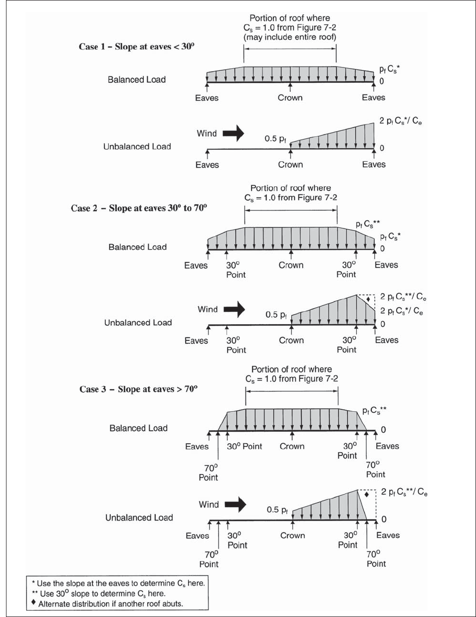
MINIMUM DESIGN LOADS
37
FIGURE 7-3 Balanced and Unbalanced Loads for Curved Roofs.
c07.indd 37 4/14/2010 11:00:55 AM

CHAPTER 7 SNOW LOADS
38
FIGURE 7-4 Partial Loading Diagrams for Continuous Beams.
c07.indd 38 4/14/2010 11:00:55 AM

MINIMUM DESIGN LOADS
39
W
1
S
p decnalaB
s
Unbalanced
W < 20 ft with
roof rafter system
I * p
g
Unbalanced
Other
Sh
3
8
d
Sγh
d
p
s
0.3 p
s
Note: Unbalanced loads need not be considered
for θ > 30.2° (7 on 12) or for θ ≤ 2.38° (1/2 on 12).
FIGURE 7-5 Balanced and Unbalanced Snow Loads for Hip and Gable Roofs.
c07.indd 39 4/14/2010 11:00:55 AM

CHAPTER 7 SNOW LOADS
40
2 p
f
/C
e
∗
p
f
0.5 p
f
Balanced
Load
0
Unbalanced
Load
* May be somewhat less; see Section 7.6.3
0
FIGURE 7-6 Balanced and Unbalanced Snow Loads for a Sawtooth Roof.
FIGURE 7-7 Drifts Formed at Windward and Leeward Steps.
c07.indd 40 4/14/2010 11:00:56 AM

MINIMUM DESIGN LOADS
41
FIGURE 7-8 Confi guration of Snow Drifts on Lower Roofs.
FIGURE 7-9 Graph and Equation for Determining Drift Height, h
d
.
c07.indd 41 4/14/2010 11:00:56 AM

c07.indd 42 4/14/2010 11:00:56 AM

43
Chapter 8
RAIN LOADS
If the secondary drainage systems contain drain
lines, such lines and their point of discharge shall be
separate from the primary drain lines.
8.4 PONDING INSTABILITY
“Ponding” refers to the retention of water due solely
to the defl ection of relatively fl at roofs. Susceptible
bays shall be investigated by structural analysis to
assure that they possess adequate stiffness to preclude
progressive defl ection (i.e., instability) as rain falls on
them or meltwater is created from snow on them.
Bays with a roof slope less than 1/4 in./ft., or on
which water is impounded upon them (in whole or in
part) when the primary drain system is blocked, but
the secondary drain system is functional, shall be
designated as susceptible bays. Roof surfaces with a
slope of at least 1/4 in. per ft (1.19º) towards points of
free drainage need not be considered a susceptible
bay.
The larger of the snow load or the rain load
equal to the design condition for a blocked primary
drain system shall be used in this analysis.
8.5 CONTROLLED DRAINAGE
Roofs equipped with hardware to control the rate of
drainage shall be equipped with a secondary drainage
system at a higher elevation that limits accumulation
of water on the roof above that elevation. Such roofs
shall be designed to sustain the load of all rainwater
that will accumulate on them to the elevation of the
secondary drainage system plus the uniform load
caused by water that rises above the inlet of the
secondary drainage system at its design fl ow (deter-
mined from Section 8.3).
Such roofs shall also be checked for ponding
instability (determined from Section 8.4).
8.1 SYMBOLS
R = rain load on the undefl ected roof, in lb/ft
2
(kN/m
2
). When the phrase “undefl ected roof” is
used, defl ections from loads (including dead
loads) shall not be considered when determining
the amount of rain on the roof.
d
s
= depth of water on the undefl ected roof up to the
inlet of the secondary drainage system when the
primary drainage system is blocked (i.e., the
static head), in in. (mm).
d
h
= additional depth of water on the undefl ected roof
above the inlet of the secondary drainage system
at its design fl ow (i.e., the hydraulic head), in in.
(mm).
8.2 ROOF DRAINAGE
Roof drainage systems shall be designed in accor-
dance with the provisions of the code having jurisdic-
tion. The fl ow capacity of secondary (overfl ow) drains
or scuppers shall not be less than that of the primary
drains or scuppers.
8.3 DESIGN RAIN LOADS
Each portion of a roof shall be designed to sustain the
load of all rainwater that will accumulate on it if the
primary drainage system for that portion is blocked
plus the uniform load caused by water that rises above
the inlet of the secondary drainage system at its
design fl ow.
R = 5.2(d
s
+ d
h
) (8.3-1)
In SI: R = 0.0098(d
s
+ d
h
)
c08.indd 43 4/14/2010 11:00:57 AM

c08.indd 44 4/14/2010 11:00:57 AM

45
Chapter 9
RESERVED FOR FUTURE PROVISIONS
separate sections and to relocate provisions into their
most logical new sections.
The provisions for buildings and nonbuilding
structures are now distinctly separate as are the
provisions for nonstructural components. Less
commonly used provisions, such as those for seismi-
cally isolated structures, have also been located in
their own distinct chapter. We hope that the users of
ASCE 7 will fi nd the reformatted seismic provisions
to be a signifi cant improvement in organization and
presentation over prior editions and will be able to
more quickly locate applicable provisions. Table
C11-1, located in Commentary Chapter C11 of the
2005 edition of ASCE 7 was provided to assist users
in locating provisions between the 2002 and 2005
editions of the standard. Table C11-1 is not included
in this edition of the standard.
In preparing the seismic provisions contained within
this standard, the Seismic Task Committee of ASCE 7
established a Scope and Format Subcommittee to
review the layout and presentation of the seismic
provisions and to make recommendations to improve
the clarity and use of the standard. As a result of the
efforts of this subcommittee, the seismic provisions
of ASCE 7 are presented in Chapters 11 through 23
and Appendices 11A and 11B, as opposed to prior
editions wherein the seismic provisions were pre-
sented in a single section (previously Section 9).
Of foremost concern in the reformat effort was
the organization of the seismic provisions in a logical
sequence for the general structural design community
and the clarifi cation of the various headings to more
accurately refl ect their content. Accomplishing these
two primary goals led to the decision to create 13
c09.indd 45 4/14/2010 11:01:06 AM

c09.indd 46 4/14/2010 11:01:06 AM

47
Chapter 10
ICE LOADS—ATMOSPHERIC ICING
caused or enhanced by an ice accretion on a fl exible
structural member, component, or appurtenance are
not covered in this section.
10.1.3 Exclusions
Electric transmission systems, communications
towers and masts, and other structures for which
national standards exist are excluded from the
requirements of this section. Applicable standards and
guidelines include the NESC, ASCE Manual 74, and
ANSI/EIA/TIA-222.
10.2 DEFINITIONS
The following defi nitions apply only to the provisions
of this chapter.
COMPONENTS AND APPURTENANCES:
Nonstructural elements that may be exposed to
atmospheric icing. Examples are ladders, handrails,
antennas, waveguides, Radio Frequency (RF) trans-
mission lines, pipes, electrical conduits, and cable
trays.
FREEZING RAIN: Rain or drizzle that falls
into a layer of subfreezing air at the earth’s surface
and freezes on contact with the ground or an object to
form glaze ice.
GLAZE: Clear high-density ice.
HOARFROST: An accumulation of ice crystals
formed by direct deposition of water vapor from the
air onto an object.
ICE-SENSITIVE STRUCTURES: Structures
for which the effect of an atmospheric icing load
governs the design of part or all of the structure.
This includes, but is not limited to, lattice structures,
guyed masts, overhead lines, light suspension and
cable-stayed bridges, aerial cable systems (e.g.,
for ski lifts and logging operations), amusement
rides, open catwalks and platforms, fl agpoles, and
signs.
IN-CLOUD ICING: Occurs when supercooled
cloud or fog droplets carried by the wind freeze on
impact with objects. In-cloud icing usually forms
rime, but may also form glaze.
RIME: White or opaque ice with entrapped air.
SNOW: Snow that adheres to objects by some
combination of capillary forces, freezing, and
sintering.
10.1 GENERAL
Atmospheric ice loads due to freezing rain, snow, and
in-cloud icing shall be considered in the design of
ice-sensitive structures. In areas where records or
experience indicate that snow or in-cloud icing
produces larger loads than freezing rain, site-specifi c
studies shall be used. Structural loads due to hoarfrost
are not a design consideration. Roof snow loads are
covered in Chapter 7.
10.1.1 Site-Specifi c Studies
Mountainous terrain and gorges shall be exam-
ined for unusual icing conditions. Site-specifi c studies
shall be used to determine the 50-year mean recur-
rence interval ice thickness, concurrent wind speed,
and concurrent temperature in
1. Alaska.
2. Areas where records or experience indicate that
snow or in-cloud icing produces larger loads than
freezing rain.
3. Special icing regions shown in Figs. 10-2, 10-4,
and 10-5.
4. Mountainous terrain and gorges where examination
indicates unusual icing conditions exist.
Site-specifi c studies shall be subject to review
and approval by the authority having jurisdiction.
In lieu of using the mapped values, it shall be
permitted to determine the ice thickness, the concur-
rent wind speed, and the concurrent temperature for a
structure from local meteorological data based on a
50-year mean recurrence interval provided that
1. The quality of the data for wind and type and
amount of precipitation has been taken into account.
2. A robust ice accretion algorithm has been used to
estimate uniform ice thicknesses and concurrent
wind speeds from these data.
3. Extreme-value statistical analysis procedures
acceptable to the authority having jurisdiction have
been employed in analyzing the ice thickness and
concurrent wind speed data.
4. The length of record and sampling error have been
taken into account.
10.1.2 Dynamic Loads
Dynamic loads, such as those resulting from gallop-
ing, ice shedding, and aeolian vibrations, that are
c10.indd 47 4/14/2010 11:01:02 AM

CHAPTER 10 ICE LOADS—ATMOSPHERIC ICING
48
10.3 SYMBOLS
A
s
= surface area of one side of a fl at plate or the
projected area of complex shapes
A
i
= cross-sectional area of ice
D = diameter of a circular structure or member as
defi ned in Chapter 29, in ft (m)
D
c
= diameter of the cylinder circumscribing an object
f
z
= factor to account for the increase in ice thick-
ness with height
I
i
= importance factor for ice thickness from Table
1.5-2 based on the Risk Category from Table 1.5-1
I
w
= importance factor for concurrent wind pressure
from Table 1.5-2 based on the Risk Category
from Table 1.5-1
K
zt
= topographic factor as defi ned in Chapter 26
q
z
= velocity pressure evaluated at height z above
ground, in lb/ft
2
(N/m
2
) as defi ned in Chapter 29
r = radius of the maximum cross-section of a dome
or radius of a sphere
t = nominal ice thickness due to freezing rain at a
height of 33 ft (10 m) from Figs. 10-2 through
10-6 in inches (mm)
t
d
= design ice thickness in in. (mm) from Eq. 10.4-5
V
c
= concurrent wind speed mph (m/s) from Figs.
10-2 through 10-6
V
i
= volume of ice
z = height above ground in ft (m)
∈ = solidity ratio as defi ned in Chapter 29
10.4 ICE LOADS DUE TO FREEZING RAIN
10.4.1 Ice Weight
The ice load shall be determined using the weight
of glaze ice formed on all exposed surfaces of
structural members, guys, components, appurtenances,
and cable systems. On structural shapes, prismatic
members, and other similar shapes, the cross-sectional
area of ice shall be determined by
A
i
= πt
d
(D
c
+ t
d
) (10.4-1)
D
c
is shown for a variety of cross-sectional shapes in
Fig. 10-1.
On fl at plates and large three-dimensional objects
such as domes and spheres, the volume of ice shall be
determined by
V
i
= πt
d
A
s
(10.4-2)
For a fl at plate A
s
shall be the area of one side of
the plate, for domes and spheres A
s
shall be deter-
mined by
A
s
= πr
2
(10.4-3)
It is acceptable to multiply V
i
by 0.8 for vertical
plates and 0.6 for horizontal plates.
The ice density shall be not less than 56 pcf
(900 kg/m
3
).
10.4.2 Nominal Ice Thickness
Figs. 10-2 through 10-6 show the equivalent
uniform radial thicknesses t of ice due to freezing rain
at a height of 33 ft (10 m) over the contiguous 48
states and Alaska for a 50-year mean recurrence
interval. Also shown are concurrent 3-s gust wind
speeds. Thicknesses for Hawaii, and for ice accretions
due to other sources in all regions, shall be obtained
from local meteorological studies.
10.4.3 Height Factor
The height factor f
z
used to increase the radial
thickness of ice for height above ground z shall be
determined by
f
z
=
z
33
010
⎛
⎝
⎜
⎞
⎠
⎟
.
for 0 ft < z ≤ 900 ft
(10.4-4)
f
z
= 1.4 for z > 900 ft
In SI:
f
z
=
z
10
010
⎛
⎝
⎜
⎞
⎠
⎟
.
for 0 m < z ≤ 275 m
f
z
= 1.4 for z > 275 m
10.4.4 Importance Factors
Importance factors to be applied to the radial
ice thickness and wind pressure shall be determined
from Table 1.5-2 based on the Risk Category from
Table 1.5-1. The importance factor I
i
shall be
applied to the ice thickness, not the ice weight,
because the ice weight is not a linear function of
thickness.
10.4.5 Topographic Factor
Both the ice thickness and concurrent wind speed
for structures on hills, ridges, and escarpments are
higher than those on level terrain because of wind
speed-up effects. The topographic factor for the
concurrent wind pressure is K
zt
and the topographic
factor for ice thickness is (K
zt
)
0.35
, where K
zt
is
obtained from Eq. 26.8-1.
10.4.6 Design Ice Thickness for Freezing Rain
The design ice thickness t
d
shall be calculated
from Eq. 10.4-5.
t
d
= 2.0tI
i
f
z
(K
zt
)
0.35
(10.4-5)
c10.indd 48 4/14/2010 11:01:02 AM

MINIMUM DESIGN LOADS
49
10.5 WIND ON ICE-COVERED STRUCTURES
Ice accreted on structural members, components, and
appurtenances increases the projected area of the
structure exposed to wind. The projected area shall be
increased by adding t
d
to all free edges of the projected
area. Wind loads on this increased projected area
shall be used in the design of ice-sensitive structures.
Figs. 10-2 to 10-6 include 3-s gust wind speeds at
33 ft (10 m) above grade that are concurrent with the
ice loads due to freezing rain. Wind loads shall be
calculated in accordance with Chapters 26 through 31
as modifi ed by Sections 10.5.1 through 10.5.5.
10.5.1 Wind on Ice-Covered Chimneys, Tanks, and
Similar Structures
Force coeffi cients C
f
for structures with square,
hexagonal, and octagonal cross-sections shall be as
given in Fig. 29.5-1. Force coeffi cients C
f
for struc-
tures with round cross-sections shall be as given in
Fig. 29.5-1 for round cross-sections with D√q
z
≤ 2.5
for all ice thicknesses, wind speeds, and structure
diameters.
10.5.2 Wind on Ice-Covered Solid Freestanding
Walls and Solid Signs
Force coeffi cients C
f
shall be as given in Fig.
29.4 based on the dimensions of the wall or sign
including ice.
10.5.3 Wind on Ice-Covered Open Signs and
Lattice Frameworks
The solidity ratio ∈ shall be based on the
projected area including ice. The force coeffi cient C
f
for the projected area of fl at members shall be as
given in Fig. 29.5-2. The force coeffi cient C
f
for
rounded members and for the additional projected
area due to ice on both fl at and rounded members
shall be as given in Fig. 29.5-2 for rounded members
with D√q
z
≤ 2.5 for all ice thicknesses, wind speeds,
and member diameters.
10.5.4 Wind on Ice-Covered Trussed Towers
The solidity ratio ∈ shall be based on the projected
area including ice. The force coeffi cients C
f
shall be as
given in Fig. 29.5-3. It is acceptable to reduce the force
coeffi cients C
f
for the additional projected area due to
ice on both round and fl at members by the factor for
rounded members in Note 3 of Fig. 29.5-3.
10.5.5 Wind on Ice-Covered Guys and Cables
The force coeffi cient C
f
(as defi ned in Chapter
29) for ice-covered guys and cables shall be 1.2.
10.6 Design Temperatures for Freezing Rain
The design temperatures for ice and wind-on-ice due
to freezing rain shall be either the temperature for
the site shown in Figs. 10-7 and 10-8 or 32°F (0°C),
whichever gives the maximum load effect. The
temperature for Hawaii shall be 32°F (0°C). For
temperature sensitive structures, the load shall include
the effect of temperature change from everyday
conditions to the design temperature for ice and
wind-on-ice. These temperatures are to be used with
ice thicknesses for all mean recurrence intervals. The
design temperatures are considered to be concurrent
with the design ice load and the concurrent wind load.
10.7 PARTIAL LOADING
The effects of a partial ice load shall be considered
when this condition is critical for the type of structure
under consideration. It is permitted to consider this to
be a static load.
10.8 DESIGN PROCEDURE
1. The nominal ice thickness, t, the concurrent wind
speed, V
c
, and the concurrent temperature for the
site shall be determined from Figs. 10-2 to 10-8
or a site-specifi c study.
2. The topographic factor for the site, K
zt
,
shall be determined in accordance with
Section 10.4.5.
3. The importance factor for ice thickness, I
i
,
shall be determined in accordance with
Section 10.4.4.
4. The height factor, f
z
, shall be determined in
accordance with Section 10.4.3 for each design
segment of the structure.
5. The design ice thickness, t
d
, shall be determined
in accordance with Section 10.4.6, Eq. 10.4-5.
6. The weight of ice shall be calculated for the
design ice thickness, t
d
, in accordance with
Section 10.4.1.
7. The velocity pressure q
z
for wind speed V
c
shall
be determined in accordance with Section 29.3
using the importance factor for concurrent wind
pressure I
w
determined in accordance with Section
10.4.4.
8. The wind force coeffi cients C
f
shall be deter-
mined in accordance with Section 10.5.
9. The gust effect factor shall be determined in
accordance with Section 26.9.
c10.indd 49 4/14/2010 11:01:02 AM

CHAPTER 10 ICE LOADS—ATMOSPHERIC ICING
50
10. The design wind force shall be determined in
accordance with Chapter 29.
11. The iced structure shall be analyzed for the load
combinations in either Section 2.3 or 2.4.
10.9 CONSENSUS STANDARDS AND OTHER
REFERENCED DOCUMENTS
This section lists the consensus standards and other
documents that are adopted by reference within this
chapter:
ASCE
American Society of Civil Engineers
1801 Alexander Bell Drive
Reston, VA 20191
ASCE Manual 74
Section 10.1.3
Guidelines for Electrical Transmission Line Structural
Loading, 1991
ANSI
American National Standards Institute
25 West 43rd Street, 4th Floor
New York, NY 10036
ANSI/EIA/TIA-222
Section 10.1.3
Structural Standards for Steel Antenna Towers and
Antenna Supporting Structures, 1996
IEEE
445 Hoes Lane
Piscataway, NJ 08854-1331
NESC
Section 10.1.3
National Electrical Safety Code, 2001
c10.indd 50 4/14/2010 11:01:02 AM
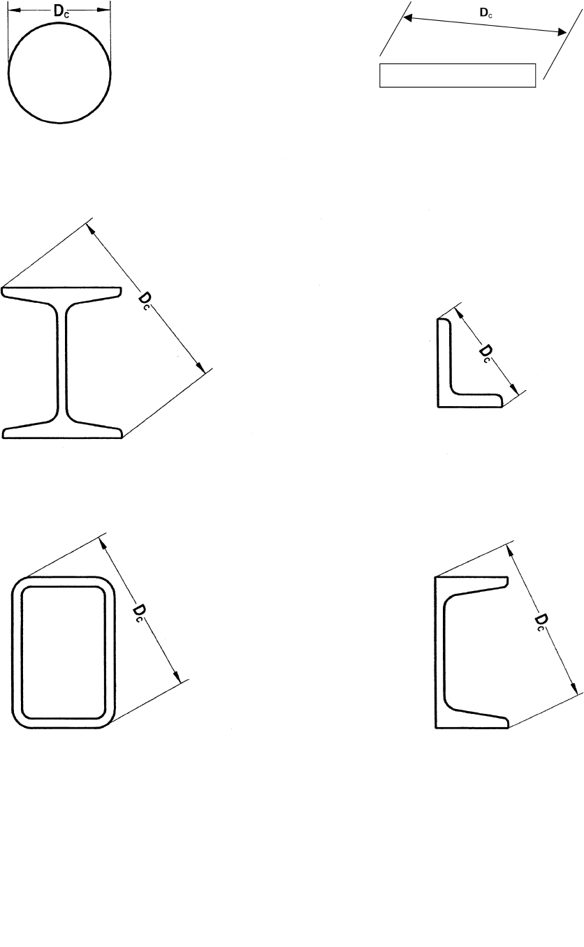
MINIMUM DESIGN LOADS
51
FIGURE 10-1 Characteristic Dimension D
c
for Calculating the Ice Area for a Variety of Cross-Sectional
Shapes.
c10.indd 51 4/14/2010 11:01:02 AM
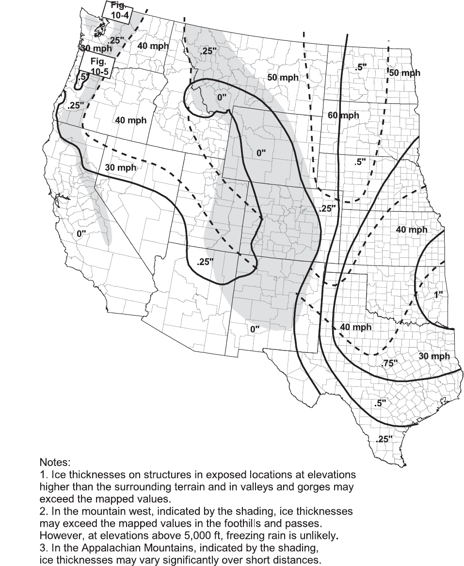
CHAPTER 10 ICE LOADS—ATMOSPHERIC ICING
52
FIGURE 10-2 Equivalent Radial Ice Thicknesses Due to Freezing Rain with Concurrent 3-Second Gust
Speeds, for a 50-Year Mean Recurrence Interval.
c10.indd 52 4/14/2010 11:01:03 AM

MINIMUM DESIGN LOADS
53
FIGURE 10-2 (Continued)
c10.indd 53 4/14/2010 11:01:03 AM
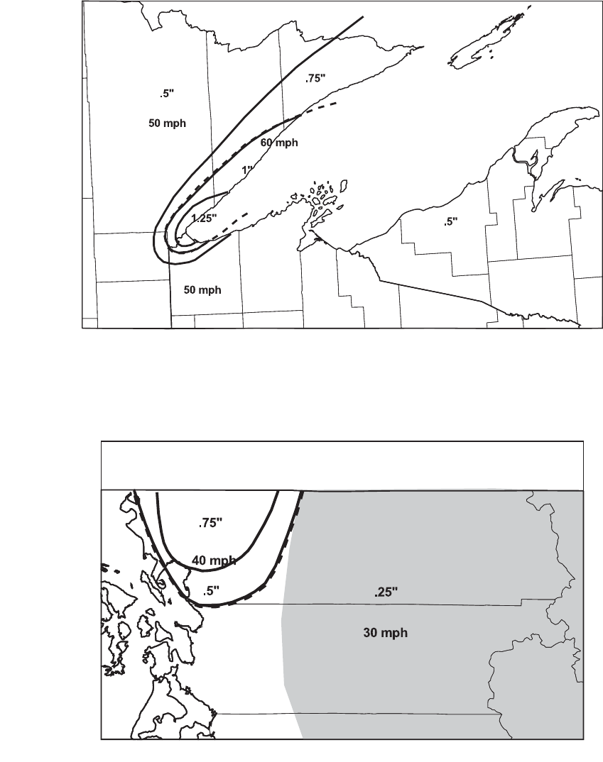
CHAPTER 10 ICE LOADS—ATMOSPHERIC ICING
54
FIGURE 10-3 Lake Superior Detail.
FIGURE 10-4 Fraser Valley Detail.
c10.indd 54 4/14/2010 11:01:04 AM

FIGURE 10-5 Columbia River Gorge Detail.
FIGURE 10-6 50-Yr Mean Recurrence Interval Uniform Ice Thicknesses Due to Freezing Rain with
Concurrent 3-Second Gust Speeds: Alaska.
c10.indd 55 4/14/2010 11:01:04 AM

FIGURE 10-7 Temperatures Concurrent with Ice Thicknesses Due to Freezing Rain: Contiguous 48 States.
FIGURE 10-8 Temperatures Concurrent with Ice Thicknesses Due to Freezing Rain: Alaska.
c10.indd 56 4/14/2010 11:01:04 AM

57
Chapter 11
SEISMIC DESIGN CRITERIA
vehicular bridges, electrical transmission towers,
hydraulic structures, buried utility lines and their
appurtenances, and nuclear reactors.
5. Piers and wharves that are not accessible to the
general public.
11.1.3 Applicability
Structures and their nonstructural components
shall be designed and constructed in accordance with
the requirement of the following sections based on the
type of structure or component:
a. Buildings: Chapter 12
b. Nonbuilding Structures: Chapter 15
c. Nonstructural Components: Chapter 13
d. Seismically Isolated Structures: Chapter 17
e. Structures with Damping Systems: Chapter 18
Buildings whose purpose is to enclose equipment or
machinery and whose occupants are engaged in
maintenance or monitoring of that equipment,
machinery or their associated processes shall be
permitted to be classifi ed as nonbuilding structures
designed and detailed in accordance with Section 15.5
of this standard.
11.1.4 Alternate Materials and Methods
of Construction
Alternate materials and methods of construction
to those prescribed in the seismic requirements of this
standard shall not be used unless approved by the
authority having jurisdiction. Substantiating evidence
shall be submitted demonstrating that the proposed
alternate, for the purpose intended, will be at least
equal in strength, durability, and seismic resistance.
11.2 DEFINITIONS
The following defi nitions apply only to the seismic
requirements of this standard.
ACTIVE FAULT: A fault determined to be
active by the authority having jurisdiction from
properly substantiated data (e.g., most recent mapping
of active faults by the United States Geological
Survey).
ADDITION: An increase in building area,
aggregate fl oor area, height, or number of stories of a
structure.
11.1 GENERAL
11.1.1 Purpose
Chapter 11 presents criteria for the design and
construction of buildings and other structures subject
to earthquake ground motions. The specifi ed earth-
quake loads are based upon post-elastic energy
dissipation in the structure, and because of this fact,
the requirements for design, detailing, and construc-
tion shall be satisfi ed even for structures and members
for which load combinations that do not contain
earthquake loads indicate larger demands than
combinations that include earthquake loads. Minimum
requirements for quality assurance for seismic
force-resisting systems are set forth in Appendix 11A.
11.1.2 Scope
Every structure, and portion thereof, including
nonstructural components, shall be designed and
constructed to resist the effects of earthquake motions
as prescribed by the seismic requirements of this
standard. Certain nonbuilding structures, as described
in Chapter 15, are also within the scope and shall be
designed and constructed in accordance with the
requirements of Chapter 15. Requirements concerning
alterations, additions, and change of use are set forth
in Appendix 11B. Existing structures and alterations to
existing structures need only comply with the seismic
requirements of this standard where required by
Appendix 11B. The following structures are exempt
from the seismic requirements of this standard:
1. Detached one- and two-family dwellings that are
located where the mapped, short period, spectral
response acceleration parameter, S
S
, is less than 0.4
or where the Seismic Design Category determined
in accordance with Section 11.6 is A, B, or C.
2. Detached one- and two-family wood-frame
dwellings not included in Exception 1 with not
more than two stories above grade plane, satisfying
the limitations of and constructed in accordance
with the IRC.
3. Agricultural storage structures that are intended
only for incidental human occupancy.
4. Structures that require special consideration of their
response characteristics and environment that are
not addressed in Chapter 15 and for which other
regulations provide seismic criteria, such as
c11.indd 57 4/14/2010 11:01:13 AM

CHAPTER 11 SEISMIC DESIGN CRITERIA
58
ALTERATION: Any construction or renovation
to an existing structure other than an addition.
APPENDAGE: An architectural component such
as a canopy, marquee, ornamental balcony, or
statuary.
APPROVAL: The written acceptance by the
authority having jurisdiction of documentation
that establishes the qualifi cation of a material,
system, component, procedure, or person to fulfi ll
the requirements of this standard for the intended
use.
ATTACHMENTS: Means by which nonstruc-
tural components or supports of nonstructural compo-
nents are secured or connected to the seismic
force-resisting system of the structure. Such attach-
ments include anchor bolts, welded connections, and
mechanical fasteners.
BASE: The level at which the horizontal seismic
ground motions are considered to be imparted to the
structure.
BASE SHEAR: Total design lateral force or
shear at the base.
BOUNDARY ELEMENTS: Diaphragm and
shear wall boundary members to which the diaphragm
transfers forces. Boundary members include chords
and drag struts at diaphragm and shear wall perim-
eters, interior openings, discontinuities, and reentrant
corners.
BOUNDARY MEMBERS: Portions along wall
and diaphragm edges strengthened by longitudinal and
transverse reinforcement. Boundary members include
chords and drag struts at diaphragm and shear wall
perimeters, interior openings, discontinuities, and
reentrant corners.
BUILDING: Any structure whose intended use
includes shelter of human occupants.
CANTILEVERED COLUMN SYSTEM: A
seismic force-resisting system in which lateral forces
are resisted entirely by columns acting as cantilevers
from the base.
CHARACTERISTIC EARTHQUAKE: An
earthquake assessed for an active fault having a
magnitude equal to the best estimate of the maximum
magnitude capable of occurring on the fault, but not
less than the largest magnitude that has occurred
historically on the fault.
COMPONENT: A part of an architectural,
electrical, or mechanical system.
Component, Nonstructural: A part of an
architectural, mechanical, or electrical system
within or without a building or nonbuilding
structure.
Component, Flexible: Nonstructural component
having a fundamental period greater than
0.06 s.
Component, Rigid: Nonstructural component
having a fundamental period less than or equal
to 0.06 s.
CONCRETE, PLAIN: Concrete that is either
unreinforced or contains less reinforcement than the
minimum amount specifi ed in ACI 318 for reinforced
concrete.
CONCRETE, REINFORCED: Concrete
reinforced with no less reinforcement than the
minimum amount required by ACI 318 prestressed
or nonprestressed, and designed on the assumption
that the two materials act together in resisting
forces.
CONSTRUCTION DOCUMENTS: The
written, graphic, electronic, and pictorial documents
describing the design, locations, and physical charac-
teristics of the project required to verify compliance
with this standard.
COUPLING BEAM: A beam that is used to
connect adjacent concrete wall elements to make them
act together as a unit to resist lateral loads.
DEFORMABILITY: The ratio of the ultimate
deformation to the limit deformation.
High-Deformability Element: An element
whose deformability is not less than 3.5 where
subjected to four fully reversed cycles at the
limit deformation.
Limited-Deformability Element: An element
that is neither a low-deformability nor a
high-deformability element.
Low-Deformability Element: An element whose
deformability is 1.5 or less.
DEFORMATION:
Limit Deformation: Two times the initial
deformation that occurs at a load equal to 40
percent of the maximum strength.
Ultimate Deformation: The deformation at
which failure occurs and that shall be deemed
to occur if the sustainable load reduces to 80
percent or less of the maximum strength.
DESIGNATED SEISMIC SYSTEMS: Those
nonstructural components that require design in
accordance with Chapter 13 and for which the
component importance factor, I
p
, is greater than 1.0.
DESIGN EARTHQUAKE: The earthquake
effects that are two-thirds of the corresponding
Maximum Considered Earthquake (MCE
R
) effects.
c11.indd 58 4/14/2010 11:01:14 AM

MINIMUM DESIGN LOADS
59
DESIGN EARTHQUAKE GROUND
MOTION: The earthquake ground motions that are
two-thirds of the corresponding MCE
R
ground
motions.
DIAPHRAGM: Roof, fl oor, or other membrane
or bracing system acting to transfer the lateral forces
to the vertical resisting elements.
DIAPHRAGM BOUNDARY: A location where
shear is transferred into or out of the diaphragm
element. Transfer is either to a boundary element or
to another force-resisting element.
DIAPHRAGM CHORD: A diaphragm bound-
ary element perpendicular to the applied load that is
assumed to take axial stresses due to the diaphragm
moment.
DRAG STRUT (COLLECTOR, TIE, DIA-
PHRAGM STRUT): A diaphragm or shear wall
boundary element parallel to the applied load that
collects and transfers diaphragm shear forces to the
vertical force-resisting elements or distributes forces
within the diaphragm or shear wall.
ENCLOSURE: An interior space surrounded by
walls.
EQUIPMENT SUPPORT: Those structural
members or assemblies of members or manufactured
elements, including braces, frames, legs, lugs,
snuggers, hangers, or saddles that transmit gravity
loads and operating loads between the equipment and
the structure.
FLEXIBLE CONNECTIONS: Those connec-
tions between equipment components that permit
rotational and/or translational movement without
degradation of performance. Examples include
universal joints, bellows expansion joints, and fl exible
metal hose.
FRAME:
Braced Frame: An essentially vertical truss, or
its equivalent, of the concentric or eccentric
type that is provided in a building frame
system or dual system to resist seismic
forces.
Concentrically Braced Frame (CBF): A
braced frame in which the members are
subjected primarily to axial forces. CBFs are
categorized as ordinary concentrically braced
frames (OCBFs) or special concentrically
braced frames (SCBFs).
Eccentrically Braced Frame (EBF): A
diagonally braced frame in which at least
one end of each brace frames into a beam a
short distance from a beam-column or from
another diagonal brace.
Moment Frame: A frame in which members and
joints resist lateral forces by fl exure as well as
along the axis of the members. Moment frames
are categorized as intermediate moment frames
(IMF), ordinary moment frames (OMF), and
special moment frames (SMF).
Structural System:
Building Frame System: A structural system
with an essentially complete space frame
providing support for vertical loads. Seismic
force resistance is provided by shear walls or
braced frames.
Dual System: A structural system with an
essentially complete space frame providing
support for vertical loads. Seismic force
resistance is provided by moment-resisting
frames and shear walls or braced frames as
prescribed in Section 12.2.5.1.
Shear Wall-Frame Interactive System: A
structural system that uses combinations of
ordinary reinforced concrete shear walls and
ordinary reinforced concrete moment frames
designed to resist lateral forces in proportion to
their rigidities considering interaction between
shear walls and frames on all levels.
Space Frame System: A 3-D structural system
composed of interconnected members, other
than bearing walls, that is capable of support-
ing vertical loads and, where designed for such
an application, is capable of providing resis-
tance to seismic forces.
FRICTION CLIP: A device that relies on
friction to resist applied loads in one or more direc-
tions to anchor a nonstructural component. Friction is
provided mechanically and is not due to gravity loads.
GLAZED CURTAIN WALL: A nonbearing
wall that extends beyond the edges of building fl oor
slabs, and includes a glazing material installed in the
curtain wall framing.
GLAZED STOREFRONT: A nonbearing wall
that is installed between fl oor slabs, typically includ-
ing entrances, and includes a glazing material installed
in the storefront framing.
GRADE PLANE: A horizontal reference plane
representing the average of fi nished ground level
adjoining the structure at all exterior walls. Where the
fi nished ground level slopes away from the exterior
walls, the grade plane is established by the lowest
points within the area between the structure and the
property line or, where the property line is more than 6
ft (1,829 mm) from the structure, between the structure
and points 6 ft (1,829 mm) from the structure.
c11.indd 59 4/14/2010 11:01:14 AM

CHAPTER 11 SEISMIC DESIGN CRITERIA
60
INSPECTION, SPECIAL: The observation of
the work by a special inspector to determine compli-
ance with the approved construction documents and
these standards in accordance with the quality
assurance plan.
Continuous Special Inspection: The full-time
observation of the work by a special inspector
who is present in the area where work is being
performed.
Periodic Special Inspection: The part-time or
intermittent observation of the work by a
special inspector who is present in the area
where work has been or is being performed.
INSPECTOR, SPECIAL (who shall be identi-
fi ed as the owner’s inspector): A person approved
by the authority having jurisdiction to perform special
inspection.
INVERTED PENDULUM-TYPE STRUC-
TURES: Structures in which more than 50 percent of
the structure’s mass is concentrated at the top of a
slender, cantilevered structure and in which stability
of the mass at the top of the structure relies on
rotational restraint to the top of the cantilevered
element.
JOINT: The geometric volume common to
intersecting members.
LIGHT-FRAME CONSTRUCTION: A method
of construction where the structural assemblies (e.g.,
walls, fl oors, ceilings, and roofs) are primarily formed
by a system of repetitive wood or cold-formed steel
framing members or subassemblies of these members
(e.g., trusses).
LONGITUDINAL REINFORCEMENT
RATIO: Area of longitudinal reinforcement divided
by the cross-sectional area of the concrete.
MAXIMUM CONSIDERED EARTHQUAKE
(MCE) GROUND MOTION: The most severe
earthquake effects considered by this standard more
specifi cally defi ned in the following two terms.
MAXIMUM CONSIDERED EARTHQUAKE
GEOMETRIC MEAN (MCE
G
) PEAK GROUND
ACCELERATION: The most severe earthquake
effects considered by this standard determined for
geometric mean peak ground acceleration and
without adjustment for targeted risk. The MCE
G
peak ground acceleration adjusted for site effects
(PGA
M
) is used in this standard for evaluation of
liquefaction, lateral spreading, seismic settlements,
and other soil related issues. In this standard, general
procedures for determining PGA
M
are provided in
Section 11.8.3; site-specifi c procedures are provided
in Section 21.5.
RISK-TARGETED MAXIMUM CONSID-
ERED EARTHQUAKE (MCE
R
) GROUND
MOTION RESPONSE ACCELERATION: The
most severe earthquake effects considered by this
standard determined for the orientation that results in
the largest maximum response to horizontal ground
motions and with adjustment for targeted risk. In
this standard, general procedures for determining
the MCE
R
Ground Motion values are provided in
Section 11.4.3; site-specifi c procedures are provided
in Sections 21.1 and 21.2.
MECHANICALLY ANCHORED TANKS OR
VESSELS: Tanks or vessels provided with mechani-
cal anchors to resist overturning moments.
NONBUILDING STRUCTURE: A structure,
other than a building, constructed of a type included
in Chapter 15 and within the limits of Section 15.1.1.
NONBUILDING STRUCTURE SIMILAR TO
A BUILDING: A nonbuilding structure that is
designed and constructed in a manner similar to
buildings, will respond to strong ground motion in a
fashion similar to buildings, and has a basic lateral
and vertical seismic force-resisting system conforming
to one of the types indicated in Tables 12.2-1 or
15.4-1.
ORTHOGONAL: To be in two horizontal
directions, at 90° to each other.
OWNER: Any person, agent, fi rm, or corporation
having a legal or equitable interest in the property.
PARTITION: A nonstructural interior wall that
spans horizontally or vertically from support to
support. The supports may be the basic building
frame, subsidiary structural members, or other
portions of the partition system.
P-DELTA EFFECT: The secondary effect on
shears and moments of structural members due to the
action of the vertical loads induced by horizontal
displacement of the structure resulting from various
loading conditions.
PILE: Deep foundation element, which includes
piers, caissons, and piles.
PILE CAP: Foundation elements to which piles
are connected including grade beams and mats.
REGISTERED DESIGN PROFESSIONAL:
An architect or engineer, registered or licensed to
practice professional architecture or engineering, as
defi ned by the statutory requirements of the profes-
sional registrations laws of the state in which the
project is to be constructed.
SEISMIC DESIGN CATEGORY: A classifi ca-
tion assigned to a structure based on its Risk Category
and the severity of the design earthquake ground
motion at the site as defi ned in Section 11.4.
c11.indd 60 4/14/2010 11:01:14 AM

MINIMUM DESIGN LOADS
61
SEISMIC FORCE-RESISTING SYSTEM:
That part of the structural system that has been
considered in the design to provide the required
resistance to the seismic forces prescribed herein.
SEISMIC FORCES: The assumed forces
prescribed herein, related to the response of the
structure to earthquake motions, to be used in the
design of the structure and its components.
SELF-ANCHORED TANKS OR VESSELS:
Tanks or vessels that are stable under design overturn-
ing moment without the need for mechanical anchors
to resist uplift.
SHEAR PANEL: A fl oor, roof, or wall element
sheathed to act as a shear wall or diaphragm.
SITE CLASS: A classifi cation assigned to a site
based on the types of soils present and their engineer-
ing properties as defi ned in Chapter 20.
STORAGE RACKS: Include industrial pallet
racks, moveable shelf racks, and stacker racks made
of cold-formed or hot-rolled structural members. Does
not include other types of racks such as drive-in and
drive-through racks, cantilever racks, portable racks,
or racks made of materials other than steel.
STORY: The portion of a structure between the
tops of two successive fl oor surfaces and, for the
topmost story, from the top of the fl oor surface to the
top of the roof surface.
STORY ABOVE GRADE PLANE: A story in
which the fl oor or roof surface at the top of the story
is more than 6 ft (1,828 mm) above grade plane or is
more than 12 ft (3,658 mm) above the fi nished ground
level at any point on the perimeter of the structure.
STORY DRIFT: The horizontal defl ection at the
top of the story relative to the bottom of the story as
determined in Section 12.8.6.
STORY DRIFT RATIO: The story drift, as
determined in Section 12.8.6, divided by the story
height, h
sx
.
STORY SHEAR: The summation of design
lateral seismic forces at levels above the story under
consideration.
STRENGTH:
Design Strength: Nominal strength multiplied by
a strength reduction factor, ϕ.
Nominal Strength: Strength of a member or
cross-section calculated in accordance with the
requirements and assumptions of the strength
design methods of this standard (or the
reference documents) before application of any
strength-reduction factors.
Required Strength: Strength of a member,
cross-section, or connection required to resist
factored loads or related internal moments and
forces in such combinations as stipulated by
this standard.
STRUCTURAL HEIGHT: The vertical distance
from the base to the highest level of the seismic
force-resisting system of the structure. For pitched or
sloped roofs, the structural height is from the base to
the average height of the roof.
STRUCTURAL OBSERVATIONS: The
visual observations to determine that the seismic
force-resisting system is constructed in general
conformance with the construction documents.
STRUCTURE: That which is built or con-
structed and limited to buildings and nonbuilding
structures as defi ned herein.
SUBDIAPHRAGM: A portion of a diaphragm
used to transfer wall anchorage forces to diaphragm
cross ties.
SUPPORTS: Those members, assemblies of
members, or manufactured elements, including braces,
frames, legs, lugs, snubbers, hangers, saddles, or
struts, and associated fasteners that transmit loads
between nonstructural components and their attach-
ments to the structure.
TESTING AGENCY: A company or
corporation that provides testing and/or inspection
services.
VENEERS: Facings or ornamentation of brick,
concrete, stone, tile, or similar materials attached to a
backing.
WALL: A component that has a slope of 60° or
greater with the horizontal plane used to enclose or
divide space.
Bearing Wall: Any wall meeting either of the
following classifi cations:
1. Any metal or wood stud wall that supports
more than 100 lb/linear ft (1,459 N/m) of
vertical load in addition to its own weight.
2. Any concrete or masonry wall that supports
more than 200 lb/linear ft (2,919 N/m) of
vertical load in addition to its own weight.
Light Frame Wall: A wall with wood or steel
studs.
Light Frame Wood Shear Wall: A wall
constructed with wood studs and sheathed with
material rated for shear resistance.
Nonbearing Wall: Any wall that is not a bearing
wall.
Nonstructural Wall: All walls other than bearing
walls or shear walls.
Shear Wall (Vertical Diaphragm): A wall,
bearing or nonbearing, designed to resist lateral
c11.indd 61 4/14/2010 11:01:14 AM

CHAPTER 11 SEISMIC DESIGN CRITERIA
62
forces acting in the plane of the wall (some-
times referred to as a “vertical diaphragm”).
Structural Wall: Walls that meet the defi nition
for bearing walls or shear walls.
WALL SYSTEM, BEARING: A structural
system with bearing walls providing support for all or
major portions of the vertical loads. Shear walls or
braced frames provide seismic force resistance.
WOOD STRUCTURAL PANEL: A wood-
based panel product that meets the requirements of
DOC PS1 or DOC PS2 and is bonded with a water-
proof adhesive. Included under this designation are
plywood, oriented strand board, and composite
panels.
11.3 SYMBOLS
The unit dimensions used with the items covered by
the symbols shall be consistent throughout except
where specifi cally noted. Symbols presented in this
section apply only to the seismic requirements in this
standard as indicated.
A
ch
= cross-sectional area (in.
2
or mm
2
) of a
structural member measured out-to-out of
transverse reinforcement
A
0
= area of the load-carrying foundation
(ft
2
or m
2
)
A
sh
= total cross-sectional area of hoop rein-
forcement (in.
2
or mm
2
), including
supplementary cross-ties, having a
spacing of s
h
and crossing a section with
a core dimension of h
c
A
vd
= required area of leg (in.
2
or mm
2
) of
diagonal reinforcement
A
x
= torsional amplifi cation factor (Section
12.8.4.3)
a
i
= the acceleration at level i obtained from a
modal analysis (Section 13.3.1)
a
p
= the amplifi cation factor related to the
response of a system or component as
affected by the type of seismic attach-
ment, determined in Section 13.3.1
b
p
= the width of the rectangular glass panel
C
d
= defl ection amplifi cation factor as given in
Tables 12.2-1, 15.4-1, or 15.4-2
C
R
= site-specifi c risk coeffi cient at any period;
see Section 21.2.1.1
C
RS
= mapped value of the risk coeffi cient at
short periods as given by Fig. 22-17
C
R1
= mapped value of the risk coeffi cient at a
period of 1 s as given by Fig. 22-18
C
s
= seismic response coeffi cient determined in
Section 12.8.1.1 and 19.3.1 (dimensionless)
C
T
= building period coeffi cient in Section
12.8.2.1
C
vx
= vertical distribution factor as determined
in Section 12.8.3
c = distance from the neutral axis of a
fl exural member to the fi ber of maximum
compressive strain (in. or mm)
D = the effect of dead load
D
clear
= relative horizontal (drift) displacement,
measured over the height of the glass
panel under consideration, which causes
initial glass-to-frame contact. For rectan-
gular glass panels within a rectangular
wall frame, D
clear
is set forth in Section
13.5.9.1
D
pI
= seismic relative displacement; see Section
13.3.2
D
s
= the total depth of stratum in Eq. 19.2-12
(ft or m)
d
C
= The total thickness of cohesive soil layers
in the top 100 ft (30 m); see Section
20.4.3 (ft or m)
d
i
= The thickness of any soil or rock layer i
(between 0 and 100 ft [30 m]); see
Section 20.4.1 (ft or m)
d
S
= The total thickness of cohesionless soil
layers in the top 100 ft (30 m); see
Section 20.4.2 (ft or m)
E = effect of horizontal and vertical earth-
quake-induced forces (Section 12.4)
F
a
= short-period site coeffi cient (at 0.2
s-period); see Section 11.4.3
F
i
, F
n
, F
x
= portion of the seismic base shear, V,
induced at Level i, n, or x, respectively,
as determined in Section 12.8.3
F
p
= the seismic force acting on a component
of a structure as determined in Sections
12.11.1 and 13.3.1
F
PGA
= site coeffi cient for PGA; see Section 11.8.3
F
v
= long-period site coeffi cient (at 1.0
s-period); see Section 11.4.3
f
c
′ = specifi ed compressive strength of concrete
used in design
f
s
′ = ultimate tensile strength (psi or MPa) of the
bolt, stud, or insert leg wires. For ASTM
A307 bolts or A108 studs, it is permitted to
be assumed to be 60,000 psi (415 MPa)
f
y
= specifi ed yield strength of reinforcement
(psi or MPa)
f
yh
= specifi ed yield strength of the special
lateral reinforcement (psi or kPa)
c11.indd 62 4/14/2010 11:01:14 AM

MINIMUM DESIGN LOADS
63
G = γυ
s
2
/g = the average shear modulus for the
soils beneath the foundation at
large strain levels (psf or Pa)
G
0
= γυ
s0
2
/g = the average shear modulus for
the soils beneath the foundation
at small strain levels (psf or Pa)
g = acceleration due to gravity
H = thickness of soil
h = height of a shear wall measured as the
maximum clear height from top of
foundation to bottom of diaphragm
framing above, or the maximum clear
height from top of diaphragm to bottom
of diaphragm framing above
h = average roof height of structure with
respect to the base; see Chapter 13
h
_
= effective height of the building as
determined in Section 19.2.1.1 or 19.3.1
(ft or m)
h
c
= core dimension of a component measured
to the outside of the special lateral
reinforcement (in. or mm)
h
i
, h
x
= the height above the base to Level i or x,
respectively
h
n
= structural height as defi ned in Section 11.2
h
p
= the height of the rectangular glass panel
h
sx
= the story height below Level
x = (h
x
– h
x–1
)
I
e
= the importance factor as prescribed in
Section 11.5.1
I
0
= the static moment of inertia of the
load-carrying foundation; see Section
19.2.1.1 (in.
4
or mm
4
)
I
p
= the component importance factor as
prescribed in Section 13.3.1
i = the building level referred to by the
subscript i; i = 1 designates the fi rst level
above the base
K
p
= the stiffness of the component or attach-
ment, Section 13.6.2
K
y
= the lateral stiffness of the foundation as
defi ned in Section 19.2.1.1 (lb/in. or N/m)
K
θ
= the rocking stiffness of the foundation as
defi ned in Section 19.2.1.1 (ft-lb/degree
or N-m/rad)
KL/r = the lateral slenderness ratio of a compres-
sion member measured in terms of its
effective length, KL, and the least radius
of gyration of the member cross section, r
k = distribution exponent given in Section
12.8.3
k
_
= stiffness of the building as determined in
Section 19.2.1.1 (lb/ft or N/m)
k
a
= coeffi cient defi ned in Sections 12.11.2
and 12.14.7.5
L = overall length of the building (ft or m) at
the base in the direction being analyzed
L
0
= overall length of the side of the founda-
tion in the direction being analyzed,
Section 19.2.1.2 (ft or m)
M
0
, M
01
= the overturning moment at the founda-
tion–soil interface as determined in
Sections 19.2.3 and 19.3.2 (ft-lb or N-m)
M
t
= torsional moment resulting from eccen-
tricity between the locations of center of
mass and the center of rigidity (Section
12.8.4.1)
M
ta
= accidental torsional moment as deter-
mined in Section 12.8.4.2
m = a subscript denoting the mode of vibra-
tion under consideration; that is, m = 1
for the fundamental mode
N = standard penetration resistance, ASTM
D-1586
N = number of stories above the base (Section
12.8.2.1)
N
_
= average fi eld standard penetration
resistance for the top 100 ft (30 m); see
Sections 20.3.3 and 20.4.2
N
_
ch
= average standard penetration resistance
for cohesionless soil layers for the top
100 ft (30 m); see Sections 20.3.3 and
20.4.2
N
i
= standard penetration resistance of any
soil or rock layer i (between 0 and 100 ft
[30 m]); see Section 20.4.2
n = designation for the level that is uppermost
in the main portion of the building
PGA = mapped MCE
G
peak ground acceleration
shown in Figs. 22-6 through 22-10
PGA
M
= MCE
G
peak ground acceleration adjusted
for Site Class effects; see Section 11.8.3
P
x
= total unfactored vertical design load at and
above level x, for use in Section 12.8.7
PI = plasticity index, ASTM D4318
Q
E
= effect of horizontal seismic (earthquake-
induced) forces
R = response modifi cation coeffi cient as given
in Tables 12.2-1, 12.14-1, 15.4-1, or
15.4-2
R
p
= component response modifi cation factor
as defi ned in Section 13.3.1
r = a characteristic length of the foundation
as defi ned in Section 19.2.1.2
r
a
= characteristic foundation length as defi ned
by Eq. 19.2-7 (ft or m)
c11.indd 63 4/14/2010 11:01:14 AM

CHAPTER 11 SEISMIC DESIGN CRITERIA
64
r
m
= characteristic foundation length as defi ned
by Eq. 19.2-8 (ft or m)
S
S
= mapped MCE
R
, 5 percent damped,
spectral response acceleration parameter
at short periods as defi ned in Section
11.4.1
S
1
= mapped MCE
R
, 5 percent damped,
spectral response acceleration parameter
at a period of 1 s as defi ned in Section
11.4.1
S
aM
= the site-specifi c MCE
R
spectral response
acceleration parameter at any period
S
DS
= design, 5 percent damped, spectral
response acceleration parameter at short
periods as defi ned in Section 11.4.4
S
D1
= design, 5 percent damped, spectral
response acceleration parameter at a
period of 1 s as defi ned in Section 11.4.4
S
MS
= the MCE
R
, 5 percent damped, spectral
response acceleration parameter at short
periods adjusted for site class effects as
defi ned in Section 11.4.3
S
M1
= the MCE
R
, 5 percent damped, spectral
response acceleration parameter at a
period of 1 s adjusted for site class effects
as defi ned in Section 11.4.3
s
u
= undrained shear strength; see Section
20.4.3
s
_
u
= average undrained shear strength in top
100 ft (30 m); see Sections 20.3.3 and
20.4.3, ASTM D2166 or ASTM D2850
s
ui
= undrained shear strength of any cohesive
soil layer i (between 0 and 100 ft [30 m]);
see Section 20.4.3
s
h
= spacing of special lateral reinforcement
(in. or mm)
T = the fundamental period of the building
T
˜
, T
˜
1
= the effective fundamental period(s) of the
building as determined in Sections
19.2.1.1 and 19.3.1
T
a
= approximate fundamental period of the
building as determined in Section 12.8.2
T
L
= long-period transition period as defi ned in
Section 11.4.5
T
p
= fundamental period of the component and
its attachment, Section 13.6.2
T
0
= 0.2S
D1
/S
DS
T
S
= S
D1
/S
DS
T
4
= net tension in steel cable due to dead
load, prestress, live load, and seismic load
(Section 14.1.7)
V = total design lateral force or shear at the
base
V
t
= design value of the seismic base shear as
determined in Section 12.9.4
V
x
= seismic design shear in story x as deter-
mined in Section 12.8.4 or 12.9.4
V
˜
= reduced base shear accounting for the
effects of soil structure interaction as
determined in Section 19.3.1
V
˜
1
= portion of the reduced base shear, V
˜
,
contributed by the fundamental mode,
Section 19.3 (kip or kN)
ΔV = reduction in V as determined in Section
19.3.1 (kip or kN)
ΔV
1
= reduction in V
1
as determined in Section
19.3.1 (kip or kN)
v
s
= shear wave velocity at small shear strains
(greater than 10
–3
percent strain); see
Section 19.2.1 (ft/s or m/s)
v
_
s
= average shear wave velocity at small
shear strains in top 100 ft (30 m); see
Sections 20.3.3 and 20.4.1
v
si
= the shear wave velocity of any soil
or rock layer i (between 0 and 100 ft
[30 m]); see Section 20.4.1
v
so
= average shear wave velocity for the
soils beneath the foundation at small
strain levels, Section 19.2.1.1
(ft/s or m/s)
W = effective seismic weight of the building
as defi ned in Section 12.7.2. For calcula-
tion of seismic-isolated building period,
W is the total effective seismic weight of
the building as defi ned in Sections 19.2
and 19.3 (kip or kN)
W
_
= effective seismic weight of the building
as defi ned in Sections 19.2 and 19.3 (kip
or kN)
W
c
= gravity load of a component of the
building
W
p
= component operating weight (lb or N)
w = moisture content (in percent), ASTM
D2216
w
i
, w
n
, w
x
= portion of W that is located at or assigned
to Level i, n, or x, respectively
x = level under consideration, 1 designates
the fi rst level above the base
z = height in structure of point of attachment
of component with respect to the base;
see Section 13.3.1
β = ratio of shear demand to shear capacity
for the story between Level x and x – 1
β
_
= fraction of critical damping for the
coupled structure-foundation system,
determined in Section 19.2.1
c11.indd 64 4/14/2010 11:01:14 AM

MINIMUM DESIGN LOADS
65
β
0
= foundation damping factor as specifi ed in
Section 19.2.1.2
γ = average unit weight of soil (lb/ft
3
or N/m
3
)
Δ = design story drift as determined in
Section 12.8.6
Δ
fallout
= the relative seismic displacement (drift) at
which glass fallout from the curtain wall,
storefront, or partition occurs
Δ
a
= allowable story drift as specifi ed in
Section 12.12.1
δ
max
= maximum displacement at Level x,
considering torsion, Section 12.8.4.3
δ
M
= maximum inelastic response displace-
ment, considering torsion, Section 12.12.3
δ
MT
= total separation distance between adjacent
structures on the same property, Section
12.12.3
δ
avg
= the average of the displacements at the
extreme points of the structure at Level x,
Section 12.8.4.3
δ
x
= defl ection of Level x at the center of the
mass at and above Level x, Eq. 12.8-15
δ
xe
= defl ection of Level x at the center of the
mass at and above Level x determined by
an elastic analysis, Section 12.8-6
δ
xm
= modal defl ection of Level x at the center
of the mass at and above Level x as
determined by Section 19.3.2
δ
_
x
, δ
_
x1
= defl ection of Level x at the center of the
mass at and above Level x, Eqs. 19.2-13
and 19.3-3 (in. or mm)
θ = stability coeffi cient for P-delta effects as
determined in Section 12.8.7
ρ = a redundancy factor based on the extent
of structural redundancy present in a
building as defi ned in Section 12.3.4
ρ
s
= spiral reinforcement ratio for precast,
prestressed piles in Section 14.2.3.2.6
λ = time effect factor
Ω
0
= overstrength factor as defi ned in Tables
12.2-1, 15.4-1, and 15.4-2
11.4 SEISMIC GROUND MOTION VALUES
11.4.1 Mapped Acceleration Parameters
The parameters S
S
and S
1
shall be determined from
the 0.2 and 1 s spectral response accelerations shown on
Figs. 22-1, 22-3, 22-5, and 22-6 for S
S
and Figs. 22-2,
22-4, 22-5, and 22-6 for S
1
. Where S
1
is less than or equal
to 0.04 and S
S
is less than or equal to 0.15, the structure is
permitted to be assigned to Seismic Design Category A
and is only required to comply with Section 11.7.
User Note: Electronic values of mapped
acceleration parameters, and other seismic design
parameters, are provided at the USGS Web site at
http://earthquake.usgs.gov/designmaps, or through
the SEI Web site at http://content.seinstitute.org.
11.4.2 Site Class
Based on the site soil properties, the site shall be
classifi ed as Site Class A, B, C, D, E, or F in accor-
dance with Chapter 20. Where the soil properties are
not known in suffi cient detail to determine the site
class, Site Class D shall be used unless the authority
having jurisdiction or geotechnical data determines
Site Class E or F soils are present at the site.
11.4.3 Site Coeffi cients and Risk-Targeted
Maximum Considered Earthquake (MCE
R
)
Spectral Response Acceleration Parameters
The MCE
R
spectral response acceleration
parameter for short periods (S
MS
) and at 1 s (S
M1
),
adjusted for Site Class effects, shall be determined
by Eqs. 11.4-1 and 11.4-2, respectively.
S
MS
= F
a
S
S
(11.4-1)
S
M1
= F
v
S
1
(11.4-2)
where
S
S
= the mapped MCE
R
spectral response acceleration
parameter at short periods as determined in
accordance with Section 11.4.1, and
S
1
= the mapped MCE
R
spectral response acceleration
parameter at a period of 1 s as determined in
accordance with Section 11.4.1
where site coeffi cients F
a
and F
v
are defi ned in Tables
11.4-1 and 11.4-2, respectively. Where the simplifi ed
design procedure of Section 12.14 is used, the value
of F
a
shall be determined in accordance with Section
12.14.8.1, and the values for F
v
, S
MS
, and S
M1
need not
be determined.
11.4.4 Design Spectral Acceleration Parameters
Design earthquake spectral response acceleration
parameter at short period, S
DS
, and at 1 s period, S
D1
,
shall be determined from Eqs. 11.4-3 and 11.4-4,
respectively. Where the alternate simplifi ed design
procedure of Section 12.14 is used, the value of S
DS
shall be determined in accordance with Section
12.14.8.1, and the value for S
D1
need not be determined.
SS
DS MS
=
2
3
(11.4-3)
SS
DM11
2
3
= (11.4-4)
c11.indd 65 4/14/2010 11:01:14 AM

CHAPTER 11 SEISMIC DESIGN CRITERIA
66
11.4.5 Design Response Spectrum
Where a design response spectrum is required by
this standard and site-specifi c ground motion proce-
dures are not used, the design response spectrum
curve shall be developed as indicated in Fig. 11.4-1
and as follows:
1.0
1
0
0
Period, T (sec)
Spectral Response Acceleration,
Sa
(g)
SDS
SD1
S
D1
S
a
T
=
T
L
T
2
S
D1
⋅T
L
S
a
=
T
0
T
S
FIGURE 11.4-1 Design Response Spectrum.
Table 11.4-1 Site Coeffi cient, F
a
Site Class
Mapped Risk-Targeted Maximum Considered Earthquake (MCE
R
) Spectral Response Acceleration
Parameter at Short Period
S
S
≤ 0.25 S
S
= 0.5 S
S
= 0.75 S
S
= 1.0 S
S
≥ 1.25
A 0.8 0.8 0.8 0.8 0.8
B 1.0 1.0 1.0 1.0 1.0
C 1.2 1.2 1.1 1.0 1.0
D 1.6 1.4 1.2 1.1 1.0
E 2.5 1.7 1.2 0.9 0.9
F See Section 11.4.7
Note: Use straight-line interpolation for intermediate values of S
S
.
Table 11.4-2 Site Coeffi cient, F
v
Site Class
Mapped Risk-Targeted Maximum Considered Earthquake (MCE
R
) Spectral Response Acceleration
Parameter at 1-s Period
S
1
≤ 0.1 S
1
= 0.2 S
1
= 0.3 S
1
= 0.4 S
1
≥ 0.5
A 0.8 0.8 0.8 0.8 0.8
B 1.0 1.0 1.0 1.0 1.0
C 1.7 1.6 1.5 1.4 1.3
D 2.4 2.0 1.8 1.6 1.5
E 3.5 3.2 2.8 2.4 2.4
F See Section 11.4.7
Note: Use straight-line interpolation for intermediate values of S
1
.
1. For periods less than T
0
, the design spectral
response acceleration, S
a
, shall be taken as given
by Eq. 11.4-5:
SS
T
T
aDS
=+
⎛
⎝
⎜
⎞
⎠
⎟
04 06
0
. . (11.4-5)
2. For periods greater than or equal to T
0
and less
than or equal to T
S
, the design spectral response
acceleration, S
a
, shall be taken equal to S
DS
.
3. For periods greater than T
S
, and less than or equal
to T
L
, the design spectral response acceleration, S
a
,
shall be taken as given by Eq. 11.4-6:
S
S
T
a
D
=
1
(11.4-6)
4. For periods greater than T
L
, S
a
shall be taken as
given by Eq. 11.4-7:
S
ST
T
a
DL
=
1
2
(11.4-7)
where
S
DS
= the design spectral response acceleration
parameter at short periods
c11.indd 66 4/14/2010 11:01:14 AM

MINIMUM DESIGN LOADS
67
S
D1
= the design spectral response acceleration
parameter at 1-s period
T = the fundamental period of the structure, s
T
0
= 0.2
S
S
D
DS
1
T
S
=
S
S
D
DS
1
and
T
L
= long-period transition period (s) shown in
Figs. 22-12 through 22-16.
11.4.6 Risk-Targeted Maximum Considered
(MCE
R
) Response Spectrum
Where an MCE
R
response spectrum is required, it
shall be determined by multiplying the design
response spectrum by 1.5.
11.4.7 Site-Specifi c Ground Motion Procedures
The site-specifi c ground motion procedures set
forth in Chapter 21 are permitted to be used to
determine ground motions for any structure. A site
response analysis shall be performed in accordance
with Section 21.1 for structures on Site Class F sites,
unless the exception to Section 20.3.1 is applicable.
For seismically isolated structures and for structures
with damping systems on sites with S
1
greater than or
equal to 0.6, a ground motion hazard analysis shall be
performed in accordance with Section 21.2.
11.5 IMPORTANCE FACTOR AND
RISK CATEGORY
11.5.1 Importance Factor
An importance factor, I
C
, shall be assigned to
each structure in accordance with Table 1.5-2.
11.5.2 Protected Access for Risk Category IV
Where operational access to a Risk Category IV
structure is required through an adjacent structure, the
adjacent structure shall conform to the requirements
for Risk Category IV structures. Where operational
access is less than 10 ft from an interior lot line or
another structure on the same lot, protection from
potential falling debris from adjacent structures shall
be provided by the owner of the Risk Category IV
structure.
11.6 SEISMIC DESIGN CATEGORY
Structures shall be assigned a Seismic Design
Category in accordance with this section.
Risk Category I, II, or III structures located
where the mapped spectral response acceleration
parameter at 1-s period, S
1
, is greater than or equal to
0.75 shall be assigned to Seismic Design Category E.
Risk Category IV structures located where the
mapped spectral response acceleration parameter at
1-s period, S
1
, is greater than or equal to 0.75 shall be
assigned to Seismic Design Category F. All other
structures shall be assigned to a Seismic Design
Category based on their Risk Category and the design
spectral response acceleration parameters, S
DS
and S
D1
,
determined in accordance with Section 11.4.4. Each
building and structure shall be assigned to the more
severe Seismic Design Category in accordance with
Table 11.6-1 or 11.6-2, irrespective of the fundamen-
tal period of vibration of the structure, T.
Where S
1
is less than 0.75, the Seismic Design
Category is permitted to be determined from Table
11.6-1 alone where all of the following apply:
1. In each of the two orthogonal directions, the
approximate fundamental period of the structure,
T
a
, determined in accordance with Section 12.8.2.1
is less than 0.8T
s
, where T
s
is determined in
accordance with Section 11.4.5.
2. In each of two orthogonal directions, the funda-
mental period of the structure used to calculate the
story drift is less than T
s.
3. Eq. 12.8-2 is used to determine the seismic
response coeffi cient C
s
.
Table 11.6-1 Seismic Design Category Based on
Short Period Response Acceleration Parameter
Value of S
DS
Risk Category
I or II or III IV
S
DS
< 0.167
AA
0.167 ≤ S
DS
< 0.33
BC
0.33 ≤ S
DS
< 0.50
CD
0.50 ≤ S
DS
DD
Table 11.6-2 Seismic Design Category Based on
1-S Period Response Acceleration Parameter
Value of S
D1
Risk Category
I or II or III IV
S
D1
< 0.067
AA
0.067 ≤ S
D1
< 0.133
BC
0.133 ≤ S
D1
< 0.20
CD
0.20 ≤ S
D1
DD
c11.indd 67 4/14/2010 11:01:14 AM

CHAPTER 11 SEISMIC DESIGN CRITERIA
68
Table 11.8-1 Site Coeffi cient F
PGA
Site Class
Mapped Maximum Considered Geometric Mean (MCE
G
) Peak Ground Acceleration, PGA
PGA ≤ 0.1 PGA = 0.2 PGA = 0.3 PGA = 0.4 PGA ≥ 0.5
A 0.8 0.8 0.8 0.8 0.8
B 1.0 1.0 1.0 1.0 1.0
C 1.2 1.2 1.1 1.0 1.0
D 1.6 1.4 1.2 1.1 1.0
E 2.5 1.7 1.2 0.9 0.9
F See Section 11.4.7
Note: Use straight-line interpolation for intermediate values of PGA.
4. The diaphragms are rigid as defi ned in Section
12.3.1 or for diaphragms that are fl exible, the
distance between vertical elements of the seismic
force-resisting system does not exceed 40 ft.
Where the alternate simplifi ed design procedure of
Section 12.14 is used, the Seismic Design Category is
permitted to be determined from Table 11.6-1 alone,
using the value of S
DS
determined in Section 12.14.8.1.
11.7 DESIGN REQUIREMENTS FOR SEISMIC
DESIGN CATEGORY A
Buildings and other structures assigned to Seismic
Design Category A need only comply with the
requirements of Section 1.4. Nonstructural compo-
nents in SDC A are exempt from seismic design
requirements. In addition, tanks assigned to Risk
Category IV shall satisfy the freeboard requirement in
Section 15.7.6.1.2.
11.8 GEOLOGIC HAZARDS AND
GEOTECHNICAL INVESTIGATION
11.8.1 Site Limitation for Seismic Design
Categories E and F
A structure assigned to Seismic Design Category
E or F shall not be located where there is a known
potential for an active fault to cause rupture of the
ground surface at the structure.
11.8.2 Geotechnical Investigation Report
Requirements for Seismic Design Categories C
through F
A geotechnical investigation report shall be
provided for a structure assigned to Seismic Design
Category C, D, E, or F in accordance with this
section. An investigation shall be conducted and a
report shall be submitted that includes an evaluation
of the following potential geologic and seismic
hazards:
a. Slope instability,
b. Liquefaction,
c. Total and differential settlement, and
d. Surface displacement due to faulting or seismically
induced lateral spreading or lateral fl ow.
The report shall contain recommendations for
foundation designs or other measures to mitigate the
effects of the previously mentioned hazards.
EXCEPTION: Where approved by the authority
having jurisdiction, a site-specifi c geotechnical report
is not required where prior evaluations of nearby sites
with similar soil conditions provide direction relative
to the proposed construction.
11.8.3 Additional Geotechnical Investigation
Report Requirements for Seismic Design
Categories D through F
The geotechnical investigation report for a
structure assigned to Seismic Design Category
D, E, or F shall include all of the following, as
applicable:
1. The determination of dynamic seismic lateral earth
pressures on basement and retaining walls due to
design earthquake ground motions.
2. The potential for liquefaction and soil strength loss
evaluated for site peak ground acceleration,
earthquake magnitude, and source characteristics
consistent with the MCE
G
peak ground accelera-
tion. Peak ground acceleration shall be determined
based on either (1) a site-specifi c study taking into
account soil amplifi cation effects as specifi ed in
c11.indd 68 4/14/2010 11:01:15 AM

MINIMUM DESIGN LOADS
69
Section 11.4.7 or (2) the peak ground acceleration
PGA
M
, from Eq. 11.8-1.
PGA
M
= F
PGA
PGA (Eq. 11.8-1)
where
PGA
M
= MCE
G
peak ground acceleration adjusted for
Site Class effects.
PGA = Mapped MCE
G
peak ground acceleration
shown in Figs. 22-6 through 22-10.
F
PGA
= Site coeffi cient from Table 11.8-1.
3. Assessment of potential consequences of liquefac-
tion and soil strength loss, including, but not
limited to, estimation of total and differential
settlement, lateral soil movement, lateral soil
loads on foundations, reduction in foundation
soil-
bearing capacity and lateral soil reaction, soil
downdrag and reduction in axial and lateral soil
reaction for pile foundations, increases in soil
lateral pressures on retaining walls, and fl otation of
buried structures.
4. Discussion of mitigation measures such as, but
not limited to, selection of appropriate foundation
type and depths, selection of appropriate structural
systems to accommodate anticipated displacements
and forces, ground stabilization, or any combina-
tion of these measures and how they shall be
considered in the design of the structure.
c11.indd 69 4/14/2010 11:01:15 AM

c11.indd 70 4/14/2010 11:01:15 AM

71
Chapter 12
SEISMIC DESIGN REQUIREMENTS FOR
BUILDING STRUCTURES
12.1.3 Continuous Load Path and Interconnection
A continuous load path, or paths, with adequate
strength and stiffness shall be provided to transfer all
forces from the point of application to the fi nal point
of resistance. All parts of the structure between
separation joints shall be interconnected to form a
continuous path to the seismic force-resisting system,
and the connections shall be capable of transmitting
the seismic force (F
p
) induced by the parts being
connected. Any smaller portion of the structure
shall be tied to the remainder of the structure with
elements having a design strength capable of transmit-
ting a seismic force of 0.133 times the short period
design spectral response acceleration parameter, S
DS
,
times the weight of the smaller portion or 5 percent
of the portion’s weight, whichever is greater. This
connection force does not apply to the overall design
of the seismic force-resisting system. Connection
design forces need not exceed the maximum
forces that the structural system can deliver to the
connection.
12.1.4 Connection to Supports
A positive connection for resisting a horizontal
force acting parallel to the member shall be
provided for each beam, girder, or truss either
directly to its supporting elements, or to slabs
designed to act as diaphragms. Where the connection
is through a diaphragm, then the member’s
supporting element must also be connected to the
diaphragm. The connection shall have a minimum
design strength of 5 percent of the dead plus live load
reaction.
12.1.5 Foundation Design
The foundation shall be designed to resist the
forces developed and accommodate the movements
imparted to the structure by the design ground
motions. The dynamic nature of the forces, the
expected ground motion, the design basis for strength
and energy dissipation capacity of the structure, and
the dynamic properties of the soil shall be included in
the determination of the foundation design criteria.
The design and construction of foundations shall
comply with Section 12.13.
12.1 STRUCTURAL DESIGN BASIS
12.1.1 Basic Requirements
The seismic analysis and design procedures to be
used in the design of building structures and their
members shall be as prescribed in this section. The
building structure shall include complete lateral and
vertical force-resisting systems capable of providing
adequate strength, stiffness, and energy dissipation
capacity to withstand the design ground motions
within the prescribed limits of deformation and
strength demand. The design ground motions shall be
assumed to occur along any horizontal direction of a
building structure. The adequacy of the structural
systems shall be demonstrated through the construc-
tion of a mathematical model and evaluation of this
model for the effects of design ground motions. The
design seismic forces, and their distribution over the
height of the building structure, shall be established in
accordance with one of the applicable procedures
indicated in Section 12.6 and the corresponding
internal forces and deformations in the members of
the structure shall be determined. An approved
alternative procedure shall not be used to establish the
seismic forces and their distribution unless the
corresponding internal forces and deformations in the
members are determined using a model consistent
with the procedure adopted.
EXCEPTION: As an alternative, the simplifi ed
design procedures of Section 12.14 is permitted to be
used in lieu of the requirements of Sections 12.1
through 12.12, subject to all of the limitations
contained in Section 12.14.
12.1.2 Member Design, Connection Design, and
Deformation Limit
Individual members, including those not part of
the seismic force–resisting system, shall be provided
with adequate strength to resist the shears, axial
forces, and moments determined in accordance with
this standard, and connections shall develop the
strength of the connected members or the forces
indicated in Section 12.1.1. The deformation of
the structure shall not exceed the prescribed limits
where the structure is subjected to the design seismic
forces.
c12.indd 71 4/14/2010 11:02:02 AM

CHAPTER 12 SEISMIC DESIGN REQUIREMENTS FOR BUILDING STRUCTURES
72
12.1.6 Material Design and Detailing Requirements
Structural elements including foundation elements
shall conform to the material design and detailing
requirements set forth in Chapter 14.
12.2 STRUCTURAL SYSTEM SELECTION
12.2.1 Selection and Limitations
The basic lateral and vertical seismic force-resist-
ing system shall conform to one of the types indicated
in Table 12.2-1 or a combination of systems as
permitted in Sections 12.2.2, 12.2.3, and 12.2.4. Each
type is subdivided by the types of vertical elements
used to resist lateral seismic forces. The structural
system used shall be in accordance with the structural
system limitations and the limits on structural height,
h
n
, contained in Table 12.2-1. The appropriate
response modifi cation coeffi cient, R, overstrength
factor, Ω
0
, and the defl ection amplifi cation factor, C
d
,
indicated in Table 12.2-1 shall be used in determining
the base shear, element design forces, and design
story drift.
Each selected seismic force-resisting system shall
be designed and detailed in accordance with the
specifi c requirements for the system as set forth in the
applicable reference document listed in Table 12.2-1
and the additional requirements set forth in Chapter 14.
Seismic force-resisting systems not contained in
Table 12.2-1 are permitted provided analytical and
test data are submitted to the authority having
jurisdiction for approval that establish their dynamic
characteristics and demonstrate their lateral force
resistance and energy dissipation capacity to be
equivalent to the structural systems listed in Table
12.2-1 for equivalent values of response modifi cation
coeffi cient, R, overstrength factor, Ω
0
, and defl ection
amplifi cation factor, C
d
.
12.2.2 Combinations of Framing Systems in
Different Directions
Different seismic force-resisting systems are
permitted to be used to resist seismic forces along
each of the two orthogonal axes of the structure.
Where different systems are used, the respective R,
C
d
, and Ω
0
coeffi cients shall apply to each system,
including the structural system limitations contained
in Table 12.2-1.
12.2.3 Combinations of Framing Systems in the
Same Direction
Where different seismic force-resisting systems
are used in combination to resist seismic forces in the
same direction, other than those combinations
considered as dual systems, the most stringent
applicable structural system limitations contained in
Table 12.2-1 shall apply and the design shall comply
with the requirements of this section.
12.2.3.1 R, C
d
, and Ω
0
Values for
Vertical Combinations
Where a structure has a vertical combination in
the same direction, the following requirements shall
apply:
1. Where the lower system has a lower Response
Modifi cation Coeffi cient, R, the design coeffi cients
(R, Ω
0
, and C
d
) for the upper system are permitted
to be used to calculate the forces and drifts of the
upper system. For the design of the lower system,
the design coeffi cients (R, Ω
0
, and C
d
) for the
lower system shall be used. Forces transferred from
the upper system to the lower system shall be
increased by multiplying by the ratio of the higher
response modifi cation coeffi cient to the lower
response modifi cation coeffi cient.
2. Where the upper system has a lower Response
Modifi cation Coeffi cient, the Design Coeffi cients
(R, Ω
0
, and C
d
) for the upper system shall be used
for both systems.
EXCEPTIONS:
1. Rooftop structures not exceeding two stories
in height and 10 percent of the total structure
weight.
2. Other supported structural systems with a weight
equal to or less than 10 percent of the weight of
the structure.
3. Detached one- and two-family dwellings of
light-frame construction.
12.2.3.2 Two Stage Analysis Procedure
A two-stage equivalent lateral force procedure is
permitted to be used for structures having a fl exible
upper portion above a rigid lower portion, provided
the design of the structure complies with all of the
following:
a. The stiffness of the lower portion shall be at least
10 times the stiffness of the upper portion.
b. The period of the entire structure shall not be
greater than 1.1 times the period of the upper
portion considered as a separate structure supported
at the transition from the upper to the lower
portion.
c. The upper portion shall be designed as a separate
structure using the appropriate values of R and ρ.
c12.indd 72 4/14/2010 11:02:03 AM

MINIMUM DESIGN LOADS
73
Table 12.2-1 Design Coeffi cients and Factors for Seismic Force-Resisting Systems
Seismic Force-Resisting System
ASCE 7
Section
Where
Detailing
Requirements
Are Specifi ed
Response
Modifi cation
Coeffi cient,
R
a
Overstrength
Factor, Ω
0
g
Defl ection
Amplifi cation
Factor, C
d
b
Structural System
Limitations Including
Structural Height, h
n
(ft)
Limits
c
Seismic Design Category
BCD
d
E
d
F
e
A. BEARING WALL SYSTEMS
1. Special reinforced concrete shear
walls
l, m
14.2 5 2½ 5 NL NL 160 160 100
2. Ordinary reinforced concrete shear
walls
l
14.2 4 2½ 4 NL NL NP NP NP
3. Detailed plain concrete shear walls
l
14.2 2 2½ 2 NL NP NP NP NP
4. Ordinary plain concrete shear walls
l
14.2 1½ 2½ 1½ NL NP NP NP NP
5. Intermediate precast shear walls
l
14.2 4 2½ 4 NL NL
40
k
40
k
40
k
6. Ordinary precast shear walls
l
14.2 3 2½ 3 NL NP NP NP NP
7. Special reinforced masonry shear walls 14.4 5 2½ 3½ NL NL 160 160 100
8. Intermediate reinforced masonry shear
walls
14.4 3½ 2½ 2¼ NL NL NP NP NP
9. Ordinary reinforced masonry shear
walls
14.4 2 2½ 1¾ NL 160 NP NP NP
10. Detailed plain masonry shear walls 14.4 2 2½ 1¾ NL NP NP NP NP
11. Ordinary plain masonry shear walls 14.4 1½ 2½ 1¼ NL NP NP NP NP
12. Prestressed masonry shear walls 14.4 1½ 2½ 1¾ NL NP NP NP NP
13. Ordinary reinforced AAC masonry
shear walls
14.4 2 2½ 2 NL 35 NP NP NP
14. Ordinary plain AAC masonry shear
walls
14.4 1½ 2½ 1½ NL NP NP NP NP
15. Light-frame (wood) walls sheathed
with wood structural panels rated for
shear resistance or steel sheets
14.1 and 14.5 6½ 3 4 NL NL 65 65 65
16. Light-frame (cold-formed steel) walls
sheathed with wood structural panels
rated for shear resistance or steel
sheets
14.1 6½ 3 4 NL NL 65 65 65
17. Light-frame walls with shear panels of
all other materials
14.1 and 14.5 2 2½ 2 NL NL 35 NP NP
18. Light-frame (cold-formed steel) wall
systems using fl at strap bracing
14.1 4 2 3½ NL NL 65 65 65
B. BUILDING FRAME SYSTEMS
1. Steel eccentrically braced frames 14.1 8 2 4 NL NL 160 160 100
2. Steel special concentrically braced
frames
14.1 6 2 5 NL NL 160 160 100
3. Steel ordinary concentrically braced
frames
14.1 3¼ 2 3¼ NL NL
35
j
35
j
NP
j
Continued
c12.indd 73 4/14/2010 11:02:03 AM

CHAPTER 12 SEISMIC DESIGN REQUIREMENTS FOR BUILDING STRUCTURES
74
Seismic Force-Resisting System
ASCE 7
Section
Where
Detailing
Requirements
Are Specifi ed
Response
Modifi cation
Coeffi cient,
R
a
Overstrength
Factor, Ω
0
g
Defl ection
Amplifi cation
Factor, C
d
b
Structural System
Limitations Including
Structural Height, h
n
(ft)
Limits
c
Seismic Design Category
BCD
d
E
d
F
e
4. Special reinforced concrete shear
walls
l,m
14.2 6 2½ 5 NL NL 160 160 100
5. Ordinary reinforced concrete shear walls
l
14.2 5 2½ 4½ NL NL NP NP NP
6. Detailed plain concrete shear walls
l
14.2 and
14.2.2.8
2 2½ 2 NL NP NP NP NP
7. Ordinary plain concrete shear walls
l
14.2 1½ 2½ 1½ NL NP NP NP NP
8. Intermediate precast shear walls
l
14.2 5 2½ 4½ NL NL
40
k
40
k
40
k
9. Ordinary precast shear walls
l
14.2 4 2½ 4 NL NP NP NP NP
10. Steel and concrete composite
eccentrically braced frames
14.3 8 2 ½ 4 NL NL 160 160 100
11. Steel and concrete composite special
concentrically braced frames
14.3 5 2 4½ NL NL 160 160 100
12. Steel and concrete composite ordinary
braced frames
14.3 3 2 3 NL NL NP NP NP
13. Steel and concrete composite plate
shear walls
14.3 6½ 2½ 5½ NL NL 160 160 100
14. Steel and concrete composite special
shear walls
14.3 6 2½ 5 NL NL 160 160 100
15. Steel and concrete composite ordinary
shear walls
14.3 5 2½ 4½ NL NL NP NP NP
16. Special reinforced masonry shear walls 14.4 5½ 2½ 4 NL NL 160 160 100
17. Intermediate reinforced masonry shear
walls
14.4 4 2½ 4 NL NL NP NP NP
18. Ordinary reinforced masonry shear
walls
14.4 2 2½ 2 NL 160 NP NP NP
19. Detailed plain masonry shear walls 14.4 2 2½ 2 NL NP NP NP NP
20. Ordinary plain masonry shear walls 14.4 1½ 2½ 1¼ NL NP NP NP NP
21. Prestressed masonry shear walls 14.4 1½ 2½ 1¾ NL NP NP NP NP
22. Light-frame (wood) walls sheathed
with wood structural panels rated for
shear resistance
14.5 7 2½ 4½ NL NL 65 65 65
23. Light-frame (cold-formed steel) walls
sheathed with wood structural panels
rated for shear resistance or steel sheets
14.1 7 2½ 4½ NL NL 65 65 65
24. Light-frame walls with shear panels of
all other materials
14.1and 14.5 2½ 2½ 2½ NL NL 35 NP NP
25. Steel buckling-restrained braced
frames
14.1 8 2½ 5 NL NL 160 160 100
26. Steel special plate shear walls 14.1 7 2 6 NL NL 160 160 100
Table 12.2-1 (Continued)
c12.indd 74 4/14/2010 11:02:03 AM

MINIMUM DESIGN LOADS
75
Continued
Seismic Force-Resisting System
ASCE 7
Section
Where
Detailing
Requirements
Are Specifi ed
Response
Modifi cation
Coeffi cient,
R
a
Overstrength
Factor, Ω
0
g
Defl ection
Amplifi cation
Factor, C
d
b
Structural System
Limitations Including
Structural Height, h
n
(ft)
Limits
c
Seismic Design Category
BCD
d
E
d
F
e
C. MOMENT-RESISTING FRAME
SYSTEMS
1. Steel special moment frames 14.1 and
12.2.5.5
8 3 5½ NL NL NL NL NL
2. Steel special truss moment frames 14.1 7 3 5½ NL NL 160 100 NP
3. Steel intermediate moment frames 12.2.5.7 and
14.1
4½ 3 4 NL NL
35
h
NP
h
NP
h
4. Steel ordinary moment frames 12.2.5.6 and
14.1
3½ 3 3 NL NL
NP
i
NP
i
NP
i
5. Special reinforced concrete moment
frames
n
12.2.5.5 and
14.2
8 3 5½ NL NL NL NL NL
6. Intermediate reinforced concrete
moment frames
14.2 5 3 4½ NL NL NP NP NP
7. Ordinary reinforced concrete moment
frames
14.2 3 3 2½ NL NP NP NP NP
8. Steel and concrete composite special
moment frames
12.2.5.5 and
14.3
8 3 5½ NL NL NL NL NL
9. Steel and concrete composite
intermediate moment frames
14.3 5 3 4½ NL NL NP NP NP
10. Steel and concrete composite partially
restrained moment frames
14.3 6 3 5½ 160 160 100 NP NP
11. Steel and concrete composite ordinary
moment frames
14.3 3 3 2½ NL NP NP NP NP
12. Cold-formed steel—special bolted
moment frame
p
14.1 3½ 3
o
3½ 35 35 35 35 35
D. DUAL SYSTEMS WITH SPECIAL
MOMENT FRAMES CAPABLE OF
RESISTING AT LEAST 25% OF
PRESCRIBED SEISMIC FORCES
12.2.5.1
1. Steel eccentrically braced frames 14.1 8 2½ 4 NL NL NL NL NL
2. Steel special concentrically braced
frames
14.1 7 2½ 5½ NL NL NL NL NL
3. Special reinforced concrete shear walls
l
14.2 7 2½ 5½ NL NL NL NL NL
4. Ordinary reinforced concrete shear
walls
l
14.2 6 2½ 5 NL NL NP NP NP
5. Steel and concrete composite
eccentrically braced frames
14.3 8 2½ 4 NL NL NL NL NL
6. Steel and concrete composite special
concentrically braced frames
14.3 6 2½ 5 NL NL NL NL NL
Table 12.2-1 (Continued)
c12.indd 75 4/14/2010 11:02:03 AM

CHAPTER 12 SEISMIC DESIGN REQUIREMENTS FOR BUILDING STRUCTURES
76
Seismic Force-Resisting System
ASCE 7
Section
Where
Detailing
Requirements
Are Specifi ed
Response
Modifi cation
Coeffi cient,
R
a
Overstrength
Factor, Ω
0
g
Defl ection
Amplifi cation
Factor, C
d
b
Structural System
Limitations Including
Structural Height, h
n
(ft)
Limits
c
Seismic Design Category
BCD
d
E
d
F
e
7. Steel and concrete composite plate
shear walls
14.3 7½ 2½ 6 NL NL NL NL NL
8. Steel and concrete composite special
shear walls
14.3 7 2½ 6 NL NL NL NL NL
9. Steel and concrete composite ordinary
shear walls
14.3 6 2½ 5 NL NL NP NP NP
10. Special reinforced masonry shear walls 14.4 5½ 3 5 NL NL NL NL NL
11. Intermediate reinforced masonry shear
walls
14.4 4 3 3½ NL NL NP NP NP
12. Steel buckling-restrained braced
frames
14.1 8 2½ 5 NL NL NL NL NL
13. Steel special plate shear walls 14.1 8 2½ 6½ NL NL NL NL NL
E. DUAL SYSTEMS WITH
INTERMEDIATE MOMENT
FRAMES CAPABLE OF
RESISTING AT LEAST 25% OF
PRESCRIBED SEISMIC FORCES
12.2.5.1
1. Steel special concentrically braced
frames
f
14.1 6 2½ 5 NL NL 35 NP NP
2. Special reinforced concrete shear walls
l
14.2 6½ 2½ 5 NL NL 160 100 100
3. Ordinary reinforced masonry shear
walls
14.4 3 3 2½ NL 160 NP NP NP
4. Intermediate reinforced masonry shear
walls
14.4 3½ 3 3 NL NL NP NP NP
5. Steel and concrete composite special
concentrically braced frames
14.3 5½ 2½ 4½ NL NL 160 100 NP
6. Steel and concrete composite ordinary
braced frames
14.3 3½ 2½ 3 NL NL NP NP NP
7. Steel and concrete composite ordinary
shear walls
14.3 5 3 4½ NL NL NP NP NP
8. Ordinary reinforced concrete shear
walls
l
14.2 5½ 2½ 4½ NL NL NP NP NP
F. SHEAR WALL-FRAME
INTERACTIVE SYSTEM WITH
ORDINARY REINFORCED
CONCRETE MOMENT FRAMES
AND ORDINARY REINFORCED
CONCRETE SHEAR WALLS
l
12.2.5.8 and
14.2
4½ 2½ 4 NL NP NP NP NP
Table 12.2-1 (Continued)
c12.indd 76 4/14/2010 11:02:03 AM

MINIMUM DESIGN LOADS
77
Seismic Force-Resisting System
ASCE 7
Section
Where
Detailing
Requirements
Are Specifi ed
Response
Modifi cation
Coeffi cient,
R
a
Overstrength
Factor, Ω
0
g
Defl ection
Amplifi cation
Factor, C
d
b
Structural System
Limitations Including
Structural Height, h
n
(ft)
Limits
c
Seismic Design Category
BCD
d
E
d
F
e
G. CANTILEVERED COLUMN
SYSTEMS DETAILED TO
CONFORM TO THE
REQUIREMENTS FOR:
12.2.5.2
1. Steel special cantilever column
systems
14.1 2½ 1¼ 2½ 35 35 35 35 35
2. Steel ordinary cantilever column
systems
14.1 1¼ 1¼ 1¼ 35 35
NP
i
NP
i
NP
i
3. Special reinforced concrete moment
frames
n
12.2.5.5 and
14.2
2½ 1¼ 2½ 35 35 35 35 35
4. Intermediate reinforced concrete
moment frames
14.2 1½ 1¼ 1½ 35 35 NP NP NP
5. Ordinary reinforced concrete moment
frames
14.2 1 1¼ 1 35 NP NP NP NP
6. Timber frames 14.5 1½ 1½ 1½ 35 35 35 NP NP
H. STEEL SYSTEMS NOT
SPECIFICALLY DETAILED FOR
SEISMIC RESISTANCE,
EXCLUDING CANTILEVER
COLUMN SYSTEMS
14.1 3 3 3 NL NL NP NP NP
a
Response modifi cation coeffi cient, R, for use throughout the standard. Note R reduces forces to a strength level, not an allowable stress level.
b
Defl ection amplifi cation factor, C
d
, for use in Sections 12.8.6, 12.8.7, and 12.9.2.
c
NL = Not Limited and NP = Not Permitted. For metric units use 30.5 m for 100 ft and use 48.8 m for 160 ft.
d
See Section 12.2.5.4 for a description of seismic force-resisting systems limited to buildings with a structural height, h
n
, of 240 ft (73.2 m) or less.
e
See Section 12.2.5.4 for seismic force-resisting systems limited to buildings with a structural height, h
n
, of 160 ft (48.8 m) or less.
f
Ordinary moment frame is permitted to be used in lieu of intermediate moment frame for Seismic Design Categories B or C.
g
Where the tabulated value of the overstrength factor, Ω
0
, is greater than or equal to 2½, Ω
o
is permitted to be reduced by subtracting the value of 1/2
for structures with fl exible diaphragms.
h
See Section 12.2.5.7 for limitations in structures assigned to Seismic Design Categories D, E, or F.
i
See Section 12.2.5.6 for limitations in structures assigned to Seismic Design Categories D, E, or F.
j
Steel ordinary concentrically braced frames are permitted in single-story buildings up to a structural height, h
n
, of 60 ft (18.3 m) where the dead load of
the roof does not exceed 20 psf
(0.96 kN/m
2
) and in penthouse structures.
k
An increase in structural height, h
n
, to 45 ft (13.7 m) is permitted for single story storage warehouse facilities.
l
In Section 2.2 of ACI 318. A shear wall is defi ned as a structural wall.
m
In Section 2.2 of ACI 318. The defi nition of “special structural wall” includes precast and cast-in-place construction.
n
In Section 2.2 of ACI 318. The defi nition of “special moment frame” includes precast and cast-in-place construction.
o
Alternately, the seismic load effect with overstrength, E
mh
, is permitted to be based on the expected strength determined in accordance with AISI S110.
p
Cold-formed steel – special bolted moment frames shall be limited to one-story in height in accordance with AISI S110.
Table 12.2-1 (Continued)
c12.indd 77 4/14/2010 11:02:04 AM

CHAPTER 12 SEISMIC DESIGN REQUIREMENTS FOR BUILDING STRUCTURES
78
d. The lower portion shall be designed as a separate
structure using the appropriate values of R and ρ.
The reactions from the upper portion shall be those
determined from the analysis of the upper portion
amplifi ed by the ratio of the R/ρ of the upper
portion over R/ρ of the lower portion. This ratio
shall not be less than 1.0.
e. The upper portion is analyzed with the equivalent
lateral force or modal response spectrum proce-
dure, and the lower portion is analyzed with the
equivalent lateral force procedure.
12.2.3.3 R, C
d
, and Ω
0
Values for Horizontal
Combinations
The value of the response modifi cation coeffi -
cient, R, used for design in the direction under
consideration shall not be greater than the least value
of R for any of the systems utilized in that direction.
The defl ection amplifi cation factor, C
d
, and the
overstrength factor, Ω
0
, shall be consistent with R
required in that direction.
EXCEPTION: Resisting elements are permitted
to be designed using the least value of R for the
different structural systems found in each independent
line of resistance if the following three conditions are
met: (1) Risk Category I or II building, (2) two stories
or less above grade plane, and (3) use of light-frame
construction or fl exible diaphragms. The value of R
used for design of diaphragms in such structures shall
not be greater than the least value of R for any of the
systems utilized in that same direction.
12.2.4 Combination Framing
Detailing Requirements
Structural members common to different framing
systems used to resist seismic forces in any direction
shall be designed using the detailing requirements
of Chapter 12 required by the highest response
modifi cation coeffi cient, R, of the connected framing
systems.
12.2.5 System Specifi c Requirements
The structural framing system shall also comply
with the following system specifi c requirements of
this section.
12.2.5.1 Dual System
For a dual system, the moment frames shall be
capable of resisting at least 25 percent of the design
seismic forces. The total seismic force resistance is to
be provided by the combination of the moment frames
and the shear walls or braced frames in proportion to
their rigidities.
12.2.5.2 Cantilever Column Systems
Cantilever column systems are permitted as
indicated in Table 12.2-1 and as follows. The required
axial strength of individual cantilever column ele-
ments, considering only the load combinations that
include seismic load effects, shall not exceed 15
percent of the available axial strength, including
slenderness effects.
Foundation and other elements used to provide
overturning resistance at the base of cantilever column
elements shall be designed to resist the seismic load
effects including overstrength factor of Section 12.4.3.
12.2.5.3 Inverted Pendulum-Type Structures
Regardless of the structural system selected,
inverted pendulums as defi ned in Section 11.2, shall
comply with this section. Supporting columns or piers
of inverted pendulum-type structures shall be
designed for the bending moment calculated at the
base determined using the procedures given in Section
12.8 and varying uniformly to a moment at the top
equal to one-half the calculated bending moment at
the base.
12.2.5.4 Increased Structural Height Limit for
Steel Eccentrically Braced Frames, Steel Special
Concentrically Braced Frames, Steel
Buckling-restrained Braced Frames, Steel Special
Plate Shear Walls and Special Reinforced Concrete
Shear Walls
The limits on structural height, h
n
, in Table
12.2-1 are permitted to be increased from 160 ft (50
m) to 240 ft (75 m) for structures assigned to Seismic
Design Categories D or E and from 100 ft (30 m) to
160 ft (50 m) for structures assigned to Seismic
Design Category F provided the seismic force-
resisting systems are limited to steel eccentrically
braced frames, steel special concentrically braced
frames, steel buckling-restrained braced frames, steel
special plate shear walls, or special reinforced
concrete cast-in-place shear walls and both of the
following requirements are met:
1. The structure shall not have an extreme torsional
irregularity as defi ned in Table 12.2-1 (horizontal
structural irregularity Type 1b).
2. The steel eccentrically braced frames, steel special
concentrically braced frames, steel buckling-
restrained braced frames, steel special plate shear
walls or special reinforced cast-in-place concrete
shear walls in any one plane shall resist no more
than 60 percent of the total seismic forces in each
direction, neglecting accidental torsional effects.
c12.indd 78 4/14/2010 11:02:04 AM

MINIMUM DESIGN LOADS
79
12.2.5.5 Special Moment Frames in Structures
Assigned to Seismic Design Categories D through F
For structures assigned to Seismic Design
Categories D, E, or F, a special moment frame that is
used but not required by Table 12.2-1 shall not be
discontinued and supported by a more rigid system
with a lower response modifi cation coeffi cient, R,
unless the requirements of Sections 12.3.3.2 and
12.3.3.4 are met. Where a special moment frame is
required by Table 12.2-1, the frame shall be continu-
ous to the base.
12.2.5.6 Steel Ordinary Moment Frames
12.2.5.6.1 Seismic Design Category D or E.
a. Single-story steel ordinary moment frames in
structures assigned to Seismic Design Category D
or E are permitted up to a structural height, h
n
, of
65 ft (20 m) where the dead load supported by
and tributary to the roof does not exceed 20 psf
(0.96 kN/m
2
). In addition, the dead load of the
exterior walls more than 35 ft (10.6 m) above the
base tributary to the moment frames shall not
exceed 20 psf (0.96 kN/m
2
).
EXCEPTION: Single-story structures with
steel ordinary moment frames whose purpose is to
enclose equipment or machinery and whose
occupants are engaged in maintenance or
monitoring of that equipment, machinery, or their
associated processes shall be permitted to be of
unlimited height where the sum of the dead and
equipment loads supported by and tributary to the
roof does not exceed 20 psf (0.96 kN/m
2
). In
addition, the dead load of the exterior wall system
including exterior columns more than 35 ft
(10.6 m) above the base shall not exceed 20 psf
(0.96 kN/m
2
). For determining compliance with
the exterior wall or roof load limits, the weight
of equipment or machinery, including cranes, not
self-supporting for all loads shall be assumed fully
tributary to the area of the adjacent exterior wall or
roof not to exceed 600 ft
2
(55.8 m
2
) regardless of
their height above the base of the structure.
b. Steel ordinary moment frames in structures
assigned to Seismic Design Category D or E not
meeting the limitations set forth in Section
12.2.5.6.1.a are permitted within light-frame
construction up to a structural height, h
n
, of 35 ft
(10.6 m) where neither the roof dead load nor the
dead load of any fl oor above the base supported by
and tributary to the moment frames exceeds 35 psf
(1.68 kN/m
2
). In addition, the dead load of the
exterior walls tributary to the moment frames shall
not exceed 20 psf (0.96 kN/m
2
).
12.2.5.6.2 Seismic Design Category F. Single-story
steel ordinary moment frames in structures assigned to
Seismic Design Category F are permitted up to a
structural height, h
n
, of 65 ft (20 m) where the dead
load supported by and tributary to the roof does not
exceed 20 psf (0.96 kN/m
2
). In addition, the dead load
of the exterior walls tributary to the moment frames
shall not exceed 20 psf (0.96 kN/m
2
).
12.2.5.7 Steel Intermediate Moment Frames
12.2.5.7.1 Seismic Design Category D
a. Single-story steel intermediate moment frames in
structures assigned to Seismic Design Category D
are permitted up to a structural height, h
n
, of 65 ft
(20 m) where the dead load supported by and
tributary to the roof does not exceed 20 psf
(0.96 kN/m
2
). In addition, the dead load of the
exterior walls more than 35 ft (10.6 m) above the
base tributary to the moment frames shall not
exceed 20 psf (0.96 kN/m
2
).
EXCEPTION: Single-story structures
with steel intermediate moment frames whose
purpose is to enclose equipment or machinery
and whose occupants are engaged in maintenance
or monitoring of that equipment, machinery, or
their associated processes shall be permitted to
be of unlimited height where the sum of the
dead and equipment loads supported by and
tributary to the roof does not exceed 20 psf
(0.96 kN/m
2
). In addition, the dead load of the
exterior wall system including exterior columns
more than 35 ft (10.6 m) above the base shall not
exceed 20 psf (0.96 kN/m
2
). For determining
compliance with the exterior wall or roof load
limits, the weight of equipment or machinery,
including cranes, not self-supporting for all loads
shall be assumed fully tributary to the area of the
adjacent exterior wall or roof not to exceed 600 ft
2
(55.8 m
2
) regardless of their height above the base
of the structure.
b. Steel intermediate moment frames in structures
assigned to Seismic Design Category D not
meeting the limitations set forth in Section
12.2.5.7.1.a are permitted up to a structural height,
h
n
, of 35 ft (10.6 m).
c12.indd 79 4/14/2010 11:02:04 AM

CHAPTER 12 SEISMIC DESIGN REQUIREMENTS FOR BUILDING STRUCTURES
80
12.2.5.7.2 Seismic Design Category E.
a. Single-story steel intermediate moment frames in
structures assigned to Seismic Design Category E
are permitted up to a structural height, h
n
, of 65 ft
(20 m) where the dead load supported by and
tributary to the roof does not exceed 20 psf
(0.96 kN/m
2
). In addition, the dead load of the
exterior walls more than 35 ft (10.6 m) above the
base tributary to the moment frames shall not
exceed 20 psf (0.96 kN/m
2
).
EXCEPTION: Single-story structures with
steel intermediate moment frames whose purpose
is to enclose equipment or machinery and whose
occupants are engaged in maintenance or
monitoring of that equipment, machinery, or their
associated processes shall be permitted to be of
unlimited height where the sum of the dead and
equipment loads supported by and tributary to the
roof does not exceed 20 psf (0.96 kN/m
2
). In
addition, the dead load of the exterior wall system
including exterior columns more than 35 ft
(10.6 m) above the base shall not exceed 20 psf
(0.96 kN/m
2
). For determining compliance with
the exterior wall or roof load limits, the weight
of equipment or machinery, including cranes, not
self-supporting for all loads shall be assumed fully
tributary to the area of the adjacent exterior wall or
roof not to exceed 600 ft
2
(55.8 m
2
) regardless of
their height above the base of the structure.
b. Steel intermediate moment frames in structures
assigned to Seismic Design Category E not
meeting the limitations set forth in Section
12.2.5.7.2.a are permitted up to a structural height,
h
n
, of 35 ft (10.6 m) where neither the roof dead
load nor the dead load of any fl oor above the base
supported by and tributary to the moment frames
exceeds 35 psf (1.68 kN/m
2
). In addition, the dead
load of the exterior walls tributary to the moment
frames shall not exceed 20 psf (0.96 kN/m
2
).
12.2.5.7.3 Seismic Design Category F.
a. Single-story steel intermediate moment frames in
structures assigned to Seismic Design Category F
are permitted up to a structural height, h
n
, of 65 ft
(20 m) where the dead load supported by and
tributary to the roof does not exceed 20 psf (0.96
kN/m
2
). In addition, the dead load of the exterior
walls tributary to the moment frames shall not
exceed 20 psf (0.96 kN/m
2
).
b. Steel intermediate moment frames in structures
assigned to Seismic Design Category F not
meeting the limitations set forth in Section
12.2.5.7.3.a are permitted within light-frame
construction up to a structural height, h
n
, of 35 ft
(10.6 m) where neither the roof dead load nor the
dead load of any fl oor above the base supported by
and tributary to the moment frames exceeds 35 psf
(1.68 kN/m
2
). In addition, the dead load of the
exterior walls tributary to the moment frames shall
not exceed 20 psf (0.96 kN/m
2
).
12.2.5.8 Shear Wall-Frame Interactive Systems
The shear strength of the shear walls of the shear
wall-frame interactive system shall be at least 75
percent of the design story shear at each story. The
frames of the shear wall-frame interactive system
shall be capable of resisting at least 25 percent of the
design story shear in every story.
12.3 DIAPHRAGM FLEXIBILITY,
CONFIGURATION IRREGULARITIES,
AND REDUNDANCY
12.3.1 Diaphragm Flexibility
The structural analysis shall consider the relative
stiffnesses of diaphragms and the vertical elements of
the seismic force-resisting system. Unless a dia-
phragm can be idealized as either fl exible or rigid in
accordance with Sections 12.3.1.1, 12.3.1.2, or
12.3.1.3, the structural analysis shall explicitly include
consideration of the stiffness of the diaphragm (i.e.,
semirigid modeling assumption).
12.3.1.1 Flexible Diaphragm Condition
Diaphragms constructed of untopped steel
decking or wood structural panels are permitted to be
idealized as fl exible if any of the following conditions
exist:
a. In structures where the vertical elements are steel
braced frames, steel and concrete composite braced
frames or concrete, masonry, steel, or steel and
concrete composite shear walls.
b. In one- and two-family dwellings.
c. In structures of light-frame construction where all
of the following conditions are met:
1. Topping of concrete or similar materials is not
placed over wood structural panel diaphragms
except for nonstructural topping no greater than
1 1/2 in. (38 mm) thick.
2. Each line of vertical elements of the seismic
force-resisting system complies with the
allowable story drift of Table 12.12-1.
c12.indd 80 4/14/2010 11:02:04 AM
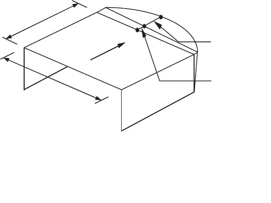
MINIMUM DESIGN LOADS
81
12.3.1.2 Rigid Diaphragm Condition
Diaphragms of concrete slabs or concrete fi lled
metal deck with span-to-depth ratios of 3 or less in
structures that have no horizontal irregularities are
permitted to be idealized as rigid.
12.3.1.3 Calculated Flexible Diaphragm Condition
Diaphragms not satisfying the conditions of
Sections 12.3.1.1 or 12.3.1.2 are permitted to be
idealized as fl exible where the computed maximum
in-plane defl ection of the diaphragm under lateral
load is more than two times the average story drift
of adjoining vertical elements of the seismic force-
resisting system of the associated story under equiva-
lent tributary lateral load as shown in Fig. 12.3-1. The
loadings used for this calculation shall be those
prescribed by Section 12.8.
12.3.2 Irregular and Regular Classifi cation
Structures shall be classifi ed as having a struc-
tural irregularity based upon the criteria in this
section. Such classifi cation shall be based on their
structural confi gurations.
12.3.2.1 Horizontal Irregularity
Structures having one or more of the irregularity
types listed in Table 12.3-1 shall be designated as
having a horizontal structural irregularity. Such
structures assigned to the seismic design categories
listed in Table 12.3-1 shall comply with the require-
ments in the sections referenced in that table.
12.3.2.2 Vertical Irregularity
Structures having one or more of the irregularity
types listed in Table 12.3-2 shall be designated as
having a vertical structural irregularity. Such struc-
tures assigned to the seismic design categories listed
in Table 12.3-2 shall comply with the requirements in
the sections referenced in that table.
EXCEPTIONS:
1. Vertical structural irregularities of Types 1a, 1b,
and 2 in Table 12.3-2 do not apply where no story
drift ratio under design lateral seismic force is
greater than 130 percent of the story drift ratio
of the next story above. Torsional effects need
not be considered in the calculation of story drifts.
The story drift ratio relationship for the top two
stories of the structure are not required to be
evaluated.
2. Vertical structural irregularities of Types 1a, 1b,
and 2 in Table 12.3-2 are not required to be
considered for one-story buildings in any seismic
design category or for two-story buildings assigned
to Seismic Design Categories B, C, or D.
12.3.3 Limitations and Additional Requirements
for Systems with Structural Irregularities
12.3.3.1 Prohibited Horizontal and Vertical
Irregularities for Seismic Design Categories
D through F
Structures assigned to Seismic Design Category E
or F having horizontal irregularity Type 1b of Table
12.3-1 or vertical irregularities Type 1b, 5a, or 5b of
Table 12.3-2 shall not be permitted. Structures
assigned to Seismic Design Category D having
vertical irregularity Type 5b of Table 12.3-2 shall not
be permitted.
12.3.3.2 Extreme Weak Stories
Structures with a vertical irregularity Type 5b as
defi ned in Table 12.3-2, shall not be over two stories
or 30 ft (9 m) in structural height, h
n
.
MAXIMUM DIAPHRAGM
(ADVE)
AVERAGE DRIFT OF VERTICAL ELEMENT
Note: Diaphragm is flexible if MDD > 2(ADVE).
DEFLECTION (MDD)
SEISMIC LOADING
S
De
FIGURE 12.3-1 Flexible Diaphragm
c12.indd 81 4/14/2010 11:02:04 AM

CHAPTER 12 SEISMIC DESIGN REQUIREMENTS FOR BUILDING STRUCTURES
82
Table 12.3-1 Horizontal Structural Irregularities
Type Description Reference Section
Seismic Design
Category Application
1a. Torsional Irregularity: Torsional irregularity is defi ned to exist where the
maximum story drift, computed including accidental torsion with A
x
= 1.0,
at one end of the structure transverse to an axis is more than 1.2 times the
average of the story drifts at the two ends of the structure. Torsional
irregularity requirements in the reference sections apply only to structures
in which the diaphragms are rigid or semirigid.
12.3.3.4
12.7.3
12.8.4.3
12.12.1
Table 12.6-1
Section 16.2.2
D, E, and F
B, C, D, E, and F
C, D, E, and F
C, D, E, and F
D, E, and F
B, C, D, E, and F
1b. Extreme Torsional Irregularity: Extreme torsional irregularity is defi ned
to exist where the maximum story drift, computed including accidental
torsion with A
x
= 1.0, at one end of the structure transverse to an axis is
more than 1.4 times the average of the story drifts at the two ends of the
structure. Extreme torsional irregularity requirements in the reference
sections apply only to structures in which the diaphragms are rigid or
semirigid.
12.3.3.1
12.3.3.4
12.7.3
12.8.4.3
12.12.1
Table 12.6-1
Section 16.2.2
E and F
D
B, C, and D
C and D
C and D
D
B, C, and D
2. Reentrant Corner Irregularity: Reentrant corner irregularity is defi ned to
exist where both plan projections of the structure beyond a reentrant corner
are greater than 15% of the plan dimension of the structure in the given
direction.
12.3.3.4
Table 12.6-1
D, E, and F
D, E, and F
3. Diaphragm Discontinuity Irregularity: Diaphragm discontinuity
irregularity is defi ned to exist where there is a diaphragm with an abrupt
discontinuity or variation in stiffness, including one having a cutout or open
area greater than 50% of the gross enclosed diaphragm area, or a change in
effective diaphragm stiffness of more than 50% from one story to the next.
12.3.3.4
Table 12.6-1
D, E, and F
D, E, and F
4. Out-of-Plane Offset Irregularity: Out-of-plane offset irregularity is
defi ned to exist where there is a discontinuity in a lateral force-resistance
path, such as an out-of-plane offset of at least one of the vertical elements.
12.3.3.3
12.3.3.4
12.7.3
Table 12.6-1
Section 16.2.2
B, C, D, E, and F
D, E, and F
B, C, D, E, and F
D, E, and F
B, C, D, E, and F
5. Nonparallel System Irregularity: Nonparallel system irregularity is
defi ned to exist where vertical lateral force-resisting elements are not
parallel to the major orthogonal axes of the seismic force-resisting system.
12.5.3
12.7.3
Table 12.6-1
Section 16.2.2
C, D, E, and F
B, C, D, E, and F
D, E, and F
B, C, D, E, and F
EXCEPTION: The limit does not apply where
the “weak” story is capable of resisting a total seismic
force equal to Ω
0
times the design force prescribed in
Section 12.8.
12.3.3.3 Elements Supporting Discontinuous Walls
or Frames
Columns, beams, trusses, or slabs supporting
discontinuous walls or frames of structures having
horizontal irregularity Type 4 of Table 12.3-1 or vertical
irregularity Type 4 of Table 12.3-2 shall be designed to
resist the seismic load effects including overstrength
factor of Section 12.4.3. The connections of such
discontinuous elements to the supporting members shall
be adequate to transmit the forces for which the discon-
tinuous elements were required to be designed.
12.3.3.4 Increase in Forces Due to Irregularities for
Seismic Design Categories D through F
For structures assigned to Seismic Design
Category D, E, or F and having a horizontal structural
irregularity of Type 1a, 1b, 2, 3, or 4 in Table 12.3-1
or a vertical structural irregularity of Type 4 in Table
12.3-2, the design forces determined from Section
12.10.1.1 shall be increased 25 percent for the
following elements of the seismic force-resisting
system:
1. Connections of diaphragms to vertical elements
and to collectors.
2. Collectors and their connections, including
connections to vertical elements, of the seismic
force-resisting system.
c12.indd 82 4/14/2010 11:02:04 AM

MINIMUM DESIGN LOADS
83
EXCEPTION:
Forces calculated using the seismic load effects
including overstrength factor of Section 12.4.3 need
not be increased.
12.3.4 Redundancy
A redundancy factor, ρ, shall be assigned to the
seismic force-resisting system in each of two orthogo-
nal directions for all structures in accordance with this
section.
12.3.4.1 Conditions Where Value of ρ is 1.0
The value of ρ is permitted to equal 1.0 for the
following:
1. Structures assigned to Seismic Design Category B
or C.
2. Drift calculation and P-delta effects.
3. Design of nonstructural components.
4. Design of nonbuilding structures that are not
similar to buildings.
5. Design of collector elements, splices, and their
connections for which the seismic load effects
including overstrength factor of Section 12.4.3 are
used.
6. Design of members or connections where the
seismic load effects including overstrength factor
of Section 12.4.3 are required for design.
7. Diaphragm loads determined using Eq. 12.10-1.
8. Structures with damping systems designed in
accordance with Chapter 18.
9. Design of structural walls for out-of-plane forces,
including their anchorage.
Table 12.3-2 Vertical Structural Irregularities
Type Description Reference Section
Seismic Design
Category Application
1a. Stiffness-Soft Story Irregularity: Stiffness-soft story irregularity is
defi ned to exist where there is a story in which the lateral stiffness is less
than 70% of that in the story above or less than 80% of the average
stiffness of the three stories above.
Table 12.6-1 D, E, and F
1b. Stiffness-Extreme Soft Story Irregularity: Stiffness-extreme soft story
irregularity is defi ned to exist where there is a story in which the lateral
stiffness is less than 60% of that in the story above or less than 70% of the
average stiffness of the three stories above.
12.3.3.1
Table 12.6-1
E and F
D, E, and F
2. Weight (Mass) Irregularity: Weight (mass) irregularity is defi ned to exist
where the effective mass of any story is more than 150% of the effective
mass of an adjacent story. A roof that is lighter than the fl oor below need
not be considered.
Table 12.6-1 D, E, and F
3. Vertical Geometric Irregularity: Vertical geometric irregularity is defi ned
to exist where the horizontal dimension of the seismic force-resisting
system in any story is more than 130% of that in an adjacent story.
Table 12.6-1 D, E, and F
4. In-Plane Discontinuity in Vertical Lateral Force-Resisting Element
Irregularity: In-plane discontinuity in vertical lateral force-resisting
elements irregularity is defi ned to exist where there is an in-plane offset of
a vertical seismic force-resisting element resulting in overturning demands
on a supporting beam, column, truss, or slab.
12.3.3.3
12.3.3.4
Table 12.6-1
B, C, D, E, and F
D, E, and F
D, E, and F
5a. Discontinuity in Lateral Strength–Weak Story Irregularity:
Discontinuity in lateral strength–weak story irregularity is defi ned to exist
where the story lateral strength is less than 80% of that in the story above.
The story lateral strength is the total lateral strength of all seismic-resisting
elements sharing the story shear for the direction under consideration.
12.3.3.1
Table 12.6-1
E and F
D, E, and F
5b. Discontinuity in Lateral Strength–Extreme Weak Story Irregularity:
Discontinuity in lateral strength–extreme weak story irregularity is defi ned
to exist where the story lateral strength is less than 65% of that in the story
above. The story strength is the total strength of all seismic-resisting
elements sharing the story shear for the direction under consideration.
12.3.3.1
12.3.3.2
Table 12.6-1
D, E, and F
B and C
D, E, and F
c12.indd 83 4/14/2010 11:02:04 AM

CHAPTER 12 SEISMIC DESIGN REQUIREMENTS FOR BUILDING STRUCTURES
84
12.3.4.2 Redundancy Factor, ρ, for Seismic Design
Categories D through F
For structures assigned to Seismic Design
Category D, E, or F, ρ shall equal 1.3 unless one of
the following two conditions is met, whereby ρ is
permitted to be taken as 1.0:
a. Each story resisting more than 35 percent of the
base shear in the direction of interest shall comply
with Table 12.3-3.
b. Structures that are regular in plan at all levels
provided that the seismic force-resisting systems
consist of at least two bays of seismic force-resisting
perimeter framing on each side of the structure in
each orthogonal direction at each story resisting
more than 35 percent of the base shear. The number
of bays for a shear wall shall be calculated as the
length of shear wall divided by the story height or
two times the length of shear wall divided by the
story height, h
sx
, for light-frame construction.
12.4 SEISMIC LOAD EFFECTS
AND COMBINATIONS
12.4.1 Applicability
All members of the structure, including those not
part of the seismic force-resisting system, shall be
designed using the seismic load effects of Section
12.4 unless otherwise exempted by this standard.
Seismic load effects are the axial, shear, and fl exural
member forces resulting from application of horizon-
tal and vertical seismic forces as set forth in Section
12.4.2. Where specifi cally required, seismic load
effects shall be modifi ed to account for overstrength,
as set forth in Section 12.4.3.
12.4.2 Seismic Load Effect
The seismic load effect, E, shall be determined in
accordance with the following:
1. For use in load combination 5 in Section 2.3.2 or
load combinations 5 and 6 in Section 2.4.1, E shall
be determined in accordance with Eq. 12.4-1 as
follows:
E = E
h
+ E
v
(12.4-1)
2. For use in load combination 7 in Section 2.3.2 or
load combination 8 in Section 2.4.1, E shall be
determined in accordance with Eq. 12.4-2 as follows:
E = E
h
– E
v
(12.4-2)
where
E = seismic load effect
E
h
= effect of horizontal seismic forces as defi ned in
Section 12.4.2.1
E
v
= effect of vertical seismic forces as defi ned in
Section 12.4.2.2
12.4.2.1 Horizontal Seismic Load Effect
The horizontal seismic load effect, E
h
, shall be
determined in accordance with Eq. 12.4-3 as follows:
E
h
= ρQ
E
(12.4-3)
Table 12.3-3 Requirements for Each Story Resisting More than 35% of the Base Shear
Lateral Force-Resisting Element Requirement
Braced frames Removal of an individual brace, or connection thereto, would not result in more than a 33%
reduction in story strength, nor does the resulting system have an extreme torsional
irregularity (horizontal structural irregularity Type 1b).
Moment frames Loss of moment resistance at the beam-to-column connections at both ends of a single beam
would not result in more than a 33% reduction in story strength, nor does the resulting
system have an extreme torsional irregularity (horizontal structural irregularity Type 1b).
Shear walls or wall piers with
a height-to-length ratio greater
than 1.0
Removal of a shear wall or wall pier with a height-to-length ratio greater than 1.0 within
any story, or collector connections thereto, would not result in more than a 33% reduction
in story strength, nor does the resulting system have an extreme torsional irregularity
(horizontal structural irregularity Type 1b). The shear wall and wall pier height-to-length
ratios are determined as shown in Figure 12.3-2.
Cantilever columns Loss of moment resistance at the base connections of any single cantilever column would
not result in more than a 33% reduction in story strength, nor does the resulting system
have an extreme torsional irregularity (horizontal structural irregularity Type 1b).
Other No requirements
c12.indd 84 4/14/2010 11:02:04 AM

MINIMUM DESIGN LOADS
85
Shear wall height-to-length-
ratio = h
wall
/L
wall
Wall pier height-to-length-
ratio = h
wp
/L
wp
h
wall
= height of shear wall
h
wp
= height of wall pier
L
wall
= height of shear wall
L
wp
= height of wall pier
Story Level
Story Level
h
wP
L
wP
h
wall
L
wall
FIGURE 12.3-2 Shear Wall and Wall Pier Height-To-Length Ratio Determination
c12.indd 85 4/14/2010 11:02:04 AM

CHAPTER 12 SEISMIC DESIGN REQUIREMENTS FOR BUILDING STRUCTURES
86
where
Q
E
= effects of horizontal seismic forces from V or F
p
.
Where required by Section 12.5.3 or 12.5.4,
such effects shall result from application of
horizontal forces simultaneously in two direc-
tions at right angles to each other
ρ = redundancy factor, as defi ned in Section 12.3.4
12.4.2.2 Vertical Seismic Load Effect
The vertical seismic load effect, E
v
, shall be
determined in accordance with Eq. 12.4-4 as follows:
E
v
= 0.2S
DS
D (12.4-4)
where
S
DS
= design spectral response acceleration parameter
at short periods obtained from Section 11.4.4
D = effect of dead load
EXCEPTIONS: The vertical seismic load effect,
E
v
, is permitted to be taken as zero for either of the
following conditions:
1. In Eqs. 12.4-1, 12.4-2, 12.4-5, and 12.4-6 where
S
DS
is equal to or less than 0.125.
2. In Eq. 12.4-2 where determining demands on the
soil–structure interface of foundations.
12.4.2.3 Seismic Load Combinations
Where the prescribed seismic load effect, E,
defi ned in Section 12.4.2 is combined with the effects
of other loads as set forth in Chapter 2, the following
seismic load combinations for structures not subject to
fl ood or atmospheric ice loads shall be used in lieu of
the seismic load combinations in either Section 2.3.2
or 2.4.1:
Basic Combinations for Strength Design (see
Sections 2.3.2 and 2.2 for notation).
5. (1.2 + 0.2S
DS
)D + ρQ
E
+ L + 0.2S
6. (0.9 – 0.2S
DS
)D + ρQ
E
+ 1.6H
NOTES:
1. The load factor on L in combination 5 is permitted
to equal 0.5 for all occupancies in which L
o
in
Table 4-1 is less than or equal to 100 psf
(4.79 kN/m
2
), with the exception of garages or
areas occupied as places of public assembly.
2. The load factor on H shall be set equal to zero in
combination 7 if the structural action due to H
counteracts that due to E. Where lateral earth
pressure provides resistance to structural actions
from other forces, it shall not be included in H but
shall be included in the design resistance.
Basic Combinations for Allowable Stress Design
(see Sections 2.4.1 and 2.2 for notation).
5. (1.0 + 0.14S
DS
)D + H + F + 0.7ρQ
E
6. (1.0 + 0.10S
DS
)D + H + F + 0.525ρQ
E
+ 0.75L +
0.75(L
r
or S or R)
8. (0.6 – 0.14S
DS
)D + 0.7ρQ
E
+ H
12.4.3 Seismic Load Effect Including
Overstrength Factor
Where specifi cally required, conditions requiring
overstrength factor applications shall be determined in
accordance with the following:
1. For use in load combination 5 in Section 2.3.2 or
load combinations 5 and 6 in Section 2.4.1, E shall
be taken equal to E
m
as determined in accordance
with Eq. 12.4-5 as follows:
E
m
= E
mh
+ E
v
(12.4-5)
2. For use in load combination 7 in Section 2.3.2 or
load combination 8 in Section 2.4.1, E shall be
taken equal to E
m
as determined in accordance with
Eq. 12.4-6 as follows:
E
m
= E
mh
– E
v
(12.4-6)
where
E
m
= seismic load effect including overstrength factor
E
mh
= effect of horizontal seismic forces including
overstrength factor as defi ned in Section
12.4.3.1
E
v
= vertical seismic load effect as defi ned in Section
12.4.2.2
12.4.3.1 Horizontal Seismic Load Effect with
Overstrength Factor
The horizontal seismic load effect with over-
strength factor, E
mh
, shall be determined in accordance
with Eq. 12.4-7 as follows:
E
mh
= Ω
o
Q
E
(12.4-7)
where
Q
E
= effects of horizontal seismic forces from V, F
px
,
or F
p
as specifi ed in Sections 12.8.1, 12.10, or
13.3.1. Where required by Section 12.5.3 or
12.5.4, such effects shall result from application
of horizontal forces simultaneously in two
directions at right angles to each other.
Ω
o
= overstrength factor
EXCEPTION: The value of E
mh
need not exceed
the maximum force that can develop in the element as
determined by a rational, plastic mechanism analysis
c12.indd 86 4/14/2010 11:02:04 AM

MINIMUM DESIGN LOADS
87
or nonlinear response analysis utilizing realistic
expected values of material strengths.
12.4.3.2 Load Combinations with
Overstrength Factor
Where the seismic load effect with overstrength
factor, E
m
, defi ned in Section 12.4.3, is combined with
the effects of other loads as set forth in Chapter 2, the
following seismic load combination for structures not
subject to fl ood or atmospheric ice loads shall be used
in lieu of the seismic load combinations in either
Section 2.3.2 or 2.4.1:
Basic Combinations for Strength Design with
Overstrength Factor (see Sections 2.3.2 and 2.2 for
notation).
5. (1.2 + 0.2S
DS
)D + Ω
o
Q
E
+ L + 0.2S
7. (0.9 – 0.2S
DS
)D + Ω
o
Q
E
+ 1.6H
NOTES:
1. The load factor on L in combination 5 is permitted
to equal 0.5 for all occupancies in which L
o
in
Table 4-1 is less than or equal to 100 psf (4.79 kN/
m
2
), with the exception of garages or areas
occupied as places of public assembly.
2. The load factor on H shall be set equal to zero in
combination 7 if the structural action due to H
counteracts that due to E. Where lateral earth
pressure provides resistance to structural actions
from other forces, it shall not be included in H but
shall be included in the design resistance.
Basic Combinations for Allowable Stress Design
with Overstrength Factor (see Sections 2.4.1 and
2.2 for notation).
5. (1.0 + 0.14S
DS
)D + H + F + 0.7Ω
o
Q
E
6. (1.0 + 0.105S
DS
)D + H + F + 0.525Ω
o
Q
E
+ 0.75L +
0.75(L
r
or S or R)
8. (0.6 – 0.14S
DS
)D + 0.7Ω
o
Q
E
+ H
12.4.3.3 Allowable Stress Increase for Load
Combinations with Overstrength
Where allowable stress design methodologies are
used with the seismic load effect defi ned in Section
12.4.3 applied in load combinations 5, 6, or 8 of
Section 2.4.1, allowable stresses are permitted to
be determined using an allowable stress increase of
1.2. This increase shall not be combined with
increases in allowable stresses or load combination
reductions otherwise permitted by this standard or
the material reference document except for increases
due to adjustment factors in accordance with AF&PA
NDS.
12.4.4 Minimum Upward Force for Horizontal
Cantilevers for Seismic Design Categories
D through F
In structures assigned to Seismic Design Category
D, E, or F, horizontal cantilever structural members
shall be designed for a minimum net upward force of
0.2 times the dead load in addition to the applicable
load combinations of Section 12.4.
12.5 DIRECTION OF LOADING
12.5.1 Direction of Loading Criteria
The directions of application of seismic forces
used in the design shall be those which will produce
the most critical load effects. It is permitted to satisfy
this requirement using the procedures of Section
12.5.2 for Seismic Design Category B, Section 12.5.3
for Seismic Design Category C, and Section 12.5.4
for Seismic Design Categories D, E, and F.
12.5.2 Seismic Design Category B
For structures assigned to Seismic Design
Category B, the design seismic forces are permitted to
be applied independently in each of two orthogonal
directions and orthogonal interaction effects are
permitted to be neglected.
12.5.3 Seismic Design Category C
Loading applied to structures assigned to Seismic
Design Category C shall, as a minimum, conform to
the requirements of Section 12.5.2 for Seismic Design
Category B and the requirements of this section.
Structures that have horizontal structural irregularity
Type 5 in Table 12.3-1 shall use one of the following
procedures:
a. Orthogonal Combination Procedure. The
structure shall be analyzed using the equivalent
lateral force analysis procedure of Section 12.8, the
modal response spectrum analysis procedure of
Section 12.9, or the linear response history
procedure of Section 16.1, as permitted under
Section 12.6, with the loading applied indepen-
dently in any two orthogonal directions. The
requirement of Section 12.5.1 is deemed satisfi ed if
members and their foundations are designed for
100 percent of the forces for one direction plus 30
percent of the forces for the perpendicular direc-
tion. The combination requiring the maximum
component strength shall be used.
b. Simultaneous Application of Orthogonal
Ground Motion. The structure shall be analyzed
c12.indd 87 4/14/2010 11:02:04 AM

CHAPTER 12 SEISMIC DESIGN REQUIREMENTS FOR BUILDING STRUCTURES
88
using the linear response history procedure of
Section 16.1 or the nonlinear response history
procedure of Section 16.2, as permitted by Section
12.6, with orthogonal pairs of ground motion
acceleration histories applied simultaneously.
12.5.4 Seismic Design Categories D through F
Structures assigned to Seismic Design Category
D, E, or F shall, as a minimum, conform to the
requirements of Section 12.5.3. In addition, any
column or wall that forms part of two or more
intersecting seismic force-resisting systems and is
subjected to axial load due to seismic forces acting
along either principal plan axis equaling or exceeding
20 percent of the axial design strength of the column
or wall shall be designed for the most critical load
effect due to application of seismic forces in any
direction. Either of the procedures of Section 12.5.3 a
or b are permitted to be used to satisfy this require-
ment. Except as required by Section 12.7.3, 2-D
analyses are permitted for structures with fl exible
diaphragms.
12.6 ANALYSIS PROCEDURE SELECTION
The structural analysis required by Chapter 12 shall
consist of one of the types permitted in Table 12.6-1,
based on the structure’s seismic design category,
structural system, dynamic properties, and regularity,
or with the approval of the authority having jurisdic-
tion, an alternative generally accepted procedure is
permitted to be used. The analysis procedure selected
shall be completed in accordance with the require-
ments of the corresponding section referenced in
Table 12.6-1.
12.7 MODELING CRITERIA
12.7.1 Foundation Modeling
For purposes of determining seismic loads, it is
permitted to consider the structure to be fi xed at the
base. Alternatively, where foundation fl exibility is
considered, it shall be in accordance with Section
12.13.3 or Chapter 19.
12.7.2 Effective Seismic Weight
The effective seismic weight, W, of a structure
shall include the dead load, as defi ned in Section 3.1,
above the base and other loads above the base as
listed below:
1. In areas used for storage, a minimum of 25 percent
of the fl oor live load shall be included.
EXCEPTIONS:
a. Where the inclusion of storage loads adds no
more than 5% to the effective seismic weight at
that level, it need not be included in the
effective seismic weight.
b. Floor live load in public garages and open
parking structures need not be included.
Table 12.6-1 Permitted Analytical Procedures
Seismic
Design
Category Structural Characteristics
Equivalent Lateral
Force Analysis,
Section 12.8
a
Modal Response
Spectrum Analysis,
Section 12.9
a
Seismic Response
History Procedures,
Chapter 16
a
B, C All structures P P P
D, E, F Risk Category I or II buildings not exceeding 2
stories above the base
PP P
Structures of light frame construction P P P
Structures with no structural irregularities and not
exceeding 160 ft in structural height
PP P
Structures exceeding 160 ft in structural height
with no structural irregularities and with T < 3.5T
s
PP P
Structures not exceeding 160 ft in structural
height and having only horizontal irregularities of
Type 2, 3, 4, or 5 in Table 12.3-1 or vertical
irregularities of Type 4, 5a, or 5b in Table 12.3-2
PP P
All other structures NP P P
a
P: Permitted; NP: Not Permitted; T
s
= S
D1
/S
DS
.
c12.indd 88 4/14/2010 11:02:04 AM

MINIMUM DESIGN LOADS
89
2. Where provision for partitions is required by
Section 4.2.2 in the fl oor load design, the
actual partition weight or a minimum weight
of 10 psf (0.48 kN/m
2
) of fl oor area, whichever is
greater.
3. Total operating weight of permanent equipment.
4. Where the fl at roof snow load, P
f
, exceeds 30 psf
(1.44 kN/m
2
), 20 percent of the uniform design
snow load, regardless of actual roof slope.
5. Weight of landscaping and other materials at roof
gardens and similar areas.
12.7.3 Structural Modeling
A mathematical model of the structure shall be
constructed for the purpose of determining member
forces and structure displacements resulting from
applied loads and any imposed displacements or
P-delta effects. The model shall include the stiffness
and strength of elements that are signifi cant to the
distribution of forces and deformations in the structure
and represent the spatial distribution of mass and
stiffness throughout the structure.
In addition, the model shall comply with the
following:
a. Stiffness properties of concrete and masonry
elements shall consider the effects of cracked
sections.
b. For steel moment frame systems, the contribution
of panel zone deformations to overall story drift
shall be included.
Structures that have horizontal structural irregu-
larity Type 1a, 1b, 4, or 5 of Table 12.3-1 shall be
analyzed using a 3-D representation. Where a 3-D
model is used, a minimum of three dynamic degrees
of freedom consisting of translation in two orthogonal
plan directions and rotation about the vertical axis
shall be included at each level of the structure. Where
the diaphragms have not been classifi ed as rigid or
fl exible in accordance with Section 12.3.1, the model
shall include representation of the diaphragm’s
stiffness characteristics and such additional dynamic
degrees of freedom as are required to account for the
participation of the diaphragm in the structure’s
dynamic response.
EXCEPTION: Analysis using a 3-D
representation is not required for structures with
fl exible diaphragms that have Type 4 horizontal
structural irregularities.
12.7.4 Interaction Effects
Moment-resisting frames that are enclosed or
adjoined by elements that are more rigid and not
considered to be part of the seismic force-resisting
system shall be designed so that the action or
failure of those elements will not impair the vertical
load and seismic force-resisting capability of the
frame. The design shall provide for the effect of
these rigid elements on the structural system at
structural deformations corresponding to the design
story drift (Δ) as determined in Section 12.8.6. In
addition, the effects of these elements shall be
considered where determining whether a structure
has one or more of the irregularities defi ned in
Section 12.3.2.
12.8 EQUIVALENT LATERAL
FORCE PROCEDURE
12.8.1 Seismic Base Shear
The seismic base shear, V, in a given direction
shall be determined in accordance with the following
equation:
V = C
s
W (12.8-1)
where
C
s
= the seismic response coeffi cient determined in
accordance with Section 12.8.1.1
W = the effective seismic weight per Section 12.7.2
12.8.1.1 Calculation of Seismic Response Coeffi cient
The seismic response coeffi cient, C
s
, shall be
determined in accordance with Eq. 12.8-2.
C
S
R
I
s
DS
e
=
⎛
⎝
⎜
⎞
⎠
⎟
(12.8-2)
where
S
DS
= the design spectral response acceleration
parameter in the short period range as deter-
mined from Section 11.4.4 or 11.4.7
R = the response modifi cation factor in Table 12.2-1
I
e
= the importance factor determined in accordance
with Section 11.5.1
The value of C
s
computed in accordance with Eq.
12.8-2 need not exceed the following:
C
S
T
R
I
s
D
e
=
⎛
⎝
⎜
⎞
⎠
⎟
1
for T ≤ T
L
(12.8-3)
C
ST
T
R
I
s
DL
e
=
⎛
⎝
⎜
⎞
⎠
⎟
1
2
for T > T
L
(12.8-4)
c12.indd 89 4/14/2010 11:02:05 AM

CHAPTER 12 SEISMIC DESIGN REQUIREMENTS FOR BUILDING STRUCTURES
90
C
s
shall not be less than
C
s
= 0.044S
DS
I
e
≥ 0.01 (12.8-5)
In addition, for structures located where S
1
is equal to
or greater than 0.6g, C
s
shall not be less than
C
s
= 0.5S
1
/(R/I
e
) (12.8-6)
where I
e
and R are as defi ned in Section 12.8.1.1 and
S
D1
= the design spectral response acceleration
parameter at a period of 1.0 s, as determined
from Section 11.4.4 or 11.4.7
T = the fundamental period of the structure(s)
determined in Section 12.8.2
T
L
= long-period transition period(s) determined in
Section 11.4.5
S
1
= the mapped maximum considered earthquake
spectral response acceleration parameter
determined in accordance with Section 11.4.1
or 11.4.7
12.8.1.2 Soil Structure Interaction Reduction
A soil structure interaction reduction is permitted
where determined using Chapter 19 or other generally
accepted procedures approved by the authority having
jurisdiction.
12.8.1.3 Maximum S
s
Value in Determination of C
s
For regular structures fi ve stories or less above
the base as defi ned in Section 11.2 and with a period,
T, of 0.5 s or less, C
s
is permitted to be calculated
using a value of 1.5 for S
S
.
12.8.2 Period Determination
The fundamental period of the structure, T, in the
direction under consideration shall be established
using the structural properties and deformational
characteristics of the resisting elements in a properly
substantiated analysis. The fundamental period, T,
shall not exceed the product of the coeffi cient for
upper limit on calculated period (C
u
) from Table
12.8-1 and the approximate fundamental period, T
a
,
determined in accordance with Section 12.8.2.1. As an
alternative to performing an analysis to determine the
fundamental period, T, it is permitted to use the
approximate building period, T
a
, calculated in accor-
dance with Section 12.8.2.1, directly.
12.8.2.1 Approximate Fundamental Period
The approximate fundamental period (T
a
), in s,
shall be determined from the following equation:
T
a
= C
t
h
n
x
(12.8-7)
where h
n
is the structural height as defi ned in Section
11.2 and the coeffi cients C
t
and x are determined from
Table 12.8-2.
Alternatively, it is permitted to determine the
approximate fundamental period (T
a
), in s, from the
following equation for structures not exceeding 12
stories above the base as defi ned in Section 11.2
where the seismic force-resisting system consists
Table 12.8-1 Coeffi cient for Upper Limit on
Calculated Period
Design Spectral Response Acceleration
Parameter at 1 s, S
D1
Coeffi cient C
u
≥ 0.4 1.4
0.3 1.4
0.2 1.5
0.15 1.6
≤ 0.1 1.7
Table 12.8-2 Values of Approximate Period Parameters C
t
and x
Structure Type C
t
x
Moment-resisting frame systems in which the frames resist 100% of the required seismic force
and are not enclosed or adjoined by components that are more rigid and will prevent the frames
from defl ecting where subjected to seismic forces:
Steel moment-resisting frames
0.028 (0.0724)
a
0.8
Concrete moment-resisting frames
0.016 (0.0466)
a
0.9
Steel eccentrically braced frames in accordance with Table 12.2-1 lines B1 or D1
0.03 (0.0731)
a
0.75
Steel buckling-restrained braced frames
0.03 (0.0731)
a
0.75
All other structural systems
0.02 (0.0488)
a
0.75
a
Metric equivalents are shown in parentheses.
c12.indd 90 4/14/2010 11:02:05 AM

MINIMUM DESIGN LOADS
91
entirely of concrete or steel moment resisting frames
and the average story height is at least 10 ft (3 m):
T
a
= 0.1N (12.8-8)
where N = number of stories above the base.
The approximate fundamental period, T
a
, in s for
masonry or concrete shear wall structures is permitted
to be determined from Eq. 12.8-9 as follows:
T
C
h
a
w
n
=
0 0019.
(12.8-9)
where C
w
is calculated from Eq. 12.8-10 as follows:
C
A
h
h
A
h
D
w
B
n
i
i
x
i
i
i
=
⎛
⎝
⎜
⎞
⎠
⎟
+
⎛
⎝
⎜
⎞
⎠
⎟
⎡
⎣
⎢
⎤
⎦
⎥
=
∑
100
1083
1
2
2
.
(12.8-10)
where
A
B
= area of base of structure, ft
2
A
i
= web area of shear wall i in ft
2
D
i
= length of shear wall i in ft
h
i
= height of shear wall i in ft
x = number of shear walls in the building effective
in resisting lateral forces in the direction under
consideration
12.8.3 Vertical Distribution of Seismic Forces
The lateral seismic force (F
x
) (kip or kN) induced
at any level shall be determined from the following
equations:
F
x
= C
vx
V (12.8-11)
and
C
wh
wh
vx
xx
k
ii
k
i
n
=
=
∑
1
(12.8-12)
where
C
vx
= vertical distribution factor
V = total design lateral force or shear at the
base of the structure (kip or kN)
w
i
and w
x
= the portion of the total effective seismic
weight of the structure (W) located or
assigned to Level i or x
h
i
and h
x
= the height (ft or m) from the base to
Level i or x
k = an exponent related to the structure period
as follows:
for structures having a period of 0.5 s or
less, k = 1
for structures having a period of 2.5 s or
more, k = 2
for structures having a period between 0.5
and 2.5 s, k shall be 2 or shall be
determined by linear interpolation
between 1 and 2
12.8.4 Horizontal Distribution of Forces
The seismic design story shear in any story (V
x
)
(kip or kN) shall be determined from the following
equation:
VF
xi
ix
n
=
=
∑
(12.8-13)
where F
i
= the portion of the seismic base shear (V)
(kip or kN) induced at Level i.
The seismic design story shear (V
x
) (kip or kN)
shall be distributed to the various vertical elements of
the seismic force-resisting system in the story under
consideration based on the relative lateral stiffness of
the vertical resisting elements and the diaphragm.
12.8.4.1 Inherent Torsion
For diaphragms that are not fl exible, the distribu-
tion of lateral forces at each level shall consider the
effect of the inherent torsional moment, M
t
, resulting
from eccentricity between the locations of the center
of mass and the center of rigidity. For fl exible
diaphragms, the distribution of forces to the vertical
elements shall account for the position and distribu-
tion of the masses supported.
12.8.4.2 Accidental Torsion
Where diaphragms are not fl exible, the design
shall include the inherent torsional moment (M
t
)
resulting from the location of the structure masses
plus the accidental torsional moments (M
ta
) caused by
assumed displacement of the center of mass each way
from its actual location by a distance equal to 5
percent of the dimension of the structure perpendicu-
lar to the direction of the applied forces.
Where earthquake forces are applied concurrently
in two orthogonal directions, the required 5 percent
displacement of the center of mass need not be
applied in both of the orthogonal directions at the
same time, but shall be applied in the direction that
produces the greater effect.
12.8.4.3 Amplifi cation of Accidental
Torsional Moment
Structures assigned to Seismic Design Category
C, D, E, or F, where Type 1a or 1b torsional irregu-
larity exists as defi ned in Table 12.3-1 shall have the
effects accounted for by multiplying M
ta
at each level
by a torsional amplifi cation factor (A
x
) as illustrated in
c12.indd 91 4/14/2010 11:02:05 AM

CHAPTER 12 SEISMIC DESIGN REQUIREMENTS FOR BUILDING STRUCTURES
92
Fig. 12.8-1 and determined from the following
equation:
A
x
=
⎛
⎝
⎜
⎞
⎠
⎟
δ
δ
max
.12
2
avg
(12.8-14)
where
δ
max
= the maximum displacement at Level x com-
puted assuming A
x
= 1 (in. or mm)
δ
avg
= the average of the displacements at the extreme
points of the structure at Level x computed
assuming A
x
= 1 (in. or mm)
The torsional amplifi cation factor (A
x
) shall not
be less than 1 and is not required to exceed 3.0. The
more severe loading for each element shall be
considered for design.
12.8.5 Overturning
The structure shall be designed to resist overturn-
ing effects caused by the seismic forces determined in
Section 12.8.3.
12.8.6 Story Drift Determination
The design story drift (Δ) shall be computed as
the difference of the defl ections at the centers of mass
at the top and bottom of the story under consideration.
See Fig. 12.8-2. Where centers of mass do not align
vertically, it is permitted to compute the defl ection at
the bottom of the story based on the vertical projec-
tion of the center of mass at the top of the story.
Where allowable stress design is used, Δ shall be
computed using the strength level seismic forces
specifi ed in Section 12.8 without reduction for
allowable stress design.
For structures assigned to Seismic Design
Category C, D, E, or F having horizontal irregularity
Type 1a or 1b of Table 12.3-1, the design story drift,
Δ, shall be computed as the largest difference of the
defl ections of vertically aligned points at the top and
bottom of the story under consideration along any of
the edges of the structure.
The defl ection at Level x (δ
x
) (in. or mm) used to
compute the design story drift, Δ, shall be determined
in accordance with the following equation:
δ
δ
x
dxe
e
C
I
=
(12.8-15)
where
C
d
= the defl ection amplifi cation factor in Table
12.2-1
δ
xe
= the defl ection at the location required by this
section determined by an elastic analysis
I
e
= the importance factor determined in accordance
with Section 11.5.1
12.8.6.1 Minimum Base Shear for Computing Drift
The elastic analysis of the seismic force-resisting
system for computing drift shall be made using the
prescribed seismic design forces of Section 12.8.
EXCEPTION: Eq. 12.8-5 need not be
considered for computing drift.
δ
δ
B
2
xavg
A;
2
⎥
⎥
⎦
⎤
⎢
⎢
⎣
⎡
=
+
=
δ
δ
δ
A
2
avg
max
xavg
1.2
δ
A;
2
⎥
⎥
⎦
⎤
⎢
⎢
⎣
⎡
=
+
=
δδ
B
δ
A
δ
FIGURE 12.8-1 Torsional Amplifi cation Factor, A
x
c12.indd 92 4/14/2010 11:02:05 AM

MINIMUM DESIGN LOADS
93
12.8.6.2 Period for Computing Drift
For determining compliance with the story drift
limits of Section 12.12.1, it is permitted to determine
the elastic drifts, (δ
xe
), using seismic design forces
based on the computed fundamental period of the
structure without the upper limit (C
u
T
a
) specifi ed in
Section 12.8.2.
12.8.7 P-Delta Effects
P-delta effects on story shears and moments, the
resulting member forces and moments, and the story
drifts induced by these effects are not required to be
considered where the stability coeffi cient (θ) as
determined by the following equation is equal to or
less than 0.10:
θ=
ΔPI
Vh C
xe
xsx d
(12.8-16)
where
P
x
= the total vertical design load at and above Level
x (kip or kN); where computing P
x
, no individual
load factor need exceed 1.0
Δ = the design story drift as defi ned in Section 12.8.6
occurring simultaneously with V
x
(in. or mm)
I
e
= the importance factor determined in accordance
with Section 11.5.1
V
x
= the seismic shear force acting between Levels x
and x – 1 (kip or kN)
h
sx
= the story height below Level x (in. or mm)
C
d
= the defl ection amplifi cation factor in Table
12.2-1
The stability coeffi cient (θ) shall not exceed θ
max
determined as follows:
θ
β
max
.
.=≤
05
025
C
d
(12.8-17)
where β is the ratio of shear demand to shear capacity
for the story between Levels x and x – 1. This ratio is
permitted to be conservatively taken as 1.0.
Where the stability coeffi cient (θ) is greater than
0.10 but less than or equal to θ
max
, the incremental
factor related to P-delta effects on displacements and
member forces shall be determined by rational
analysis. Alternatively, it is permitted to multiply
displacements and member forces by 1.0/(1 – θ).
Where θ is greater than θ
max
, the structure is
potentially unstable and shall be redesigned.
Where the P-delta effect is included in an
automated analysis, Eq. 12.8-17 shall still be satisfi ed,
however, the value of θ computed from Eq. 12.8-16
using the results of the P-delta analysis is permitted to
be divided by (1 + θ) before checking Eq. 12.8-17.
L
2
L
1
Story Level 2
F
2
= strength-level design earthquake force
δ
δδ
δ
e2
= elastic displacement computed under
strength-level design earthquake forces
δ
δδ
δ
2
= Cd δe2/IE = amplified displacement
Δ
ΔΔ
Δ
2
=
δ
(δ(δ
(δ
e2
-
δ
δδ
δ
e1
)C
d
/I
E
≤
≤≤
≤Δ
ΔΔ
Δ
a
(Table 12.12-1)
Story Level 1
F
1
= strength-level design earthquake force
δ
δδ
δ
e1
= elastic displacement computed under
strength-level design earthquake forces
δ
δδ
δ
1
= C
d
δ
δ δ
δ
e1
/I
E
= amplified displacement
Δ
ΔΔ
Δ
1
=
δδ
δ
1
≤
≤≤
≤Δ
ΔΔ
Δ
a
(Table 12.12-1)
Δ
ΔΔ
Δ
i
= Story Drift
Δ
ΔΔ
Δ
i
/L
i
= Story Drift Ratio
δ
δδ
δ
2
= Total Displacement
e
FIGURE 12.8-2 Story Drift Determination
c12.indd 93 4/14/2010 11:02:05 AM

CHAPTER 12 SEISMIC DESIGN REQUIREMENTS FOR BUILDING STRUCTURES
94
12.9 MODAL RESPONSE
SPECTRUM ANALYSIS
12.9.1 Number of Modes
An analysis shall be conducted to determine the
natural modes of vibration for the structure. The
analysis shall include a suffi cient number of modes to
obtain a combined modal mass participation of at
least 90 percent of the actual mass in each of the
orthogonal horizontal directions of response consid-
ered by the model.
12.9.2 Modal Response Parameters
The value for each force-related design parameter
of interest, including story drifts, support forces, and
individual member forces for each mode of response
shall be computed using the properties of each mode
and the response spectra defi ned in either Section
11.4.5 or 21.2 divided by the quantity R/I
e
. The value
for displacement and drift quantities shall be multi-
plied by the quantity C
d
/I
e
.
12.9.3 Combined Response Parameters
The value for each parameter of interest calcu-
lated for the various modes shall be combined using
the square root of the sum of the squares (SRSS)
method, the complete quadratic combination (CQC)
method, the complete quadratic combination method
as modifi ed by ASCE 4 (CQC-4), or an approved
equivalent approach. The CQC or the CQC-4 method
shall be used for each of the modal values where
closely spaced modes have signifi cant cross-
correlation of translational and torsional response.
12.9.4 Scaling Design Values of
Combined Response
A base shear (V) shall be calculated in each of
the two orthogonal horizontal directions using the
calculated fundamental period of the structure T in
each direction and the procedures of Section 12.8.
12.9.4.1 Scaling of Forces
Where the calculated fundamental period exceeds
C
u
T
a
in a given direction, C
u
T
a
shall be used in lieu of
T in that direction. Where the combined response for
the modal base shear (V
t
) is less than 85 percent of
the calculated base shear (V) using the equivalent
lateral force procedure, the forces shall be multiplied
by 0.85
V
−
Vt
:
where
V = the equivalent lateral force procedure base shear,
calculated in accordance with this section and
Section 12.8
V
t
= the base shear from the required modal
combination
12.9.4.2 Scaling of Drifts
Where the combined response for the modal base
shear (V
t
) is less than 0.85C
s
W, and where C
s
is
determined in accordance with Eq. 12.8-6, drifts shall
be multiplied by
085.
CW
V
s
t
12.9.5 Horizontal Shear Distribution
The distribution of horizontal shear shall be in
accordance with Section 12.8.4 except that amplifi ca-
tion of torsion in accordance with Section 12.8.4.3 is
not required where accidental torsion effects are
included in the dynamic analysis model.
12.9.6 P-Delta Effects
The P-delta effects shall be determined in
accordance with Section 12.8.7. The base shear
used to determine the story shears and the story
drifts shall be determined in accordance with
Section 12.8.6.
12.9.7 Soil Structure Interaction Reduction
A soil structure interaction reduction is permitted
where determined using Chapter 19 or other generally
accepted procedures approved by the authority having
jurisdiction.
12.10 DIAPHRAGMS, CHORDS,
AND COLLECTORS
12.10.1 Diaphragm Design
Diaphragms shall be designed for both the shear
and bending stresses resulting from design forces. At
diaphragm discontinuities, such as openings and
reentrant corners, the design shall assure that the
dissipation or transfer of edge (chord) forces com-
bined with other forces in the diaphragm is within
shear and tension capacity of the diaphragm.
12.10.1.1 Diaphragm Design Forces
Floor and roof diaphragms shall be designed to
resist design seismic forces from the structural
analysis, but shall not be less than that determined in
accordance with Eq. 12.10-1 as follows:
F
F
w
w
px
i
ix
n
i
ix
n
px
=
=
=
∑
∑
(12.10-1)
c12.indd 94 4/14/2010 11:02:05 AM

MINIMUM DESIGN LOADS
95
where
F
px
= the diaphragm design force
F
i
= the design force applied to Level i
w
i
= the weight tributary to Level i
w
px
= the weight tributary to the diaphragm at Level x
The force determined from Eq. 12.10-1 shall not
be less than
F
px
= 0.2S
DS
I
e
w
px
(12.10-2)
The force determined from Eq. 12.10-1 need not
exceed
F
px
= 0.4S
DS
I
e
w
px
(12.10-3)
Where the diaphragm is required to transfer
design seismic force from the vertical resisting
elements above the diaphragm to other vertical
resisting elements below the diaphragm due to offsets
in the placement of the elements or to changes in
relative lateral stiffness in the vertical elements, these
forces shall be added to those determined from Eq.
12.10-1. The redundancy factor, ρ, applies to the
design of diaphragms in structures assigned to
Seismic Design Category D, E, or F. For inertial
forces calculated in accordance with Eq. 12.10-1, the
redundancy factor shall equal 1.0. For transfer forces,
the redundancy factor, ρ, shall be the same as that
used for the structure. For structures having horizontal
or vertical structural irregularities of the types
indicated in Section 12.3.3.4, the requirements of that
section shall also apply.
12.10.2 Collector Elements
Collector elements shall be provided that are
capable of transferring the seismic forces originating
in other portions of the structure to the element
providing the resistance to those forces.
12.10.2.1 Collector Elements Requiring Load
Combinations with Overstrength Factor for Seismic
Design Categories C through F
In structures assigned to Seismic Design Category
C, D, E, or F, collector elements (see Fig. 12.10-1)
and their connections including connections to vertical
elements shall be designed to resist the maximum of
the following:
1. Forces calculated using the seismic load effects
including overstrength factor of Section 12.4.3 with
seismic forces determined by the Equivalent
Lateral Force procedure of Section 12.8 or the
Modal Response Spectrum Analysis procedure of
Section 12.9.
2. Forces calculated using the seismic load effects
including overstrength factor of Section 12.4.3
with seismic forces determined by Equation
12.10-1.
3. Forces calculated using the load combinations of
Section 12.4.2.3 with seismic forces determined by
Equation 12.10-2.
Transfer forces as described in Section 12.10.1.1
shall be considered.
EXCEPTIONS:
1. The forces calculated above need not exceed those
calculated using the load combinations of Section
12.4.2.3 with seismic forces determined by
Equation 12.10-3.
2. In structures or portions thereof braced entirely by
light-frame shear walls, collector elements and
their connections including connections to vertical
elements need only be designed to resist forces
using the load combinations of Section 12.4.2.3
with seismic forces determined in accordance with
Section 12.10.1.1.
FULL LENGTH SHEAR WALL
(NO COLLECTOR REQUIRED)
COLLECTOR ELEMENT TO
TRANSFER FORCE BETWEEN
DIAPHRAGM AND SHEAR WALL
SHEAR WALL AT
STAIRWELL
FIGURE 12.10-1 Collectors
c12.indd 95 4/14/2010 11:02:05 AM

CHAPTER 12 SEISMIC DESIGN REQUIREMENTS FOR BUILDING STRUCTURES
96
12.11 STRUCTURAL WALLS AND
THEIR ANCHORAGE
12.11.1 Design for Out-of-Plane Forces
Structural walls and their anchorage shall be
designed for a force normal to the surface equal to F
p
= 0.4S
DS
I
e
times the weight of the structural wall with
a minimum force of 10 percent of the weight of the
structural wall. Interconnection of structural wall
elements and connections to supporting framing
systems shall have suffi cient ductility, rotational
capacity, or suffi cient strength to resist shrinkage,
thermal changes, and differential foundation settle-
ment when combined with seismic forces.
12.11.2 Anchorage of Structural Walls and
Transfer of Design Forces into Diaphragms.
12.11.2.1 Wall Anchorage Forces
The anchorage of structural walls to supporting
construction shall provide a direct connection capable
of resisting the following:
F
p
= 0.4S
DS
k
a
I
e
W
p
(12.11-1)
F
p
shall not be taken less than 0.2k
a
I
e
W
p
.
k
L
a
f
=+10
100
. (12.11-2)
k
a
need not be taken larger than 2.0.
where
F
p
= the design force in the individual anchors
S
DS
= the design spectral response acceleration
parameter at short periods per Section 11.4.4
I
e
= the importance factor determined in accordance
with Section 11.5.1
k
a
= amplifi cation factor for diaphragm fl exibility
L
f
= the span, in feet, of a fl exible diaphragm that
provides the lateral support for the wall; the span is
measured between vertical elements that provide
lateral support to the diaphragm in the direction
considered; use zero for rigid diaphragms
W
p
= the weight of the wall tributary to the anchor
Where the anchorage is not located at the roof
and all diaphragms are not fl exible, the value from
Eq. 12.11-1 is permitted to be multiplied by the factor
(1 + 2z/h)/3, where z is the height of the anchor above
the base of the structure and h is the height of the roof
above the base.
Structural walls shall be designed to resist
bending between anchors where the anchor spacing
exceeds 4 ft (1,219 mm).
12.11.2.2 Additional Requirements for Diaphragms
in Structures Assigned to Seismic Design Categories
C through F
12.11.2.2.1 Transfer of Anchorage Forces into
Diaphragm Diaphragms shall be provided with
continuous ties or struts between diaphragm chords to
distribute these anchorage forces into the diaphragms.
Diaphragm connections shall be positive, mechanical,
or welded. Added chords are permitted to be used to
form subdiaphragms to transmit the anchorage forces
to the main continuous cross-ties. The maximum
length-to-width ratio of the structural subdiaphragm
shall be 2.5 to 1. Connections and anchorages capable
of resisting the prescribed forces shall be provided
between the diaphragm and the attached components.
Connections shall extend into the diaphragm a
suffi cient distance to develop the force transferred into
the diaphragm.
12.11.2.2.2 Steel Elements of Structural Wall Anchor-
age System The strength design forces for steel
elements of the structural wall anchorage system, with
the exception of anchor bolts and reinforcing steel,
shall be increased by 1.4 times the forces otherwise
required by this section.
12.11.2.2.3 Wood Diaphragms In wood diaphragms,
the continuous ties shall be in addition to the dia-
phragm sheathing. Anchorage shall not be accom-
plished by use of toenails or nails subject to
withdrawal nor shall wood ledgers or framing be
used in cross-grain bending or cross-grain tension.
The diaphragm sheathing shall not be considered
effective as providing the ties or struts required by
this section.
12.11.2.2.4 Metal Deck Diaphragms In metal deck
diaphragms, the metal deck shall not be used as the
continuous ties required by this section in the direc-
tion perpendicular to the deck span.
12.11.2.2.5 Embedded Straps Diaphragm to structural
wall anchorage using embedded straps shall be
attached to, or hooked around, the reinforcing steel or
otherwise terminated so as to effectively transfer
forces to the reinforcing steel.
12.11.2.2.6 Eccentrically Loaded Anchorage System
Where elements of the wall anchorage system are
loaded eccentrically or are not perpendicular to the
wall, the system shall be designed to resist all
components of the forces induced by the eccentricity.
c12.indd 96 4/14/2010 11:02:05 AM

MINIMUM DESIGN LOADS
97
12.11.2.2.7 Walls with Pilasters Where pilasters are
present in the wall, the anchorage force at the pilas-
ters shall be calculated considering the additional load
transferred from the wall panels to the pilasters.
However, the minimum anchorage force at a fl oor or
roof shall not be reduced.
12.12 DRIFT AND DEFORMATION
12.12.1 Story Drift Limit
The design story drift (Δ) as determined in
Sections 12.8.6, 12.9.2, or 16.1, shall not exceed the
allowable story drift (Δ
a
) as obtained from Table
12.12-1 for any story.
12.12.1.1 Moment Frames in Structures Assigned to
Seismic Design Categories D through F
For seismic force-resisting systems comprised
solely of moment frames in structures assigned to
Seismic Design Categories D, E, or F, the design
story drift (Δ) shall not exceed Δ
a
/ρ for any story.
ρ shall be determined in accordance with Section
12.3.4.2.
12.12.2 Diaphragm Defl ection
The defl ection in the plane of the diaphragm, as
determined by engineering analysis, shall not exceed
the permissible defl ection of the attached elements.
Permissible defl ection shall be that defl ection that will
permit the attached element to maintain its structural
integrity under the individual loading and continue to
support the prescribed loads.
12.12.3 Structural Separation
All portions of the structure shall be designed and
constructed to act as an integral unit in resisting
seismic forces unless separated structurally by a
distance suffi cient to avoid damaging contact as set
forth in this section.
Separations shall allow for the maximum inelastic
response displacement (δ
M
). δ
M
shall be determined at
critical locations with consideration for translational
and torsional displacements of the structure including
torsional amplifi cations, where applicable, using the
following equation:
δ
δ
M
d
e
C
I
=
max
(12.12-1)
Where δ
max
= maximum elastic displacement at the
critical location.
Adjacent structures on the same property shall be
separated by at least δ
MT
, determined as follows:
δδδ
MT M M
=
()
+
()
1
2
2
2
(12.12-2)
where δ
M1
and δ
M2
are the maximum inelastic response
displacements of the adjacent structures at their
adjacent edges.
Where a structure adjoins a property line not
common to a public way, the structure shall be set
back from the property line by at least the displace-
ment δ
M
of that structure.
EXCEPTION: Smaller separations or property
line setbacks are permitted where justifi ed by rational
analysis based on inelastic response to design ground
motions.
Table 12.12-1 Allowable Story Drift, Δ
a
a,b
Structure
Risk Category
I or II III IV
Structures, other than masonry shear wall structures, 4 stories or less above the base as
defi ned in Section 11.2, with interior walls, partitions, ceilings, and exterior wall systems
that have been designed to accommodate the story drifts.
0.025h
sx
c
0.020h
sx
0.015h
sx
Masonry cantilever shear wall structures
d
0.010h
sx
0.010h
sx
0.010h
sx
Other masonry shear wall structures
0.007h
sx
0.007h
sx
0.007h
sx
All other structures
0.020h
sx
0.015h
sx
0.010h
sx
a
h
sx
is the story height below Level x.
b
For seismic force-resisting systems comprised solely of moment frames in Seismic Design Categories D, E, and F, the allowable story drift shall
comply with the requirements of Section 12.12.1.1.
c
There shall be no drift limit for single-story structures with interior walls, partitions, ceilings, and exterior wall systems that have been designed
to accommodate the story drifts. The structure separation requirement of Section 12.12.3 is not waived.
d
Structures in which the basic structural system consists of masonry shear walls designed as vertical elements cantilevered from their base or
foundation support which are so constructed that moment transfer between shear walls (coupling) is negligible.
c12.indd 97 4/14/2010 11:02:06 AM

CHAPTER 12 SEISMIC DESIGN REQUIREMENTS FOR BUILDING STRUCTURES
98
12.12.4 Members Spanning between Structures
Gravity connections or supports for members
spanning between structures or seismically separate
portions of structures shall be designed for the
maximum anticipated relative displacements. These
displacements shall be calculated:
1. Using the defl ection calculated at the locations of
support, per Eq. 12.8-15 multiplied by 1.5R/C
d
, and
2. Considering additional defl ection due to diaphragm
rotation including the torsional amplifi cation factor
calculated per Section 12.8.4.3 where either
structure is torsionally irregular, and
3. Considering diaphragm deformations, and
4. Assuming the two structures are moving in
opposite directions and using the absolute sum of
the displacements.
12.12.5 Deformation Compatibility for Seismic
Design Categories D through F
For structures assigned to Seismic Design
Category D, E, or F, every structural component not
included in the seismic force-resisting system in the
direction under consideration shall be designed to be
adequate for the gravity load effects and the seismic
forces resulting from displacement due to the design
story drift (Δ) as determined in accordance with
Section 12.8.6 (see also Section 12.12.1).
EXCEPTION: Reinforced concrete frame
members not designed as part of the seismic force-
resisting system shall comply with Section 21.11 of
ACI 318.
Where determining the moments and shears
induced in components that are not included in the
seismic force-resisting system in the direction under
consideration, the stiffening effects of adjoining rigid
structural and nonstructural elements shall be consid-
ered and a rational value of member and restraint
stiffness shall be used.
12.13 FOUNDATION DESIGN
12.13.1 Design Basis
The design basis for foundations shall be as set
forth in Section 12.1.5.
12.13.2 Materials of Construction
Materials used for the design and construction of
foundations shall comply with the requirements of
Chapter 14. Design and detailing of steel piles shall
comply with Section 14.1.7 Design and detailing of
concrete piles shall comply with Section 14.2.3.
12.13.3 Foundation Load-Deformation
Characteristics
Where foundation fl exibility is included for the
linear analysis procedures in Chapters 12 and 16, the
load-deformation characteristics of the foundation–soil
system (foundation stiffness) shall be modeled in
accordance with the requirements of this section.
The linear load-deformation behavior of foundations
shall be represented by an equivalent linear stiffness
using soil properties that are compatible with the
soil strain levels associated with the design
earthquake motion. The strain-compatible shear
modulus, G, and the associated strain-compatible
shear wave velocity, v
S
, needed for the evaluation
of equivalent linear stiffness shall be determined
using the criteria in Section 19.2.1.1 or based on a
site-specifi c study. A 50 percent increase and
decrease in stiffness shall be incorporated in dynamic
analyses unless smaller variations can be justifi ed
based on fi eld measurements of dynamic soil proper-
ties or direct measurements of dynamic foundation
stiffness. The largest values of response shall be used
in design.
12.13.4 Reduction of Foundation Overturning
Overturning effects at the soil–foundation
interface are permitted to be reduced by 25 percent
for foundations of structures that satisfy both of the
following conditions:
a. The structure is designed in accordance with the
Equivalent Lateral Force Analysis as set forth in
Section 12.8.
b. The structure is not an inverted pendulum or
cantilevered column type structure.
Overturning effects at the soil–foundation
interface are permitted to be reduced by 10 percent
for foundations of structures designed in accordance
with the modal analysis requirements of Section 12.9.
12.13.5 Requirements for Structures Assigned to
Seismic Design Category C
In addition to the requirements of Section 11.8.2,
the following foundation design requirements shall
apply to structures assigned to Seismic Design
Category C.
12.13.5.1 Pole-Type Structures
Where construction employing posts or poles as
columns embedded in earth or embedded in concrete
footings in the earth is used to resist lateral loads, the
depth of embedment required for posts or poles to
resist seismic forces shall be determined by means of
c12.indd 98 4/14/2010 11:02:06 AM

MINIMUM DESIGN LOADS
99
the design criteria established in the foundation
investigation report.
12.13.5.2 Foundation Ties
Individual pile caps, drilled piers, or caissons
shall be interconnected by ties. All ties shall have a
design strength in tension or compression at least
equal to a force equal to 10 percent of S
DS
times the
larger pile cap or column factored dead plus factored
live load unless it is demonstrated that equivalent
restraint will be provided by reinforced concrete
beams within slabs on grade or reinforced concrete
slabs on grade or confi nement by competent rock,
hard cohesive soils, very dense granular soils, or other
approved means.
12.13.5.3 Pile Anchorage Requirements
In addition to the requirements of Section
14.2.3.1, anchorage of piles shall comply with this
section. Where required for resistance to uplift forces,
anchorage of steel pipe (round HSS sections),
concrete-fi lled steel pipe or H piles to the pile cap
shall be made by means other than concrete bond to
the bare steel section.
EXCEPTION: Anchorage of concrete-fi lled steel
pipe piles is permitted to be accomplished using
deformed bars developed into the concrete portion of
the pile.
12.13.6 Requirements for Structures Assigned to
Seismic Design Categories D through F
In addition to the requirements of Sections 11.8.2,
11.8.3, 14.1.8, and 14.2.3.2, the following foundation
design requirements shall apply to structures assigned
to Seismic Design Category D, E, or F. Design and
construction of concrete foundation elements shall
conform to the requirements of ACI 318, Section
21.8, except as modifi ed by the requirements of this
section.
EXCEPTION: Detached one- and two-family
dwellings of light-frame construction not exceeding
two stories above grade plane need only comply with
the requirements for Sections 11.8.2, 11.8.3 (Items 2
through 4), 12.13.2, and 12.13.5.
12.13.6.1 Pole-Type Structures
Where construction employing posts or poles as
columns embedded in earth or embedded in concrete
footings in the earth is used to resist lateral loads, the
depth of embedment required for posts or poles to
resist seismic forces shall be determined by means of
the design criteria established in the foundation
investigation report.
12.13.6.2 Foundation Ties
Individual pile caps, drilled piers, or caissons
shall be interconnected by ties. In addition, individual
spread footings founded on soil defi ned in Chapter 20
as Site Class E or F shall be interconnected by ties.
All ties shall have a design strength in tension or
compression at least equal to a force equal to 10
percent of S
DS
times the larger pile cap or column
factored dead plus factored live load unless it is
demonstrated that equivalent restraint will be provided
by reinforced concrete beams within slabs on grade or
reinforced concrete slabs on grade or confi nement by
competent rock, hard cohesive soils, very dense
granular soils, or other approved means.
12.13.6.3 General Pile Design Requirement
Piling shall be designed and constructed to
withstand deformations from earthquake ground
motions and structure response. Deformations shall
include both free-fi eld soil strains (without the
structure) and deformations induced by lateral pile
resistance to structure seismic forces, all as modifi ed
by soil–pile interaction.
12.13.6.4 Batter Piles
Batter piles and their connections shall be capable
of resisting forces and moments from the load
combinations with overstrength factor of Section
12.4.3.2 or 12.14.3.2.2. Where vertical and batter piles
act jointly to resist foundation forces as a group, these
forces shall be distributed to the individual piles in
accordance with their relative horizontal and vertical
rigidities and the geometric distribution of the piles
within the group.
12.13.6.5 Pile Anchorage Requirements
In addition to the requirements of Section
12.13.5.3, anchorage of piles shall comply with this
section. Design of anchorage of piles into the pile cap
shall consider the combined effect of axial forces due
to uplift and bending moments due to fi xity to the pile
cap. For piles required to resist uplift forces or
provide rotational restraint, anchorage into the pile
cap shall comply with the following:
1. In the case of uplift, the anchorage shall be capable
of developing the least of the nominal tensile
strength of the longitudinal reinforcement in a
concrete pile, the nominal tensile strength of a steel
pile, and 1.3 times the pile pullout resistance, or
shall be designed to resist the axial tension force
resulting from the seismic load effects including
overstrength factor of Section 12.4.3 or 12.14.3.2.
c12.indd 99 4/14/2010 11:02:06 AM

CHAPTER 12 SEISMIC DESIGN REQUIREMENTS FOR BUILDING STRUCTURES
100
The pile pullout resistance shall be taken as the
ultimate frictional or adhesive force that can be
developed between the soil and the pile plus the
pile and pile cap weight.
2. In the case of rotational restraint, the anchorage
shall be designed to resist the axial and shear
forces and moments resulting from the seismic
load effects including overstrength factor of
Section 12.4.3 or 12.14.3.2 or shall be capable of
developing the full axial, bending, and shear
nominal strength of the pile.
12.13.6.6 Splices of Pile Segments
Splices of pile segments shall develop the
nominal strength of the pile section.
EXCEPTION: Splices designed to resist the
axial and shear forces and moments from the seismic
load effects including overstrength factor of Section
12.4.3 or 12.14.3.2.
12.13.6.7 Pile Soil Interaction
Pile moments, shears, and lateral defl ections used
for design shall be established considering the interac-
tion of the shaft and soil. Where the ratio of the depth
of embedment of the pile to the pile diameter or width
is less than or equal to 6, the pile is permitted to be
assumed to be fl exurally rigid with respect to the soil.
12.13.6.8 Pile Group Effects
Pile group effects from soil on lateral pile
nominal strength shall be included where pile center-
to-center spacing in the direction of lateral force is
less than eight pile diameters or widths. Pile group
effects on vertical nominal strength shall be included
where pile center-to-center spacing is less than three
pile diameters or widths.
12.14 SIMPLIFIED ALTERNATIVE
STRUCTURAL DESIGN CRITERIA FOR
SIMPLE BEARING WALL OR BUILDING
FRAME SYSTEMS
12.14.1 General
12.14.1.1 Simplifi ed Design Procedure
The procedures of this section are permitted to be
used in lieu of other analytical procedures in Chapter
12 for the analysis and design of simple buildings
with bearing wall or building frame systems, subject
to all of the limitations listed in this section. Where
these procedures are used, the seismic design category
shall be determined from Table 11.6-1 using the value
of S
DS
from Section 12.14.8.1. The simplifi ed design
procedure is permitted to be used if the following
limitations are met:
1. The structure shall qualify for Risk Category I or
II in accordance with Table 1.5-1.
2. The site class, defi ned in Chapter 20, shall not be
class E or F.
3. The structure shall not exceed three stories above
grade plane.
4. The seismic force-resisting system shall be either
a bearing wall system or building frame system,
as indicated in Table 12.14-1.
5. The structure shall have at least two lines of
lateral resistance in each of two major axis
directions.
6. At least one line of resistance shall be provided
on each side of the center of mass in each
direction.
7. For structures with fl exible diaphragms, over-
hangs beyond the outside line of shear walls or
braced frames shall satisfy the following:
a ≤ d/5 (12.14-1)
where
a = the distance perpendicular to the forces being
considered from the extreme edge of the
diaphragm to the line of vertical resistance
closest to that edge
d = the depth of the diaphragm parallel to the
forces being considered at the line of vertical
resistance closest to the edge
8. For buildings with a diaphragm that is not
fl exible, the distance between the center of
rigidity and the center of mass parallel to each
major axis shall not exceed 15 percent of the
greatest width of the diaphragm parallel to that
axis. In addition, the following two equations
shall be satisfi ed:
kd k d
e
b
bk
ii
i
m
jj
j
n
i
i
m
11
2
1
22
2
1
1
1
1
2
1
1
25 005
== =
∑∑ ∑
+≥+
⎛
⎝
⎜
⎞
⎠
⎟
..
(Eq. 12.14-2A)
kd k d
e
b
bk
ii
i
m
jj
j
n
j
j
m
11
2
1
22
2
1
2
2
2
2
1
1
25 005
== =
∑∑ ∑
+≥+
⎛
⎝
⎜
⎞
⎠
⎟
..
(Eq. 12.14-2B)
where (see Fig. 12.14-1)
k
1i
= the lateral load stiffness of wall i or braced
frame i parallel to major axis 1
k
2j
= the lateral load stiffness of wall j or braced
frame j parallel to major axis 2
c12.indd 100 4/14/2010 11:02:06 AM

MINIMUM DESIGN LOADS
101
Table 12.14-1 Design Coeffi cients and Factors for Seismic Force-Resisting Systems for Simplifi ed
Design Procedure
Seismic Force-Resisting System
ASCE 7
Section Where
Detailing
Requirements
Are Specifi ed
Response
Modifi cation
Coeffi cient,
R
a
Limitations
b
Seismic Design Category
B C D, E
A. BEARING WALL SYSTEMS
1. Special reinforced concrete shear walls 14.2 5 P P P
2. Ordinary reinforced concrete shear walls 14.2 4 P P NP
3. Detailed plain concrete shear walls 14.2 2 P NP NP
4. Ordinary plain concrete shear walls 14.2 1½ P NP NP
5. Intermediate precast shear walls 14.2 4 P P
40
c
6. Ordinary precast shear walls 14.2 3 P NP NP
7. Special reinforced masonry shear walls 14.4 5 P P P
8. Intermediate reinforced masonry shear walls 14.4 3½ P P NP
9. Ordinary reinforced masonry shear walls 14.4 2 P NP NP
10. Detailed plain masonry shear walls 14.4 2 P NP NP
11. Ordinary plain masonry shear walls 14.4 1½ P NP NP
12. Prestressed masonry shear walls 14.4 1½ P NP NP
13. Light-frame (wood) walls sheathed with wood structural panels
rated for shear resistance
14.5 6½ P P P
14. Light-frame (cold-formed steel) walls sheathed with wood
structural panels rated for shear resistance or steel sheets
14.1 6½ P P P
15. Light-frame walls with shear panels of all other materials 14.1 and 14.5 2 P P
NP
d
16. Light-frame (cold-formed steel) wall systems using fl at strap
bracing
14.1 and 14.5 4 P P P
B. BUILDING FRAME SYSTEMS
1. Steel eccentrically braced frames 14.1 8 P P P
2. Steel special concentrically braced frames 14.1 6 P P P
3. Steel ordinary concentrically braced frames 14.1 3¼ P P P
4. Special reinforced concrete shear walls 14.2 6 P P P
5. Ordinary reinforced concrete shear walls 14.2 5 P P NP
6. Detailed plain concrete shear walls 14.2 and
14.2.2.8
2 P NP NP
7. Ordinary plain concrete shear walls 14.2 1½ P NP NP
8. Intermediate precast shear walls 14.2 5 P P
40
c
9. Ordinary precast shear walls 14.2 4 P NP NP
10. Steel and concrete composite eccentrically braced frames 14.3 8 P P P
11. Steel and concrete composite special concentrically braced frames 14.3 5 P P P
12. Steel and concrete composite ordinary braced frames 14.3 3 P P NP
13. Steel and concrete composite plate shear walls 14.3 6½ P P P
14. Steel and concrete composite special shear walls 14.3 6 P P P
15. Steel and concrete composite ordinary shear walls 14.3 5 P P NP
16. Special reinforced masonry shear walls 14.4 5½ P P P
Continued
c12.indd 101 4/14/2010 11:02:06 AM

CHAPTER 12 SEISMIC DESIGN REQUIREMENTS FOR BUILDING STRUCTURES
102
d
1i
= the distance from the wall i or braced frame
i to the center of rigidity, perpendicular to
major axis 1
d
2j
= the distance from the wall j or braced frame
j to the center of rigidity, perpendicular to
major axis 2
e
1
= the distance perpendicular to major axis 1
between the center of rigidity and the center
of mass
b
1
= the width of the diaphragm perpendicular to
major axis 1
e
2
= the distance perpendicular to major axis 2
between the center of rigidity and the center
of mass
b
2
= the width of the diaphragm perpendicular to
major axis 2
m = the number of walls and braced frames
resisting lateral force in direction 1
n = the number of walls and braced frames
resisting lateral force in direction 2
Eq. 12.14-2 A and B need not be checked
where a structure fulfi lls all the following
limitations:
1. The arrangement of walls or braced frames is
symmetric about each major axis direction.
2. The distance between the two most separated
lines of walls or braced frames is at least 90
percent of the dimension of the structure
perpendicular to that axis direction.
3. The stiffness along each of the lines considered
for item 2 above is at least 33 percent of the
total stiffness in that axis direction.
9. Lines of resistance of the seismic force-resisting
system shall be oriented at angles of no more than
15° from alignment with the major orthogonal
horizontal axes of the building.
10. The simplifi ed design procedure shall be used for
each major orthogonal horizontal axis direction of
the building.
11. System irregularities caused by in-plane or
out-of-plane offsets of lateral force-resisting
elements shall not be permitted.
EXCEPTION: Out-of-plane and in-plane
offsets of shear walls are permitted in two-story
buildings of light-frame construction provided that
the framing supporting the upper wall is designed
for seismic force effects from overturning of the
wall amplifi ed by a factor of 2.5.
12. The lateral load resistance of any story shall not
be less than 80 percent of the story above.
Seismic Force-Resisting System
ASCE 7
Section Where
Detailing
Requirements
Are Specifi ed
Response
Modifi cation
Coeffi cient,
R
a
Limitations
b
Seismic Design Category
B C D, E
17. Intermediate reinforced masonry shear walls 14.4 4 P P NP
18. Ordinary reinforced masonry shear walls 14.4 2 P NP NP
19. Detailed plain masonry shear walls 14.4 2 P NP NP
20. Ordinary plain masonry shear walls 14.4 1½ P NP NP
21. Prestressed masonry shear walls 14.4 1½ P NP NP
22. Light-frame (wood) walls sheathed with wood structural panels
rated for shear resistance or steel sheets
14.5 7 P P P
23. Light-frame (cold-formed steel) walls sheathed with wood
structural panels rated for shear resistance or steel sheets
14.1 7 P P P
24. Light-frame walls with shear panels of all other materials 14.1and 14.5 2½ P P
NP
d
25. Steel buckling-restrained braced frames 14.1 8 P P P
26. Steel special plate shear walls 14.1 7 P P P
a
Response modifi cation coeffi cient, R, for use throughout the standard.
b
P = permitted; NP = not permitted.
c
Light-frame walls with shear panels of all other materials are not permitted in Seismic Design Category E.
d
Light-frame walls with shear panels of all other materials are permitted up to 35 ft (10.6 m) in structural height, h
n
, in Seismic Design Category
D and are not permitted in Seismic Design Category E.
Table 12.14-1 (Continued)
c12.indd 102 4/14/2010 11:02:06 AM

MINIMUM DESIGN LOADS
103
12.14.1.2 Reference Documents
The reference documents listed in Chapter 23
shall be used as indicated in Section 12.14.
12.14.1.3 Defi nitions
The defi nitions listed in Section 11.2 shall be
used in addition to the following:
PRINCIPAL ORTHOGONAL HORIZON-
TAL DIRECTIONS: The orthogonal directions that
overlay the majority of lateral force-resisting
elements.
12.14.1.4 Notation
D = The effect of dead load
E = The effect of horizontal and vertical
earthquake-induced forces
F
a
= Acceleration-based site coeffi cient, see
Section 12.14.8.1
F
i
= The portion of the seismic base shear, V,
induced at Level i
F
p
= The seismic design force applicable to a
particular structural component
F
x
= See Section 12.14.8.2
h
i
= The height above the base to Level i
h
x
= The height above the base to Level x
Level i = The building level referred to by the
subscript i; i = 1 designates the fi rst level
above the base
Level n = The level that is uppermost in the main
portion of the building
Level x = See “Level i”
Q
E
= The effect of horizontal seismic forces
R = The response modifi cation coeffi cient as
given in Table 12.14-1
S
DS
= See Section 12.14.8.1
S
S
= See Section 11.4.1
Y-axis
d
11
d
1
2
= d
13
k
23
Axis 2
b
1
k
22
e
1
Center of
Rigidity
Center of
Mass
k
11
k
13
k
12
Wa
ll
3
Wall 2
Wall 1
Axis 1
d
23
d
22
b
2
X - axis
FIGURE 12.14-1 Notation Used in Torsion Check for Nonfl exible Diaphragms
c12.indd 103 4/14/2010 11:02:06 AM

CHAPTER 12 SEISMIC DESIGN REQUIREMENTS FOR BUILDING STRUCTURES
104
V = The total design shear at the base of the
structure in the direction of interest, as
determined using the procedure of
12.14.8.1
V
x
= The seismic design shear in Story x. See
Section 12.14.8.3
W = See Section 12.14.8.1
W
c
= Weight of wall
W
p
= Weight of structural component
w
i
= The portion of the effective seismic weight,
W, located at or assigned to Level i
w
x
= See Section 12.14.8.2
12.14.2 Design Basis
The structure shall include complete lateral and
vertical force-resisting systems with adequate strength
to resist the design seismic forces, specifi ed in this
section, in combination with other loads. Design
seismic forces shall be distributed to the various
elements of the structure and their connections
using a linear elastic analysis in accordance with the
procedures of Section 12.14.8. The members of the
seismic force-resisting system and their connections
shall be detailed to conform with the applicable
requirements for the selected structural system as
indicated in Section 12.14.4.1. A continuous load
path, or paths, with adequate strength and stiffness
shall be provided to transfer all forces from the point
of application to the fi nal point of resistance. The
foundation shall be designed to accommodate the
forces developed.
12.14.3 Seismic Load Effects and Combinations
All members of the structure, including those not
part of the seismic force-resisting system, shall be
designed using the seismic load effects of Section
12.14.3 unless otherwise exempted by this standard.
Seismic load effects are the axial, shear, and fl exural
member forces resulting from application of horizon-
tal and vertical seismic forces as set forth in Section
12.14.3.1. Where specifi cally required, seismic load
effects shall be modifi ed to account for overstrength,
as set forth in Section 12.14.3.2.
12.14.3.1 Seismic Load Effect
The seismic load effect, E, shall be determined in
accordance with the following:
1. For use in load combination 5 in Section 2.3.2 or
load combinations 5 and 6 in Section 2.4.1, E shall
be determined in accordance with Eq. 12.14-3 as
follows:
E = E
h
+ E
v
(12.14-3)
2. For use in load combination 7 in Section 2.3.2 or
load combination 8 in Section 2.4.1, E shall be
determined in accordance with Eq. 12.14-4 as
follows:
E = E
h
– E
v
(12.14-4)
where
E = seismic load effect
E
h
= effect of horizontal seismic forces as defi ned in
Section 12.14.3.1.1
E
v
= effect of vertical seismic forces as defi ned in
Section 12.14.3.1.2
12.14.3.1.1 Horizontal Seismic Load Effect The
horizontal seismic load effect, E
h
, shall be determined
in accordance with Eq. 12.14-5 as follows:
E
h
= Q
E
(12.14-5)
where
Q
E
= effects of horizontal seismic forces from V or F
p
as specifi ed in Sections 12.14.7.5, 12.14.8.1, and
13.3.1.
12.14.3.1.2 Vertical Seismic Load Effect The vertical
seismic load effect, E
v
, shall be determined in accor-
dance with Eq. 12.14-6 as follows:
E
v
= 0.2S
DS
D (12.14-6)
where
S
DS
= design spectral response acceleration parameter
at short periods obtained from Section 11.4.4
D = effect of dead load
EXCEPTION: The vertical seismic load effect,
E
v
, is permitted to be taken as zero for either of the
following conditions:
1. In Eqs. 12.4-3, 12.4-4, 12.4-7, and 12.14-8 where
S
DS
is equal to or less than 0.125.
2. In Eq. 12.14-4 where determining demands on the
soil–structure interface of foundations.
12.14.3.1.3 Seismic Load Combinations Where the
prescribed seismic load effect, E, defi ned in Section
12.14.3.1 is combined with the effects of other
loads as set forth in Chapter 2, the following
seismic load combinations for structures not subject
to fl ood or atmospheric ice loads shall be used in lieu
of the seismic load combinations in Sections 2.3.2 or
2.4.1:
Basic Combinations for Strength Design (see
Sections 2.3.2 and 2.2 for notation).
c12.indd 104 4/14/2010 11:02:06 AM

MINIMUM DESIGN LOADS
105
5. (1.2 + 0.2S
DS
)D + Q
E
+ L + 0.2S
7. (0.9 – 0.2S
DS
)D + Q
E
+ 1.6H
NOTES:
1. The load factor on L in combination 5 is permitted
to equal 0.5 for all occupancies in which L
o
in
Table 4-1 is less than or equal to 100 psf
(4.79 kN/m
2
), with the exception of garages or
areas occupied as places of public assembly.
2. The load factor on H shall be set equal to zero in
combination 7 if the structural action due to H
counteracts that due to E. Where lateral earth
pressure provides resistance to structural actions
from other forces, it shall not be included in H but
shall be included in the design resistance.
Basic Combinations for Allowable Stress Design
(see Sections 2.4.1 and 2.2 for notation).
5. (1.0 + 0.14S
DS
)D + H + F + 0.7Q
E
6. (1.0 + 0.105S
DS
)D + H + F + 0.525Q
E
+ 0.75L +
0.75(L
r
or S or R)
8. (0.6 – 0.14S
DS
)D + 0.7Q
E
+ H
12.14.3.2 Seismic Load Effect Including a 2.5
Overstrength Factor
Where specifi cally required, conditions requiring
overstrength factor applications shall be determined in
accordance with the following:
1. For use in load combination 5 in Section 2.3.2 or
load combinations 5 and 6 in Section 2.4.1, E shall
be taken equal to E
m
as determined in accordance
with Eq. 12.14-7 as follows:
E
m
= E
mh
+ E
v
(12.14-7)
2. For use in load combination 7 in Section 2.3.2 or
load combination 8 in Section 2.4.1, E shall be
taken equal to E
m
as determined in accordance with
Eq. 12.14-8 as follows:
E
m
= E
mh
– E
v
(12.14-8)
where
E
m
= seismic load effect including overstrength factor
E
mh
= effect of horizontal seismic forces including
overstrength factor as defi ned in Section
12.14.3.2.1
E
v
= vertical seismic load effect as defi ned in Section
12.14.3.1.2
12.14.3.2.1 Horizontal Seismic Load Effect with a 2.5
Overstrength Factor The horizontal seismic load
effect with overstrength factor, E
mh
, shall be deter-
mined in accordance with Eq. 12.14-9 as follows:
E
mh
= 2.5Q
E
(12.14-9)
where
Q
E
= effects of horizontal seismic forces from V or F
p
as specifi ed in Sections 12.14.7.5, 12.14.8.1, and
13.3.1
EXCEPTION: The value of E
mh
need not exceed
the maximum force that can develop in the element as
determined by a rational, plastic mechanism analysis
or nonlinear response analysis utilizing realistic
expected values of material strengths.
12.14.3.2.2 Load Combinations with Overstrength
Factor Where the seismic load effect with over-
strength factor, E
m
, defi ned in Section 12.14.3.2, is
combined with the effects of other loads as set forth
in Chapter 2, the following seismic load combinations
for structures not subject to fl ood or atmospheric ice
loads shall be used in lieu of the seismic load combi-
nations in Section 2.3.2 or 2.4.1:
Basic Combinations for Strength Design with
Overstrength Factor (see Sections 2.3.2 and 2.2 for
notation).
5. (1.2 + 0.2S
DS
)D + 2.5Q
E
+ L + 0.2S
7. (0.9 – 0.2S
DS
)D + 2.5Q
E
+ 1.6H
NOTES:
1. The load factor on L in combination 5 is permitted
to equal 0.5 for all occupancies in which L
o
in
Table 4-1 is less than or equal to 100 psf (4.79 kN/
m
2
), with the exception of garages or areas
occupied as places of public assembly.
2. The load factor on H shall be set equal to zero in
combination 7 if the structural action due to H
counteracts that due to E. Where lateral earth
pressure provides resistance to structural actions
from other forces, it shall not be included in H, but
shall be included in the design resistance.
Basic Combinations for Allowable Stress Design
with Overstrength Factor (see Sections 2.4.1 and
2.2 for notation).
5. (1.0 + 0.14S
DS
)D + H + F + 1.75Q
E
6. (1.0 + 0.105S
DS
)D + H + F + 1.313Q
E
+ 0.75L +
0.75(L
r
or S or R)
8. (0.6 – 0.14S
DS
)D + 1.75Q
E
+ H
12.14.3.2.3 Allowable Stress Increase for Load
Combinations with Overstrength Where allowable
stress design methodologies are used with the seismic
load effect defi ned in Section 12.14.3.2 applied in load
combinations 5, 6, or 8 of Section 2.4.1, allowable
c12.indd 105 4/14/2010 11:02:06 AM

CHAPTER 12 SEISMIC DESIGN REQUIREMENTS FOR BUILDING STRUCTURES
106
stresses are permitted to be determined using an
allowable stress increase of 1.2. This increase shall not
be combined with increases in allowable stresses or
load combination reductions otherwise permitted by
this standard or the material reference document
except that combination with the duration of load
increases permitted in AF&PA NDS is permitted.
12.14.4 Seismic Force-Resisting System
12.14.4.1 Selection and Limitations
The basic lateral and vertical seismic force-resist-
ing system shall conform to one of the types indicated
in Table 12.14-1 and shall conform to all of the
detailing requirements referenced in the table. The
appropriate response modifi cation coeffi cient, R,
indicated in Table 12.14-1 shall be used in determin-
ing the base shear and element design forces as set
forth in the seismic requirements of this standard.
Special framing and detailing requirements are
indicated in Section 12.14.7 and in Sections 14.1,
14.2, 14.3, 14.4, and 14.5 for structures assigned to
the various seismic design categories.
12.14.4.2 Combinations of Framing Systems
12.14.4.2.1 Horizontal Combinations Different
seismic force-resisting systems are permitted to be
used in each of the two principal orthogonal building
directions. Where a combination of different structural
systems is utilized to resist lateral forces in the same
direction, the value of R used for design in that
direction shall not be greater than the least value of R
for any of the systems utilized in that direction.
EXCEPTION: For buildings of light-frame
construction or having fl exible diaphragms and that
are two stories or less above grade plane, resisting
elements are permitted to be designed using the least
value of R of the different seismic force-resisting
systems found in each independent line of framing.
The value of R used for design of diaphragms in such
structures shall not be greater than the least value for
any of the systems utilized in that same direction.
12.14.4.2.2 Vertical Combinations Different seismic
force-resisting systems are permitted to be used in
different stories. The value of R used in a given
direction shall not be greater than the least value of
any of the systems used in that direction.
12.14.4.2.3 Combination Framing Detailing Require-
ments The detailing requirements of Section 12.14.7
required by the higher response modifi cation coeffi -
cient, R, shall be used for structural members common
to systems having different response modifi cation
coeffi cients.
12.14.5 Diaphragm Flexibility
Diaphragms constructed of steel decking
(untopped), wood structural panels, or similar panel-
ized construction are permitted to be considered
fl exible.
12.14.6 Application of Loading
The effects of the combination of loads shall be
considered as prescribed in Section 12.14.3. The
design seismic forces are permitted to be applied
separately in each orthogonal direction and the combi-
nation of effects from the two directions need not be
considered. Reversal of load shall be considered.
12.14.7 Design and Detailing Requirements
The design and detailing of the members of the
seismic force-resisting system shall comply with the
requirements of this section. The foundation shall
be designed to resist the forces developed and
accommodate the movements imparted to the
structure by the design ground motions. The
dynamic nature of the forces, the expected ground
motion, the design basis for strength and energy
dissipation capacity of the structure, and the dynamic
properties of the soil shall be included in the
determination of the foundation design criteria. The
design and construction of foundations shall comply
with Section 12.13. Structural elements including
foundation elements shall conform to the material
design and detailing requirements set forth in
Chapter 14.
12.14.7.1 Connections
All parts of the structure between separation
joints shall be interconnected, and the connection
shall be capable of transmitting the seismic force, F
p
,
induced by the parts being connected. Any smaller
portion of the structure shall be tied to the remainder
of the structure with elements having a strength of
0.20 times the short period design spectral response
acceleration coeffi cient, S
DS
, times the weight of the
smaller portion or 5 percent of the portion’s weight,
whichever is greater.
A positive connection for resisting a horizontal
force acting parallel to the member shall be provided
for each beam, girder, or truss either directly to its
supporting elements, or to slabs designed to act as
diaphragms. Where the connection is through a
diaphragm, then the member’s supporting element
c12.indd 106 4/14/2010 11:02:07 AM

MINIMUM DESIGN LOADS
107
must also be connected to the diaphragm. The
connection shall have minimum design strength of 5
percent of the dead plus live load reaction.
12.14.7.2 Openings or Reentrant Building Corners
Except where as otherwise specifi cally provided
for in this standard, openings in shear walls, dia-
phragms, or other plate-type elements, shall be
provided with reinforcement at the edges of the
openings or reentrant corners designed to transfer the
stresses into the structure. The edge reinforcement
shall extend into the body of the wall or diaphragm a
distance suffi cient to develop the force in the
reinforcement.
EXCEPTION: Shear walls of wood structural
panels are permitted where designed in accordance
with AF&PA SDPWS for perforated shear walls or
AISI S213 for Type II shear walls.
12.14.7.3 Collector Elements
Collector elements shall be provided with
adequate strength to transfer the seismic forces
originating in other portions of the structure to the
element providing the resistance to those forces (see
Fig. 12.10-1). Collector elements, splices, and their
connections to resisting elements shall be designed to
resist the forces defi ned in Section 12.14.3.2.
EXCEPTION: In structures, or portions thereof,
braced entirely by light-frame shear walls, collector
elements, splices, and connections to resisting
elements are permitted to be designed to resist forces
in accordance with Section 12.14.7.4.
12.14.7.4 Diaphragms
Floor and roof diaphragms shall be designed to
resist the design seismic forces at each level, F
x
,
calculated in accordance with Section 12.14.8.2. Where
the diaphragm is required to transfer design seismic
forces from the vertical-resisting elements above the
diaphragm to other vertical-resisting elements below
the diaphragm due to changes in relative lateral
stiffness in the vertical elements, the transferred portion
of the seismic shear force at that level, V
x
, shall be
added to the diaphragm design force. Diaphragms shall
provide for both the shear and bending stresses
resulting from these forces. Diaphragms shall have ties
or struts to distribute the wall anchorage forces into the
diaphragm. Diaphragm connections shall be positive,
mechanical, or welded type connections.
12.14.7.5 Anchorage of Structural Walls
Structural walls shall be anchored to all fl oors,
roofs, and members that provide out-of-plane lateral
support for the wall or that are supported by the wall.
The anchorage shall provide a positive direct connec-
tion between the wall and fl oor, roof, or supporting
member with the strength to resist the out-of-plane
force given by Eq. 12.14-10:
F
p
=0.4k
a
S
DS
W
p
(12.14-10)
F
p
shall not be taken less than 0.2k
a
W
p
.
k
L
a
f
=+10
100
.
(12.14-11)
k
a
need not be taken larger than 2.0 where
F
p
= the design force in the individual anchors
k
a
= amplifi cation factor for diaphragm fl exibility
L
f
= the span, in feet, of a fl exible diaphragm that
provides the lateral support for the wall; the
span is measured between vertical elements
that provide lateral support to the diaphragm in
the direction considered; use zero for rigid
diaphragms
S
DS
= the design spectral response acceleration at short
periods per Section 12.14.8.1
W
p
= the weight of the wall tributary to the anchor
12.14.7.5.1 Transfer of Anchorage Forces into
Diaphragms Diaphragms shall be provided with
continuous ties or struts between diaphragm chords to
distribute these anchorage forces into the diaphragms.
Added chords are permitted to be used to form
subdiaphragms to transmit the anchorage forces to the
main continuous cross-ties. The maximum length-to-
width ratio of the structural subdiaphragm shall be 2.5
to 1. Connections and anchorages capable of resisting
the prescribed forces shall be provided between the
diaphragm and the attached components. Connections
shall extend into the diaphragm a suffi cient distance
to develop the force transferred into the diaphragm.
12.14.7.5.2 Wood Diaphragms In wood diaphragms,
the continuous ties shall be in addition to the dia-
phragm sheathing. Anchorage shall not be accom-
plished by use of toenails or nails subject to
withdrawal nor shall wood ledgers or framing be used
in cross-grain bending or cross-grain tension. The
diaphragm sheathing shall not be considered effective
as providing the ties or struts required by this section.
12.14.7.5.3 Metal Deck Diaphragms In metal deck
diaphragms, the metal deck shall not be used as the
continuous ties required by this section in the direc-
tion perpendicular to the deck span.
12.14.7.5.4 Embedded Straps Diaphragm to wall
anchorage using embedded straps shall be attached to
c12.indd 107 4/14/2010 11:02:07 AM

CHAPTER 12 SEISMIC DESIGN REQUIREMENTS FOR BUILDING STRUCTURES
108
or hooked around the reinforcing steel or otherwise
terminated so as to effectively transfer forces to the
reinforcing steel.
12.14.7.6 Bearing Walls and Shear Walls
Exterior and interior bearing walls and shear
walls and their anchorage shall be designed for a
force equal to 40 percent of the short period design
spectral response acceleration S
DS
times the weight
of wall, W
c
, normal to the surface, with a minimum
force of 10 percent of the weight of the wall. Inter-
connection of wall elements and connections to
supporting framing systems shall have suffi cient
ductility, rotational capacity, or suffi cient strength to
resist shrinkage, thermal changes, and differential
foundation settlement where combined with seismic
forces.
12.14.7.7 Anchorage of Nonstructural Systems
Where required by Chapter 13, all portions or
components of the structure shall be anchored for the
seismic force, F
p
, prescribed therein.
12.14.8 Simplifi ed Lateral Force
Analysis Procedure
An equivalent lateral force analysis shall consist
of the application of equivalent static lateral forces to
a linear mathematical model of the structure. The
lateral forces applied in each direction shall sum to a
total seismic base shear given by Section 12.14.8.1
and shall be distributed vertically in accordance with
Section 12.14.8.2. For purposes of analysis, the
structure shall be considered fi xed at the base.
12.14.8.1 Seismic Base Shear
The seismic base shear, V, in a given direction
shall be determined in accordance with Eq. 12.14-11:
V
FS
R
W
DS
=
(12.14-11)
where
SFS
DS a s
=
2
3
where F
a
is permitted to be taken as 1.0 for rock sites,
1.4 for soil sites, or determined in accordance with
Section 11.4.3. For the purpose of this section, sites
are permitted to be considered to be rock if there
is no more than 10 ft (3 m) of soil between the rock
surface and the bottom of spread footing or mat
foundation. In calculating S
DS
, S
s
shall be in accor-
dance with Section 11.4.1, but need not be taken
larger than 1.5.
F = 1.0 for buildings that are one story above grade
plane
F = 1.1 for buildings that are two stories above grade
plane
F = 1.2 for buildings that are three stories above
grade plane
R = the response modifi cation factor from Table
12.14-1
W = effective seismic weight of the structure that
includes the dead load, as defi ned in Section 3.1,
above grade plane and other loads above grade
plane as listed in the following text:
1. In areas used for storage, a minimum of 25 percent
of the fl oor live load shall be included.
EXCEPTIONS:
a. Where the inclusion of storage loads adds no
more than 5% to the effective seismic weight at
that level, it need not be included in the
effective seismic weight.
b. Floor live load in public garages and open
parking structures need not be included.
2. Where provision for partitions is required by
Section 4.2.2 in the fl oor load design, the actual
partition weight, or a minimum weight of
10 psf (0.48 kN/m
2
) of fl oor area, whichever is
greater.
3. Total operating weight of permanent equipment.
4. Where the fl at roof snow load, P
f
, exceeds
30 psf (1.44 kN/m
2
), 20 percent of the uniform
design snow load, regardless of actual roof
slope.
5. Weight of landscaping and other materials at roof
gardens and similar areas.
12.14.8.2 Vertical Distribution
The forces at each level shall be calculated using
the following equation:
F
w
W
V
x
x
= (12.14-12)
where w
x
= the portion of the effective seismic weight
of the structure, W, at level x.
12.14.8.3 Horizontal Shear Distribution
The seismic design story shear in any story, V
x
(kip or kN), shall be determined from the following
equation:
VF
xi
ix
n
=
=
∑
(12.14-13)
c12.indd 108 4/14/2010 11:02:07 AM

MINIMUM DESIGN LOADS
109
where F
i
= the portion of the seismic base shear, V
(kip or kN) induced at Level i.
12.14.8.3.1 Flexible Diaphragm Structures The
seismic design story shear in stories of structures with
fl exible diaphragms, as defi ned in Section 12.14.5,
shall be distributed to the vertical elements of the
seismic force-resisting system using tributary area
rules. Two-dimensional analysis is permitted where
diaphragms are fl exible.
12.14.8.3.2 Structures with Diaphragms That Are Not
Flexible For structures with diaphragms that are not
fl exible, as defi ned in Section 12.14.5, the seismic
design story shear, V
x
(kip or kN), shall be distributed
to the various vertical elements of the seismic
force-resisting system in the story under consideration
based on the relative lateral stiffnesses of the vertical
elements and the diaphragm.
12.14.8.3.2.1 Torsion The design of structures
with diaphragms that are not fl exible shall include the
torsional moment, M
t
(kip-ft or KN-m) resulting from
eccentricity between the locations of center of mass
and the center of rigidity.
12.14.8.4 Overturning
The structure shall be designed to resist overturn-
ing effects caused by the seismic forces determined in
Section 12.14.8.2. The foundations of structures shall
be designed for not less than 75 percent of the
foundation overturning design moment, M
f
(kip-ft or
kN-m) at the foundation–soil interface.
12.14.8.5 Drift Limits and Building Separation
Structural drift need not be calculated. Where
a drift value is needed for use in material standards,
to determine structural separations between buildings
or from property lines, for design of cladding, or for
other design requirements, it shall be taken as 1
percent of structural height, h
n
, unless computed
to be less. All portions of the structure shall be
designed to act as an integral unit in resisting seismic
forces unless separated structurally by a distance
suffi cient to avoid damaging contact under the total
defl ection.
c12.indd 109 4/14/2010 11:02:07 AM

c12.indd 110 4/14/2010 11:02:07 AM

111
Chapter 13
SEISMIC DESIGN REQUIREMENTS FOR
NONSTRUCTURAL COMPONENTS
13.1.4 Exemptions
The following nonstructural components are
exempt from the requirements of this section:
1. Furniture (except storage cabinets as noted in
Table 13.5-1).
2. Temporary or movable equipment.
3. Architectural components in Seismic Design
Category B other than parapets supported by
bearing walls or shear walls provided that the
component importance factor, I
p
, is equal to 1.0.
4. Mechanical and electrical components in Seismic
Design Category B.
5. Mechanical and electrical components in Seismic
Design Category C provided that the component
importance factor, I
p
, is equal to 1.0.
6. Mechanical and electrical components in Seismic
Design Categories D, E, or F where all of the
following apply:
a. The component importance factor, I
p
, is equal to
1.0;
b. The component is positively attached to the
structure;
c. Flexible connections are provided between the
component and associated ductwork, piping, and
conduit; and either
i. The component weighs 400 lb (1,780 N) or
less and has a center of mass located 4 ft
(1.22 m) or less above the adjacent fl oor
level; or
ii. The component weighs 20 lb (89 N) or less
or, in the case of a distributed system, 5 lb/ft
(73 N/m) or less.
13.1.5 Application of Nonstructural Component
Requirements to Nonbuilding Structures
Nonbuilding structures (including storage racks
and tanks) that are supported by other structures
shall be designed in accordance with Chapter 15.
Where Section 15.3 requires that seismic forces be
determined in accordance with Chapter 13 and
values for R
p
are not provided in Table 13.5-1 or
13.6-1, R
p
shall be taken as equal to the value of R
listed in Section 15. The value of a
p
shall be deter-
mined in accordance with footnote a of Table 13.5-1
or 13.6-1.
13.1 GENERAL
13.1.1 Scope
This chapter establishes minimum design criteria
for nonstructural components that are permanently
attached to structures and for their supports and
attachments. Where the weight of a nonstructural
component is greater than or equal to 25 percent of
the effective seismic weight, W, of the structure as
defi ned in Section 12.7.2, the component shall be
classifi ed as a nonbuilding structure and shall be
designed in accordance with Section 15.3.2.
13.1.2 Seismic Design Category
For the purposes of this chapter, nonstructural
components shall be assigned to the same seismic
design category as the structure that they occupy or to
which they are attached.
13.1.3 Component Importance Factor
All components shall be assigned a component
importance factor as indicated in this section. The
component importance factor, I
p
, shall be taken as 1.5
if any of the following conditions apply:
1. The component is required to function for
life-safety purposes after an earthquake, including
fi re protection sprinkler systems and egress
stairways.
2. The component conveys, supports, or otherwise
contains toxic, highly toxic, or explosive sub-
stances where the quantity of the material exceeds
a threshold quantity established by the authority
having jurisdiction and is suffi cient to pose a threat
to the public if released.
3. The component is in or attached to a Risk Cat-
egory IV structure and it is needed for continued
operation of the facility or its failure could impair
the continued operation of the facility.
4. The component conveys, supports, or otherwise
contains hazardous substances and is attached to a
structure or portion thereof classifi ed by the
authority having jurisdiction as a hazardous
occupancy.
All other components shall be assigned a component
importance factor, I
p
, equal to 1.0.
c13.indd 111 4/14/2010 11:02:14 AM

CHAPTER 13 SEISMIC DESIGN REQUIREMENTS FOR NONSTRUCTURAL COMPONENTS
112
13.1.6 Reference Documents
Where a reference document provides a basis for
the earthquake-resistant design of a particular type of
nonstructural component, that document is permitted
to be used, subject to the approval of the authority
having jurisdiction and the following conditions:
a. The design earthquake forces shall not be less than
those determined in accordance with Section
13.3.1.
b. Each nonstructural component’s seismic interac-
tions with all other connected components and with
the supporting structure shall be accounted for in
the design. The component shall accommodate
drifts, defl ections, and relative displacements
determined in accordance with the applicable
seismic requirements of this standard.
c. Nonstructural component anchorage requirements
shall not be less than those specifi ed in Section
13.4.
13.1.7 Reference Documents Using Allowable
Stress Design
Where a reference document provides a basis for
the earthquake-resistant design of a particular type of
component, and the same reference document defi nes
acceptance criteria in terms of allowable stresses
rather than strengths, that reference document is
permitted to be used. The allowable stress load
combination shall consider dead, live, operating, and
earthquake loads in addition to those in the reference
document. The earthquake loads determined in
accordance with Section 13.3.1 shall be multiplied by
a factor of 0.7. The allowable stress design load
combinations of Section 2.4 need not be used. The
component shall also accommodate the relative
displacements specifi ed in Section 13.3.2.
13.2 GENERAL DESIGN REQUIREMENTS
13.2.1 Applicable Requirements for Architectural,
Mechanical, and Electrical Components, Supports,
and Attachments
Architectural, mechanical, and electrical compo-
nents, supports, and attachments shall comply with the
sections referenced in Table 13.2-1. These requirements
shall be satisfi ed by one of the following methods:
1. Project-specifi c design and documentation submit-
ted for approval to the authority having jurisdiction
after review and acceptance by a registered design
professional.
2. Submittal of the manufacturer’s certifi cation that
the component is seismically qualifi ed by at least
one of the following:
a. Analysis, or
b. Testing in accordance with the alternative set
forth in Section 13.2.5, or
c. Experience data in accordance with the alterna-
tive set forth in Section 13.2.6.
13.2.2 Special Certifi cation Requirements for
Designated Seismic Systems
Certifi cations shall be provided for designated
seismic systems assigned to Seismic Design Catego-
ries C through F as follows:
1. Active mechanical and electrical equipment that
must remain operable following the design earth-
quake ground motion shall be certifi ed by the
manufacturer as operable whereby active parts or
energized components shall be certifi ed exclusively
on the basis of approved shake table testing in
accordance with Section 13.2.5 or experience data
in accordance with Section 13.2.6 unless it can be
Table 13.2-1 Applicable Requirements for Architectural, Mechanical, and Electrical Components:
Supports and Attachments
Nonstructural Element (i.e.,
Component, Support, Attachment)
General
Design
Requirements
(Section 13.2)
Force and
Displacement
Requirements
(Section 13.3)
Attachment
Requirements
(Section 13.4)
Architectural
Component
Requirements
(Section 13.5)
Mechanical and
Electrical Component
Requirements
(Section 13.6)
Architectural components and
supports and attachments for
architectural components
XXXX
Mechanical and electrical components
with I
p
> 1
XXX X
Supports and attachments for
mechanical and electrical components
XXX X
c13.indd 112 4/14/2010 11:02:14 AM

MINIMUM DESIGN LOADS
113
shown that the component is inherently rugged by
comparison with similar seismically qualifi ed
components. Evidence demonstrating compliance
with this requirement shall be submitted for
approval to the authority having jurisdiction after
review and acceptance by a registered design
professional.
2. Components with hazardous substances and
assigned a component importance factor, I
p
, of 1.5
in accordance with Section 13.1.3 shall be certifi ed
by the manufacturer as maintaining containment
following the design earthquake ground motion by
(1) analysis, (2) approved shake table testing in
accordance with Section 13.2.5, or (3) experience
data in accordance with Section 13.2.6. Evidence
demonstrating compliance with this requirement
shall be submitted for approval to the authority
having jurisdiction after review and acceptance by
a registered design professional.
13.2.3 Consequential Damage
The functional and physical interrelationship of
components, their supports, and their effect on each
other shall be considered so that the failure of an
essential or nonessential architectural, mechanical, or
electrical component shall not cause the failure of an
essential architectural, mechanical, or electrical
component.
13.2.4 Flexibility
The design and evaluation of components, their
supports, and their attachments shall consider their
fl exibility as well as their strength.
13.2.5 Testing Alternative for Seismic
Capacity Determination
As an alternative to the analytical requirements of
Sections 13.2 through 13.6, testing shall be deemed as
an acceptable method to determine the seismic
capacity of components and their supports and
attachments. Seismic qualifi cation by testing based
upon a nationally recognized testing standard proce-
dure, such as ICC-ES AC 156, acceptable to the
authority having jurisdiction shall be deemed to
satisfy the design and evaluation requirements
provided that the substantiated seismic capacities
equal or exceed the seismic demands determined in
accordance with Sections 13.3.1 and 13.3.2.
13.2.6 Experience Data Alternative for Seismic
Capacity Determination
As an alternative to the analytical requirements of
Sections 13.2 through 13.6, use of experience data
shall be deemed as an acceptable method to
determine the seismic capacity of components and
their supports and attachments. Seismic qualifi cation
by experience data based upon nationally recognized
procedures acceptable to the authority having jurisdic-
tion shall be deemed to satisfy the design and evalua-
tion requirements provided that the substantiated
seismic capacities equal or exceed the seismic
demands determined in accordance with Sections
13.3.1 and 13.3.2.
13.2.7 Construction Documents
Where design of nonstructural components or
their supports and attachments is required by Table
13.2-1, such design shall be shown in construction
documents prepared by a registered design profes-
sional for use by the owner, authorities having
jurisdiction, contractors, and inspectors. Such docu-
ments shall include a quality assurance plan if
required by Appendix 11A.
13.3 SEISMIC DEMANDS ON
NONSTRUCTURAL COMPONENTS
13.3.1 Seismic Design Force
The horizontal seismic design force (F
p
) shall be
applied at the component’s center of gravity and
distributed relative to the component’s mass distribu-
tion and shall be determined in accordance with
Eq. 13.3-1:
F
aS W
R
I
z
h
P
pDS p
p
p
=
⎛
⎝
⎜
⎞
⎠
⎟
+
⎛
⎝
⎜
⎞
⎠
⎟
04
12
.
(13.3-1)
F
p
is not required to be taken as greater than
F
p
= 1.6S
DS
I
p
W
p
(13.3-2)
and F
p
shall not be taken as less than
F
p
= 0.3S
DS
I
p
W
p
(13.3-3)
where
F
p
= seismic design force
S
DS
= spectral acceleration, short period, as determined
from Section 11.4.4
a
p
= component amplifi cation factor that varies from
1.00 to 2.50 (select appropriate value from
Table 13.5-1 or 13.6-1)
I
p
= component importance factor that varies from
1.00 to 1.50 (see Section 13.1.3)
W
p
= component operating weight
c13.indd 113 4/14/2010 11:02:14 AM

CHAPTER 13 SEISMIC DESIGN REQUIREMENTS FOR NONSTRUCTURAL COMPONENTS
114
R
p
= component response modifi cation factor that
varies from 1.00 to 12 (select appropriate value
from Table 13.5-1 or 13.6-1)
z = height in structure of point of attachment of
component with respect to the base. For items at
or below the base, z shall be taken as 0. The
value of z/h need not exceed 1.0
h = average roof height of structure with respect to
the base
The force (F
p
) shall be applied independently in
at least two orthogonal horizontal directions in
combination with service loads associated with the
component, as appropriate. For vertically cantilevered
systems, however, the force F
p
shall be assumed to
act in any horizontal direction. In addition, the
component shall be designed for a concurrent vertical
force ±0.2S
DS
W
p
. The redundancy factor, ρ, is permit-
ted to be taken equal to 1 and the overstrength factor,
Ω
0
, does not apply.
EXCEPTION: The concurrent vertical seismic
force need not be considered for lay-in access fl oor
panels and lay-in ceiling panels.
Where nonseismic loads on nonstructural
components exceed F
p
, such loads shall govern
the strength design, but the detailing requirements
and limitations prescribed in this chapter shall
apply.
In lieu of the forces determined in accordance
with Eq. 13.3-1, accelerations at any level are
permitted to be determined by the modal
analysis procedures of Section 12.9 with R = 1.0.
Seismic forces shall be in accordance with
Eq. 13.3-4:
F
aa W
R
I
A
p
ip p
p
p
x
=
⎛
⎝
⎜
⎞
⎠
⎟
(13.3-4)
where a
i
is the acceleration at level i obtained from
the modal analysis and where A
x
is the torsional
amplifi cation factor determined by Eq.12.8-14. Upper
and lower limits of F
p
determined by Eqs. 13.3-2 and
13.3-3 shall apply.
13.3.2 Seismic Relative Displacements
The effects of seismic relative displacements shall
be considered in combination with displacements
caused by other loads as appropriate. Seismic relative
displacements, D
pI
, shall be determined in accordance
with with Eq. 13.3-5 as:
D
pI
= D
p
I
e
(13.3-5)
where
I
e
= the importance factor in Section 11.5.1
D
p
= displacement determined in accordance with the
equations set forth in Sections 13.3.2.1 and
13.3.2.2.
13.3.2.1 Displacements within Structures
For two connection points on the same Structure
A or the same structural system, one at a height h
x
and the other at a height h
y
, D
p
shall be determined as
D
p
= Δ
xA
– Δ
yA
(13.3-6)
Alternatively, D
p
is permitted to be determined
using modal procedures described in Section 12.9,
using the difference in story defl ections calculated for
each mode and then combined using appropriate
modal combination procedures. D
p
is not required to
be taken as greater than
D
hh
h
p
xyaA
sx
=
−
()
Δ
(13.3-7)
13.3.2.2 Displacements between Structures
For two connection points on separate Structures
A and B or separate structural systems, one at a
height h
x
and the other at a height h
y
, D
p
shall be
determined as
D
p
= |δ
xA
| + |δ
yB
| (13.3-8)
D
p
is not required to be taken as greater than
D
h
h
h
h
p
xaA
sx
yaB
sx
=
Δ
+
Δ
(13.3-9)
where
D
p
= relative seismic displacement that the compo-
nent must be designed to accommodate
δ
xA
= defl ection at building Level x of Structure A,
determined in accordance with Eq. (12.8-15)
δ
yA
= defl ection at building Level y of Structure A,
determined in accordance with Eq. (12.8-15).
δ
yB
= defl ection at building Level y of Structure B,
determined in accordance with Eq. (12.8-15).
h
x
= height of Level x to which upper connection
point is attached
h
y
= height of Level y to which lower connection
point is attached
Δ
aA
= allowable story drift for Structure A as defi ned
in Table 12.12-1
Δ
aB
= allowable story drift for Structure B as defi ned
in Table 12.12-1
h
sx
= story height used in the defi nition of the
allowable drift Δ
a
in Table12.12-1. Note that
Δ
a
/h
sx
= the drift index.
c13.indd 114 4/14/2010 11:02:14 AM

MINIMUM DESIGN LOADS
115
The effects of seismic relative displacements shall
be considered in combination with displacements
caused by other loads as appropriate.
13.4 NONSTRUCTURAL
COMPONENT ANCHORAGE
Nonstructural components and their supports shall be
attached (or anchored) to the structure in accordance
with the requirements of this section and the attach-
ment shall satisfy the requirements for the parent
material as set forth elsewhere in this standard.
Component attachments shall be bolted, welded,
or otherwise positively fastened without consideration
of frictional resistance produced by the effects of
gravity. A continuous load path of suffi cient strength
and stiffness between the component and the support-
ing structure shall be provided. Local elements of
the structure including connections shall be designed
and constructed for the component forces where
they control the design of the elements or their
connections. The component forces shall be those
determined in Section 13.3.1, except that modifi ca-
tions to F
p
and R
p
due to anchorage conditions need
not be considered. The design documents shall
include suffi cient information relating to the attach-
ments to verify compliance with the requirements of
this section.
13.4.1 Design Force in the Attachment
The force in the attachment shall be determined
based on the prescribed forces and displacements for
the component as determined in Sections 13.3.1 and
13.3.2, except that R
p
shall not be taken as larger
than 6.
13.4.2 Anchors in Concrete or Masonry.
13.4.2.1 Anchors in Concrete
Anchors in concrete shall be designed in accor-
dance with Appendix D of ACI 318.
13.4.2.2 Anchors in Masonry
Anchors in masonry shall be designed in accor-
dance with TMS 402/ACI 503/ASCE 5. Anchors shall
be designed to be governed by the tensile or shear
strength of a ductile steel element.
EXCEPTION: Anchors shall be permitted to be
designed so that the attachment that the anchor is
connecting to the structure undergoes ductile yielding
at a load level corresponding to anchor forces not
greater than their design strength, or the minimum
design strength of the anchors shall be at least 2.5
times the factored forces transmitted by the
component.
13.4.2.3 Post-Installed Anchors in Concrete
and Masonry
Post-installed anchors in concrete shall be
prequalifi ed for seismic applications in accordance
with ACI 355.2 or other approved qualifi cation
procedures. Post-installed anchors in masonry shall be
prequalifi ed for seismic applications in accordance
with approved qualifi cation procedures.
13.4.3 Installation Conditions
Determination of forces in attachments shall take
into account the expected conditions of installation
including eccentricities and prying effects.
13.4.4 Multiple Attachments
Determination of force distribution of multiple
attachments at one location shall take into account the
stiffness and ductility of the component, component
supports, attachments, and structure and the ability to
redistribute loads to other attachments in the group.
Designs of anchorage in concrete in accordance with
Appendix D of ACI 318 shall be considered to satisfy
this requirement.
13.4.5 Power Actuated Fasteners
Power actuated fasteners in concrete or steel shall
not be used for sustained tension loads or for brace
applications in Seismic Design Categories D, E, or F
unless approved for seismic loading. Power actuated
fasteners in masonry are not permitted unless
approved for seismic loading.
EXCEPTION: Power actuated fasteners in
concrete used for support of acoustical tile or lay-in
panel suspended ceiling applications and distributed
systems where the service load on any individual
fastener does not exceed 90 lb (400 N). Power
actuated fasteners in steel where the service load on
any individual fastener does not exceed 250 lb
(1,112 N).
13.4.6 Friction Clips
Friction clips in Seismic Design Categories D, E,
or F shall not be used for supporting sustained loads
in addition to resisting seismic forces. C-type beam
and large fl ange clamps are permitted for hangers
provided they are equipped with restraining straps
equivalent to those specifi ed in NFPA 13, Section
9.3.7. Lock nuts or equivalent shall be provided to
prevent loosening of threaded connections.
c13.indd 115 4/14/2010 11:02:14 AM

CHAPTER 13 SEISMIC DESIGN REQUIREMENTS FOR NONSTRUCTURAL COMPONENTS
116
13.5 ARCHITECTURAL COMPONENTS
13.5.1 General
Architectural components, and their supports and
attachments, shall satisfy the requirements of this
section. Appropriate coeffi cients shall be selected
from Table 13.5-1.
EXCEPTION: Components supported by chains
or otherwise suspended from the structure are not
required to satisfy the seismic force and relative
displacement requirements provided they meet all of
the following criteria:
1. The design load for such items shall be equal to
1.4 times the operating weight acting down with a
simultaneous horizontal load equal to 1.4 times the
operating weight. The horizontal load shall be
applied in the direction that results in the most
critical loading for design.
2. Seismic interaction effects shall be considered in
accordance with Section 13.2.3.
3. The connection to the structure shall allow a 360°
range of motion in the horizontal plane.
13.5.2 Forces and Displacements
All architectural components, and their supports
and attachments, shall be designed for the seismic
forces defi ned in Section 13.3.1.
Architectural components that could pose a
life-safety hazard shall be designed to accommodate
the seismic relative displacement requirements of
Section 13.3.2. Architectural components shall be
designed considering vertical defl ection due to joint
rotation of cantilever structural members.
13.5.3 Exterior Nonstructural Wall Elements
and Connections
Exterior nonstructural wall panels or elements
that are attached to or enclose the structure shall be
designed to accommodate the seismic relative dis-
placements defi ned in Section 13.3.2 and movements
due to temperature changes. Such elements shall be
supported by means of positive and direct structural
supports or by mechanical connections and fasteners
in accordance with the following requirements:
a. Connections and panel joints shall allow for the
story drift caused by relative seismic displacements
(D
p
) determined in Section 13.3.2, or 0.5 in. (13
mm), whichever is greatest.
b. Connections to permit movement in the plane of
the panel for story drift shall be sliding connections
using slotted or oversize holes, connections that
permit movement by bending of steel, or other
connections that provide equivalent sliding or
ductile capacity.
c. The connecting member itself shall have suffi cient
ductility and rotation capacity to preclude fracture
of the concrete or brittle failures at or near welds.
d. All fasteners in the connecting system such as
bolts, inserts, welds, and dowels and the body of
the connectors shall be designed for the force (F
p
)
determined by Section 13.3.1 with values of R
p
and
a
p
taken from Table 13.5-1 applied at the center of
mass of the panel.
e. Where anchorage is achieved using fl at straps
embedded in concrete or masonry, such straps shall
be attached to or hooked around reinforcing steel
or otherwise terminated so as to effectively transfer
forces to the reinforcing steel or to assure that
pullout of anchorage is not the initial failure
mechanism.
13.5.4 Glass
Glass in glazed curtain walls and storefronts
shall be designed and installed in accordance with
Section 13.5.9.
13.5.5 Out-of-Plane Bending
Transverse or out-of-plane bending or deforma-
tion of a component or system that is subjected to
forces as determined in Section 13.5.2 shall not exceed
the defl ection capability of the component or system.
13.5.6 Suspended Ceilings
Suspended ceilings shall be in accordance with
this section.
EXCEPTIONS:
1. Suspended ceilings with areas less than or equal to
144 ft
2
(13.4 m
2
) that are surrounded by walls or
soffi ts that are laterally braced to the structure
above are exempt from the requirements of this
section.
2. Suspended ceilings constructed of screw- or
nail-attached gypsum board on one level that are
surrounded by and connected to walls or soffi ts
that are laterally braced to the structure above are
exempt from the requirements of this section.
13.5.6.1 Seismic Forces
The weight of the ceiling, W
p
, shall include the
ceiling grid; ceiling tiles or panels; light fi xtures if
attached to, clipped to, or laterally supported by the
ceiling grid; and other components that are laterally
supported by the ceiling. W
p
shall be taken as not less
than 4 psf (192 N/m
2
).
c13.indd 116 4/14/2010 11:02:14 AM

MINIMUM DESIGN LOADS
117
The seismic force, F
p
, shall be transmitted
through the ceiling attachments to the building
structural elements or the ceiling–structure
boundary.
13.5.6.2 Industry Standard Construction for Acousti-
cal Tile or Lay-in Panel Ceilings
Unless designed in accordance with Section
13.5.6.3, or seismically qualifi ed in accordance with
Table 13.5-1 Coeffi cients for Architectural Components
Architectural Component a
p
a
R
p
b
Interior nonstructural walls and partitions
b
Plain (unreinforced) masonry walls 1.0 1.5
All other walls and partitions 1.0 2.5
Cantilever elements (Unbraced or braced to structural frame below its center of mass)
Parapets and cantilever interior nonstructural walls 2.5 2.5
Chimneys where laterally braced or supported by the structural frame 2.5 2.5
Cantilever elements (Braced to structural frame above its center of mass)
Parapets 1.0 2.5
Chimneys 1.0 2.5
Exterior nonstructural walls
b
1.0
b
2.5
Exterior nonstructural wall elements and connections
b
Wall element 1.0 2.5
Body of wall panel connections 1.0 2.5
Fasteners of the connecting system 1.25 1.0
Veneer
Limited deformability elements and attachments 1.0 2.5
Low deformability elements and attachments 1.0 1.5
Penthouses (except where framed by an extension of the building frame) 2.5 3.5
Ceilings
All 1.0 2.5
Cabinets
Permanent fl oor-supported storage cabinets over 6 ft (1,829 mm) tall, including contents
Permanent fl oor-supported library shelving, book stacks, and bookshelves over 6 ft (1,829 mm) tall,
including contents
1.0
1.0
2.5
2.5
Laboratory equipment 1.0 2.5
Access fl oors
Special access fl oors (designed in accordance with Section 13.5.7.2) 1.0 2.5
All other 1.0 1.5
Appendages and ornamentations 2.5 2.5
Signs and billboards 2.5 3.0
Other rigid components
High deformability elements and attachments 1.0 3.5
Limited deformability elements and attachments 1.0 2.5
Low deformability materials and attachments 1.0 1.5
Other fl exible components
High deformability elements and attachments 2.5 3.5
Limited deformability elements and attachments 2.5 2.5
Low deformability materials and attachments 2.5 1.5
Egress stairways not part of the building structure 1.0 2.5
a
A lower value for a
p
shall not be used unless justifi ed by detailed dynamic analysis. The value for a
p
shall not be less than 1.00. The value of
a
p
= 1 is for rigid components and rigidly attached components. The value of a
p
= 2.5 is for fl exible components and fl exibly attached components.
b
Where fl exible diaphragms provide lateral support for concrete or masonry walls and partitions, the design forces for anchorage to the
diaphragm shall be as specifi ed in Section 12.11.2.
c13.indd 117 4/14/2010 11:02:14 AM

CHAPTER 13 SEISMIC DESIGN REQUIREMENTS FOR NONSTRUCTURAL COMPONENTS
118
Section 13.2.5 or 13.2.6, acoustical tile or lay-in panel
ceilings shall be designed and constructed in accor-
dance with this section.
13.5.6.2.1 Seismic Design Category C Acoustical tile
or lay-in panel ceilings in structures assigned to
Seismic Design Category C shall be designed and
installed in accordance with ASTM C635, ASTM
C636, and ASTM E580, Section 4—Seismic Design
Category C.
13.5.6.2.2 Seismic Design Categories D through F
Acoustical tile or lay-in panel ceilings in Seismic
Design Categories D, E, and F shall be designed and
installed in accordance with ASTM C635, ASTM
C636, and ASTM E580, Section 5—Seismic Design
Categories D, E, and F as modifi ed by this section.
Acoustical tile or lay-in panel ceilings shall also
comply with the following:
a. The width of the perimeter supporting closure
angle or channel shall be not less than 2.0 in. (50
mm). Where perimeter supporting clips are used,
they shall be qualifi ed in accordance with approved
test criteria. In each orthogonal horizontal direc-
tion, one end of the ceiling grid shall be attached
to the closure angle or channel. The other end in
each horizontal direction shall have a 0.75 in. (19
mm) clearance from the wall and shall rest upon
and be free to slide on a closure angle or channel.
b. For ceiling areas exceeding 2,500 ft
2
(232 m
2
), a
seismic separation joint or full height partition that
breaks the ceiling up into areas not exceeding
2,500 ft
2
(232 m
2
), each with a ratio of the long to
short dimension less than or equal to 4, shall be
provided unless structural analyses are performed
of the ceiling bracing system for the prescribed
seismic forces that demonstrate ceiling penetrations
and closure angles or channels provide suffi cient
clearance to accommodate the anticipated lateral
displacement. Each area shall be provided with
closure angles or channels in accordance with
Section 13.5.6.2.2.a and horizontal restraints or
bracing.
13.5.6.3 Integral Construction
As an alternate to providing large clearances
around sprinkler system penetrations through ceilings,
the sprinkler system and ceiling grid are permitted to
be designed and tied together as an integral unit. Such
a design shall consider the mass and fl exibility of all
elements involved, including the ceiling, sprinkler
system, light fi xtures, and mechanical (HVAC)
appurtenances. Such design shall be performed by a
registered design professional.
13.5.7 Access Floors
13.5.7.1 General
The weight of the access fl oor, W
p
, shall include
the weight of the fl oor system, 100 percent of the
weight of all equipment fastened to the fl oor, and 25
percent of the weight of all equipment supported by
but not fastened to the fl oor. The seismic force, F
p
,
shall be transmitted from the top surface of the access
fl oor to the supporting structure.
Overturning effects of equipment fastened to the
access fl oor panels also shall be considered. The
ability of “slip on” heads for pedestals shall be
evaluated for suitability to transfer overturning effects
of equipment.
Where checking individual pedestals for overturn-
ing effects, the maximum concurrent axial load shall
not exceed the portion of W
p
assigned to the pedestal
under consideration.
13.5.7.2 Special Access Floors
Access fl oors shall be considered to be “special
access fl oors” if they are designed to comply with the
following considerations:
1. Connections transmitting seismic loads consist of
mechanical fasteners, anchors satisfying the
requirements of Appendix D of ACI 318, welding,
or bearing. Design load capacities comply with
recognized design codes and/or certifi ed test
results.
2. Seismic loads are not transmitted by friction,
power actuated fasteners, adhesives, or by friction
produced solely by the effects of gravity.
3. The design analysis of the bracing system includes
the destabilizing effects of individual members
buckling in compression.
4. Bracing and pedestals are of structural or mechani-
cal shapes produced to ASTM specifi cations that
specify minimum mechanical properties. Electrical
tubing shall not be used.
5. Floor stringers that are designed to carry axial
seismic loads and that are mechanically fastened to
the supporting pedestals are used.
13.5.8 Partitions
13.5.8.1 General
Partitions that are tied to the ceiling and all
partitions greater than 6 ft (1.8 m) in height shall be
c13.indd 118 4/14/2010 11:02:15 AM

MINIMUM DESIGN LOADS
119
laterally braced to the building structure. Such
bracing shall be independent of any ceiling lateral
force bracing. Bracing shall be spaced to limit
horizontal defl ection at the partition head to be
compatible with ceiling defl ection requirements
as determined in Section 13.5.6 for suspended
ceilings and elsewhere in this section for other
systems.
EXCEPTION: Partitions that meet all of the
following conditions:
1. The partition height does not exceed 9 ft
(2,740 mm).
2. The linear weight of the partition does not exceed
the product of 10 lb (0.479 kN) times the height
(ft or m) of the partition.
3. The partition horizontal seismic load does not
exceed 5 psf (0.24 kN/m
2
).
13.5.8.2 Glass
Glass in glazed partitions shall be designed and
installed in accordance with Section 13.5.9.
13.5.9 Glass in Glazed Curtain Walls, Glazed
Storefronts, and Glazed Partitions
13.5.9.1 General
Glass in glazed curtain walls, glazed storefronts,
and glazed partitions shall meet the relative displace-
ment requirement of Eq. 13.5-1:
Δ
fallout
≥ 1.25I
e
D
p
(13.5-1)
or 0.5 in. (13 mm), whichever is greater where:
Δ
fallout
= the relative seismic displacement (drift) at
which glass fallout from the curtain wall,
storefront wall, or partition occurs
(Section 13.5.9.2)
D
p
= the relative seismic displacement that the
component must be designed to accommodate
(Section 13.3.2.1). D
p
shall be applied over
the height of the glass component under
consideration
I
e
= the importance factor determined in accor-
dance with Section 11.5.1
EXCEPTION:
1. Glass with suffi cient clearances from its frame
such that physical contact between the glass and
frame will not occur at the design drift, as demon-
strated by Eq. 13.5-2, need not comply with this
requirement:
D
clear
≥ 1.25D
p
(13.5-2)
where
D
clear
= relative horizontal (drift) displacement,
measured over the height of the glass panel
under consideration, which causes initial
glass-to-frame contact. For rectangular
glass panels within a rectangular wall frame
D
clear
= 21
1
2
1
c
hc
bc
p
p
+
⎛
⎝
⎜
⎞
⎠
⎟
where
h
p
= the height of the rectangular glass panel
b
p
= the width of the rectangular glass panel
c
1
= the average of the clearances (gaps) on both
sides between the vertical glass edges and
the frame
c
2
= the average of the clearances (gaps) top and
bottom between the horizontal glass edges
and the frame
2. Fully tempered monolithic glass in Risk Categories
I, II, and III located no more than 10 ft (3 m)
above a walking surface need not comply with this
requirement.
3. Annealed or heat-strengthened laminated glass in
single thickness with interlayer no less than 0.030
in. (0.76 mm) that is captured mechanically in a
wall system glazing pocket, and whose perimeter is
secured to the frame by a wet glazed gunable
curing elastomeric sealant perimeter bead of 0.5 in.
(13 mm) minimum glass contact width, or other
approved anchorage system need not comply with
this requirement.
13.5.9.2 Seismic Drift Limits for Glass Components
Δ
fallout
, the drift causing glass fallout from the
curtain wall, storefront, or partition shall be deter-
mined in accordance with AAMA 501.6 or by
engineering analysis.
13.6 MECHANICAL AND
ELECTRICAL COMPONENTS
13.6.1 General
Mechanical and electrical components and their
supports shall satisfy the requirements of this section.
The attachment of mechanical and electrical compo-
nents and their supports to the structure shall meet the
requirements of Section 13.4. Appropriate coeffi cients
shall be selected from Table 13.6-1.
EXCEPTION: Light fi xtures, lighted signs, and
ceiling fans not connected to ducts or piping, which
are supported by chains or otherwise suspended from
the structure, are not required to satisfy the seismic
c13.indd 119 4/14/2010 11:02:15 AM

CHAPTER 13 SEISMIC DESIGN REQUIREMENTS FOR NONSTRUCTURAL COMPONENTS
120
Table 13.6-1 Seismic Coeffi cients for Mechanical and Electrical Components
Mechanical and Electrical Components a
p
a
R
p
b
Air-side HVAC, fans, air handlers, air conditioning units, cabinet heaters, air distribution boxes, and other
mechanical components constructed of sheet metal framing
2.5 6.0
Wet-side HVAC, boilers, furnaces, atmospheric tanks and bins, chillers, water heaters, heat exchangers,
evaporators, air separators, manufacturing or process equipment, and other mechanical components
constructed of high-deformability materials
1.0 2.5
Engines, turbines, pumps, compressors, and pressure vessels not supported on skirts and not within the scope
of Chapter 15
1.0 2.5
Skirt-supported pressure vessels not within the scope of Chapter 15 2.5 2.5
Elevator and escalator components 1.0 2.5
Generators, batteries, inverters, motors, transformers, and other electrical components constructed of high
deformability materials
1.0 2.5
Motor control centers, panel boards, switch gear, instrumentation cabinets, and other components constructed
of sheet metal framing
2.5 6.0
Communication equipment, computers, instrumentation, and controls 1.0 2.5
Roof-mounted stacks, cooling and electrical towers laterally braced below their center of mass 2.5 3.0
Roof-mounted stacks, cooling and electrical towers laterally braced above their center of mass 1.0 2.5
Lighting fi xtures 1.0 1.5
Other mechanical or electrical components 1.0 1.5
Vibration Isolated Components and Systems
b
Components and systems isolated using neoprene elements and neoprene isolated fl oors with built-in or
separate elastomeric snubbing devices or resilient perimeter stops
2.5 2.5
Spring isolated components and systems and vibration isolated fl oors closely restrained using built-in or
separate elastomeric snubbing devices or resilient perimeter stops
2.5 2.0
Internally isolated components and systems 2.5 2.0
Suspended vibration isolated equipment including in-line duct devices and suspended internally isolated
components
2.5 2.5
Distribution Systems
Piping in accordance with ASME B31, including in-line components with joints made by welding or brazing 2.5 12.0
Piping in accordance with ASME B31, including in-line components, constructed of high or limited
deformability materials, with joints made by threading, bonding, compression couplings, or grooved
couplings
2.5 6.0
Piping and tubing not in accordance with ASME B31, including in-line components, constructed of
high-deformability materials, with joints made by welding or brazing
2.5 9.0
Piping and tubing not in accordance with ASME B31, including in-line components, constructed of high- or
limited-deformability materials, with joints made by threading, bonding, compression couplings, or grooved
couplings
2.5 4.5
Piping and tubing constructed of low-deformability materials, such as cast iron, glass, and nonductile plastics 2.5 3.0
Ductwork, including in-line components, constructed of high-deformability materials, with joints made by
welding or brazing
2.5 9.0
Ductwork, including in-line components, constructed of high- or limited-deformability materials with joints
made by means other than welding or brazing
2.5 6.0
Ductwork, including in-line components, constructed of low-deformability materials, such as cast iron, glass,
and nonductile plastics
2.5 3.0
c13.indd 120 4/14/2010 11:02:15 AM

MINIMUM DESIGN LOADS
121
force and relative displacement requirements provided
they meet all of the following criteria:
1. The design load for such items shall be equal to
1.4 times the operating weight acting down with a
simultaneous horizontal load equal to 1.4 times the
operating weight. The horizontal load shall be
applied in the direction that results in the most
critical loading for the design.
2. Seismic interaction effects shall be considered in
accordance with Section 13.2.3.
3. The connection to the structure shall allow a 360°
range of motion in the horizontal plane.
Where design of mechanical and electrical
components for seismic effects is required, consider-
ation shall be given to the dynamic effects of the
components, their contents, and where appropriate,
their supports and attachments. In such cases, the
interaction between the components and the support-
ing structures, including other mechanical and
electrical components, shall also be considered.
13.6.2 Component Period
The fundamental period of the nonstructural
component (including its supports and attachment to
the structure), T
p
, shall be determined by the follow-
ing equation provided that the component, supports,
and attachment can be reasonably represented
analytically by a simple spring and mass single
degree-of-freedom system:
T
W
Kg
P
p
p
= 2π
(13.6-1)
where
T
p
= component fundamental period
W
p
= component operating weight
g = gravitational acceleration
K
p
= combined stiffness of the component, supports
and attachments, determined in terms of load per
unit defl ection at the center of gravity of the
component
Alternatively, the fundamental period of the
component, T
p
, in seconds is permitted to be deter-
mined from experimental test data or by a properly
substantiated analysis.
13.6.3 Mechanical Components
HVAC ductwork shall meet the requirements of
Section 13.6.7. Piping systems shall meet the require-
ments of Section 13.6.8. Boilers and vessels shall
meet the requirements of Section 13.6.9. Elevators
shall meet the requirements of Section 13.6.10. All
other mechanical components shall meet the require-
ments of Section 13.6.11. Mechanical components
with I
p
greater than 1.0 shall be designed for the
seismic forces and relative displacements defi ned in
Sections 13.3.1 and 13.3.2 and shall satisfy the
following additional requirements:
1. Provision shall be made to eliminate seismic
impact for components vulnerable to impact, for
components constructed of nonductile materials,
and in cases where material ductility will be
reduced due to service conditions (e.g., low
temperature applications).
2. The possibility of loads imposed on components by
attached utility or service lines, due to differential
movement of support points on separate structures,
shall be evaluated.
3. Where piping or HVAC ductwork components are
attached to structures that could displace relative to
one another and for isolated structures where such
components cross the isolation interface, the
Distribution Systems
Electrical conduit and cable trays 2.5 6.0
Bus ducts 1.0 2.5
Plumbing 1.0 2.5
Manufacturing or process conveyors (nonpersonnel) 2.5 3.0
a
A lower value for a
p
is permitted where justifi ed by detailed dynamic analyses. The value for a
p
shall not be less than 1.0. The value of a
p
equal
to 1.0 is for rigid components and rigidly attached components. The value of a
p
equal to 2.5 is for fl exible components and fl exibly attached
components.
b
Components mounted on vibration isolators shall have a bumper restraint or snubber in each horizontal direction. The design force shall be
taken as 2F
p
if the nominal clearance (air gap) between the equipment support frame and restraint is greater than 0.25 in. (6 mm). If the nominal
clearance specifi ed on the construction documents is not greater than 0.25 in. (6 mm), the design force is permitted to be taken as F
p
.
Table 13.6-1 (Continued)
c13.indd 121 4/14/2010 11:02:15 AM

CHAPTER 13 SEISMIC DESIGN REQUIREMENTS FOR NONSTRUCTURAL COMPONENTS
122
components shall be designed to accommodate the
seismic relative displacements defi ned in Section
13.3.2.
13.6.4 Electrical Components
Electrical components with I
p
greater than 1.0
shall be designed for the seismic forces and relative
displacements defi ned in Sections 13.3.1 and 13.3.2
and shall satisfy the following additional
requirements:
1. Provision shall be made to eliminate seismic
impact between components.
2. Loads imposed on the components by attached
utility or service lines that are attached to separate
structures shall be evaluated.
3. Batteries on racks shall have wrap-around restraints
to ensure that the batteries will not fall from the
racks. Spacers shall be used between restraints and
cells to prevent damage to cases. Racks shall be
evaluated for suffi cient lateral load capacity.
4. Internal coils of dry type transformers shall be
positively attached to their supporting substructure
within the transformer enclosure.
5. Electrical control panels, computer equipment, and
other items with slide-out components shall have a
latching mechanism to hold the components in
place.
6. Electrical cabinet design shall comply with the
applicable National Electrical Manufacturers
Association (NEMA) standards. Cutouts in the
lower shear panel that have not been made by the
manufacturer and reduce signifi cantly the strength
of the cabinet shall be specifi cally evaluated.
7. The attachments for additional external items
weighing more than 100 lb (445 N) shall be
specifi cally evaluated if not provided by the
manufacturer.
8. Where conduit, cable trays, or similar electrical
distribution components are attached to structures
that could displace relative to one another and for
isolated structures where such components cross
the isolation interface, the components shall be
designed to accommodate the seismic relative
displacements defi ned in Section 13.3.2.
13.6.5 Component Supports
Mechanical and electrical component supports
(including those with I
p
= 1.0) and the means by
which they are attached to the component shall be
designed for the forces and displacements determined
in Sections 13.3.1 and 13.3.2. Such supports include
structural members, braces, frames, skirts, legs,
saddles, pedestals, cables, guys, stays, snubbers, and
tethers, as well as elements forged or cast as a part of
the mechanical or electrical component.
13.6.5.1 Design Basis
If standard supports, for example, ASME B31,
NFPA 13, or MSS SP-58, or proprietary supports are
used, they shall be designed by either load rating (i.e.,
testing) or for the calculated seismic forces. In
addition, the stiffness of the support, where appropri-
ate, shall be designed such that the seismic load path
for the component performs its intended function.
13.6.5.2 Design for Relative Displacement
Component supports shall be designed to accom-
modate the seismic relative displacements between
points of support determined in accordance with
Section 13.3.2.
13.6.5.3 Support Attachment to Component
The means by which supports are attached to the
component, except where integral (i.e., cast or
forged), shall be designed to accommodate both the
forces and displacements determined in accordance
with Sections 13.3.1 and 13.3.2. If the value of I
p
=
1.5 for the component, the local region of the support
attachment point to the component shall be evaluated
for the effect of the load transfer on the component
wall.
13.6.5.4 Material Detailing Requirements
The materials comprising supports and the means
of attachment to the component shall be constructed
of materials suitable for the application, including the
effects of service conditions, for example, low
temperature applications. Materials shall be in
conformance with a nationally recognized standard.
13.6.5.5 Additional Requirements
The following additional requirements shall apply
to mechanical and electrical component supports:
1. Seismic supports shall be constructed so that
support engagement is maintained.
2. Reinforcement (e.g., stiffeners or Belleville
washers) shall be provided at bolted connections
through sheet metal equipment housings as required
to transfer the equipment seismic loads specifi ed in
this section from the equipment to the structure.
Where equipment has been certifi ed per Section
13.2.2, 13.2.5, or 13.2.6, anchor bolts or other
fasteners and associated hardware as included in
the certifi cation shall be installed in conformance
c13.indd 122 4/14/2010 11:02:15 AM

MINIMUM DESIGN LOADS
123
with the manufacturer’s instructions. For those
cases where no certifi cation exists or where
instructions for such reinforcement are not pro-
vided, reinforcement methods shall be as specifi ed
by a registered design professional or as approved
by the authority having jurisdiction.
3. Where weak-axis bending of cold-formed steel
supports is relied on for the seismic load path, such
supports shall be specifi cally evaluated.
4. Components mounted on vibration isolators shall
have a bumper restraint or snubber in each hori-
zontal direction, and vertical restraints shall be
provided where required to resist overturning.
Isolator housings and restraints shall be constructed
of ductile materials. (See additional design force
requirements in footnote b to Table 13.6-1.) A
viscoelastic pad or similar material of appropriate
thickness shall be used between the bumper and
components to limit the impact load.
5. Where post-installed mechanical anchors are used
for non-vibration isolated mechanical equipment
rated over 10 hp (7.45 kW), they shall be qualifi ed
in accordance with ACI 355.2.
6. For piping, boilers, and pressure vessels,
attachments to concrete shall be suitable for
cyclic loads.
7. For mechanical equipment, drilled and grouted-in-
place anchors for tensile load applications shall
use either expansive cement or expansive epoxy
grout.
13.6.5.6 Conduit, Cable Tray, and Other Electrical
Distribution Systems (Raceways)
Raceways shall be designed for seismic forces
and seismic relative displacements as required in
Section 13.3. Conduit greater than 2.5 in. (64 mm)
trade size and attached to panels, cabinets, or other
equipment subject to seismic relative displacement,
D
p
, shall be provided with fl exible connections or
designed for seismic forces and seismic relative
displacements as required in Section 13.3.
EXCEPTIONS:
1. Design for the seismic forces and relative displace-
ments of Section 13.3 shall not be required for
raceways where either:
a. Trapeze assemblies are used to support race-
ways and the total weight of the raceway
supported by trapeze assemblies is less than 10
lb/ft (146 N/m), or
b. The raceway is supported by hangers and each
hanger in the raceway run is 12 in. (305 mm) or
less in length from the raceway support point to
the supporting structure. Where rod hangers are
used, they shall be equipped with swivels to
prevent inelastic bending in the rod.
2. Design for the seismic forces and relative displace-
ments of Section 13.3 shall not be required for
conduit, regardless of the value of I
p
, where the
conduit is less than 2.5 in. (64 mm) trade size.
13.6.6 Utility and Service Lines
At the interface of adjacent structures or portions
of the same structure that may move independently,
utility lines shall be provided with adequate fl exibility
to accommodate the anticipated differential movement
between the portions that move independently.
Differential displacement calculations shall be
determined in accordance with Section 13.3.2.
The possible interruption of utility service shall
be considered in relation to designated seismic
systems in Risk Category IV as defi ned in Table 1.5-1.
Specifi c attention shall be given to the vulnerability of
underground utilities and utility interfaces between the
structure and the ground where Site Class E or F soil
is present, and where the seismic coeffi cient S
DS
at the
underground utility or at the base of the structure is
equal to or greater than 0.33.
13.6.7 Ductwork
HVAC and other ductwork shall be designed for
seismic forces and seismic relative displacements as
required in Section 13.3. Design for the displacements
across seismic joints shall be required for ductwork
with I
p
= 1.5 without consideration of the exceptions
below.
EXCEPTIONS: The following exceptions
pertain to ductwork not designed to carry toxic, highly
toxic, or fl ammable gases or used for smoke control:
1. Design for the seismic forces and relative displace-
ments of Section 13.3 shall not be required for
ductwork where either:
a. Trapeze assemblies are used to support duct-
work and the total weight of the ductwork
supported by trapeze assemblies is less than 10
lb/ft (146 N/m); or
b. The ductwork is supported by hangers and each
hanger in the duct run is 12 in. (305 mm) or
less in length from the duct support point to the
supporting structure. Where rod hangers are
used, they shall be equipped with swivels to
prevent inelastic bending in the rod.
2. Design for the seismic forces and relative displace-
ments of Section 13.3 shall not be required where
provisions are made to avoid impact with larger
c13.indd 123 4/14/2010 11:02:15 AM

CHAPTER 13 SEISMIC DESIGN REQUIREMENTS FOR NONSTRUCTURAL COMPONENTS
124
ducts or mechanical components or to protect the
ducts in the event of such impact; and HVAC
ducts have a cross-sectional area of less than 6 ft
2
(0.557 m
2
), or weigh 17 lb/ft (248 N/m) or less.
HVAC duct systems fabricated and installed in
accordance with standards approved by the authority
having jurisdiction shall be deemed to meet the lateral
bracing requirements of this section.
Components that are installed in-line with the
duct system and have an operating weight greater than
75 lb (334 N), such as fans, heat exchangers, and
humidifi ers, shall be supported and laterally braced
independent of the duct system and such braces shall
meet the force requirements of Section 13.3.1.
Appurtenances such as dampers, louvers, and diffus-
ers shall be positively attached with mechanical
fasteners. Unbraced piping attached to in-line equip-
ment shall be provided with adequate fl exibility to
accommodate the seismic relative displacements of
Section 13.3.2.
13.6.8 Piping Systems
Unless otherwise noted in this section, piping
systems shall be designed for the seismic forces and
seismic relative displacements of Section 13.3. ASME
pressure piping systems shall satisfy the requirements
of Section 13.6.8.1. Fire protection sprinkler piping
shall satisfy the requirements of Section 13.6.8.2.
Elevator system piping shall satisfy the requirements
of Section 13.6.10.
Where other applicable material standards or
recognized design bases are not used, piping design
including consideration of service loads shall be based
on the following allowable stresses:
a. For piping constructed with ductile materials (e.g.,
steel, aluminum, or copper), 90 percent of the
minimum specifi ed yield strength.
b. For threaded connections in piping constructed
with ductile materials, 70 percent of the minimum
specifi ed yield strength.
c. For piping constructed with nonductile materials
(e.g., cast iron or ceramics), 10 percent of the
material minimum specifi ed tensile strength.
d. For threaded connections in piping constructed
with nonductile materials, 8 percent of the material
minimum specifi ed tensile strength.
Piping not detailed to accommodate the seismic
relative displacements at connections to other compo-
nents shall be provided with connections having
suffi cient fl exibility to avoid failure of the connection
between the components.
13.6.8.1 ASME Pressure Piping Systems
Pressure piping systems, including their supports,
designed and constructed in accordance with ASME
B31 shall be deemed to meet the force, displacement,
and other requirements of this section. In lieu of
specifi c force and displacement requirements provided
in ASME B31, the force and displacement require-
ments of Section 13.3 shall be used. Materials
meeting the toughness requirements of ASME B31
shall be considered high-deformability materials.
13.6.8.2 Fire Protection Sprinkler Piping Systems
Fire protection sprinkler piping, pipe hangers, and
bracing designed and constructed in accordance with
NFPA 13 shall be deemed to meet the force and
displacement requirements of this section. The
exceptions of Section 13.6.8.3 shall not apply.
13.6.8.3 Exceptions
Design of piping systems and attachments for the
seismic forces and relative displacements of Section
13.3 shall not be required where one of the following
conditions apply:
1. Trapeze assemblies are used to support piping
whereby no single pipe exceeds the limits set forth
in 3a, 3b, or 3c below and the total weight of the
piping supported by the trapeze assemblies is less
than 10 lb/ft (146 N/m).
2. The piping is supported by hangers and each
hanger in the piping run is 12 in. (305 mm) or less
in length from the top of the pipe to the supporting
structure. Where pipes are supported on a trapeze,
the trapeze shall be supported by hangers having a
length of 12 in. (305 mm) or less. Where rod
hangers are used, they shall be equipped with
swivels, eye nuts, or other devices to prevent
bending in the rod.
3. Piping having an R
p
in Table 13.6-1 of 4.5 or
greater is used and provisions are made to avoid
impact with other structural or nonstructural
components or to protect the piping in the event of
such impact and where the following size require-
ments are satisfi ed:
a. For Seismic Design Category C where I
p
is
greater than 1.0, the nominal pipe size shall be
2 in. (50 mm) or less.
b. For Seismic Design Categories D, E, or F and
values of I
p
are greater than 1.0, the nominal
pipe size shall be 1 in. (25 mm) or less.
c. For Seismic Design Categories D, E, or F where
I
p
= 1.0, the nominal pipe size shall be 3 in.
(80 mm) or less.
c13.indd 124 4/14/2010 11:02:15 AM

MINIMUM DESIGN LOADS
125
13.6.9 Boilers and Pressure Vessels
Boilers or pressure vessels designed and con-
structed in accordance with ASME BPVC shall be
deemed to meet the force, displacement, and other
requirements of this section. In lieu of the specifi c force
and displacement requirements provided in the ASME
BPVC, the force and displacement requirements of
Sections 13.3.1 and 13.3.2 shall be used. Materials
meeting the toughness requirements of ASME BPVC
shall be considered high-deformability materials. Other
boilers and pressure vessels designated as having an I
p
= 1.5, but not designed and constructed in accordance
with the requirements of ASME BPVC, shall comply
with the requirements of Section 13.6.11.
13.6.10 Elevator and Escalator Design
Requirements
Elevators and escalators designed in accordance
with the seismic requirements of ASME A17.1 shall
be deemed to meet the seismic force requirements of
this section, except as modifi ed in the following text.
The exceptions of Section 13.6.8.3 shall not apply to
elevator piping.
13.6.10.1 Escalators, Elevators, and Hoistway
Structural System
Escalators, elevators, and hoistway structural
systems shall be designed to meet the force and dis-
placement requirements of Sections 13.3.1 and 13.3.2.
13.6.10.2 Elevator Equipment and Controller
Supports and Attachments
Elevator equipment and controller supports and
attachments shall be designed to meet the force and
displacement requirements of Sections 13.3.1 and
13.3.2.
13.6.10.3 Seismic Controls for Elevators
Elevators operating with a speed of 150 ft/min
(46 m/min) or greater shall be provided with seismic
switches. Seismic switches shall provide an electric
signal indicating that structural motions are of such a
magnitude that the operation of the elevators may be
impaired. Seismic switches in accordance with
Section 8.4.10.1.2 of ASME A17.1 shall be deemed to
meet the requirements of this section.
EXCEPTION: In cases where seismic switches
cannot be located near a column in accordance with
ASME A17.1, they shall have two horizontal axes of
sensitivity and have a trigger level set to 20 percent of
the acceleration of gravity where located at or near
the base of the structure and 50 percent of the
acceleration of gravity in all other locations.
Upon activation of the seismic switch, elevator
operations shall conform to requirements of ASME
A17.1, except as noted in the following text.
In facilities where the loss of the use of an elevator
is a life-safety issue, the elevator shall only be used
after the seismic switch has triggered provided that:
1. The elevator shall operate no faster than the service
speed.
2. Before the elevator is occupied, it is operated from
top to bottom and back to top to verify that it is
operable.
13.6.10.4 Retainer Plates
Retainer plates are required at the top and bottom
of the car and counterweight.
13.6.11 Other Mechanical and
Electrical Components
Mechanical and electrical components, including
conveyor systems, not designed and constructed in
accordance with the reference documents in Chapter
23 shall meet the following:
1. Components, their supports and attachments shall
comply with the requirements of Sections 13.4,
13.6.3, 13.6.4, and 13.6.5.
2. For mechanical components with hazardous
substances and assigned a component importance
factor, I
p
, of 1.5 in accordance with Section 13.1.3,
and for boilers and pressure vessels not designed in
accordance with ASME BPVC, the design strength
for seismic loads in combination with other service
loads and appropriate environmental effects shall
be based on the following material properties:
a. For mechanical components constructed with
ductile materials (e.g., steel, aluminum, or
copper), 90 percent of the minimum specifi ed
yield strength.
b. For threaded connections in components
constructed with ductile materials, 70 percent of
the minimum specifi ed yield strength.
c. For mechanical components constructed with
nonductile materials (e.g., plastic, cast iron, or
ceramics), 10 percent of the material minimum
specifi ed tensile strength.
d. For threaded connections in components
constructed with nonductile materials,
8 percent of the material minimum specifi ed
tensile strength.
c13.indd 125 4/14/2010 11:02:15 AM

c13.indd 126 4/14/2010 11:02:15 AM

127
Chapter 14
MATERIAL SPECIFIC SEISMIC DESIGN AND
DETAILING REQUIREMENTS
14.1.2.2 Seismic Requirements for Structural
Steel Structures
The design of structural steel structures to resist
seismic forces shall be in accordance with the provi-
sions of Section 14.1.2.2.1 or 14.1.2.2.2, as applicable.
14.1.2.2.1 Seismic Design Categories B and C
Structural steel structures assigned to Seismic Design
Category B or C shall be of any construction permit-
ted by the applicable reference documents in Section
14.1.1. Where a response modifi cation coeffi cient, R,
in accordance with Table 12.2-1 is used for the design
of structural steel structures assigned to Seismic
Design Category B or C, the structures shall be
designed and detailed in accordance with the require-
ments of AISC 341.
EXCEPTION: The response modifi cation
coeffi cient, R, designated for “Steel systems not
specifi cally detailed for seismic resistance, excluding
cantilever column systems” in Table 12.2-1 shall be
permitted for systems designed and detailed in
accordance with AISC 360 and need not be designed
and detailed in accordance with AISC 341.
14.1.2.2.2 Seismic Design Categories D through F
Structural steel structures assigned to Seismic Design
Category D, E, or F shall be designed and detailed in
accordance with AISC 341, except as permitted in
Table 15.4-1.
14.1.3 Cold-Formed Steel
14.1.3.1 General
The design of cold-formed carbon or low-alloy
steel structural members shall be in accordance with
the requirements of AISI S100 and the design of
cold-formed stainless steel structural members shall
be in accordance with the requirements of ASCE 8.
Where required, the seismic design of cold-formed
steel structures shall be in accordance with the
additional provisions of Section 14.1.3.2.
14.1.3.2 Seismic Requirements for Cold-Formed
Steel Structures
Where a response modifi cation coeffi cient, R, in
accordance with Table 12.2-1 is used for the design of
14.0 SCOPE
Structural elements including foundation elements
shall conform to the material design and detailing
requirements set forth in this chapter or as otherwise
specifi ed for non-building structures in Tables 15.4-1
and 15.4-2.
14.1 STEEL
Structures, including foundations, constructed of steel
to resist seismic loads shall be designed and detailed
in accordance with this standard including the
reference documents and additional requirements
provided in this section.
14.1.1 Reference Documents
The design, construction, and quality of steel
members that resist seismic forces shall conform to
the applicable requirements, as amended herein, of the
following:
1. AISC 360
2. AISC 341
3. AISI S100
4. AISI S110
5. AISI S230
6. AISI S213
7. ASCE 19
8. ASCE 8
9. SJI-K-1.1
10. SJI-LH/DLH-1.1
11. SJI-JG-1.1
12. SJI-CJ-1.0
14.1.2 Structural Steel
14.1.2.1 General
The design of structural steel for buildings and
structures shall be in accordance with AISC 360.
Where required, the seismic design of structural steel
structures shall be in accordance with the additional
provisions of Section 14.1.2.2.
c14.indd 127 4/14/2010 11:02:21 AM

CHAPTER 14 MATERIAL SPECIFIC SEISMIC DESIGN AND DETAILING REQUIREMENTS
128
cold-
formed steel structures, the structures shall be
designed and detailed in accordance with the require-
ments of AISI S100, ASCE 8, and AISI S110 as
modifi ed in Section 14.1.3.3.
14.1.3.3 Modifi cations to AISI S110
The text of AISI S110 shall be modifi ed as
indicated in Sections 14.1.3.3.1 through 14.1.3.3.5.
Italics are used for text within Sections 14.1.3.3.1
through 14.1.3.3.5 to indicate requirements that differ
from AISI S110.
14.1.3.3.1 AISI S110, Section D1 Modify Section D1
to read as follows:
D1 Cold-Formed Steel Special Bolted Moment
Frames (CFS-SBMF)
Cold-formed steel–special bolted moment frame
(CFS-SBMF) systems shall withstand signifi cant
inelastic deformations through friction and bearing at
their bolted connections. Beams, columns, and
connections shall satisfy the requirements in this
section. CFS-SBMF systems shall be limited to one-
story structures, no greater than 35 feet in height,
without column splices and satisfying the
requirements in this section. The CFS-SBMF shall
engage all columns supporting the roof or fl oor
above. The single size beam and single size column
with the same bolted moment connection detail shall
be used for each frame. The frame shall be supported
on a level fl oor or foundation.
14.1.3.3.2 AISI S110, Section D1.1.1 Modify Section
D1.1.1 to read as follows:
D1.1.1 Connection Limitations
Beam-to-column connections in CFS-SBMF
systems shall be bolted connections with snug-tight
high-strength bolts. The bolt spacing and edge
distance shall be in accordance with the limits of AISI
S100, Section E3. The 8-bolt confi guration shown in
Table D1-1 shall be used. The faying surfaces of the
beam and column in the bolted moment connection
region shall be free of lubricants or debris.
14.1.3.3.3 AISI S110, Section D1.2.1 Modify
Section D1.2.1 and add new Section D1.2.1.1 to
read as follows:
D1.2.1 Beam Limitations
In addition to the requirements of Section D1.2.3,
beams in CFS-SBMF systems shall be ASTM A653
galvanized 55 ksi (374 MPa) yield stress cold-formed
steel C-section members with lips, and designed in
accordance with Chapter C of AISI S100. The beams
shall have a minimum design thickness of 0.105 in.
(2.67 mm). The beam depth shall be not less than 12
in. (305 mm) or greater than 20 in. (508 mm). The
fl at depth-to-thickness ratio of the web shall not
exceed 6.18
EF
y
/
.
D1.2.1.1 Single-Channel Beam Limitations
When single-channel beams are used, torsional
effects shall be accounted for in the design.
14.1.3.3.4 AISI S110, Section D1.2.2 Modify Section
D1.2.2 to read as follows:
D1.2.2 Column Limitations
In addition to the requirements of D1.2.3,
columns in CFS-SBMF systems shall be ASTM A500
Grade B cold-formed steel hollow structural section
(HSS) members painted with a standard industrial
fi nished surface, and designed in accordance with
Chapter C of AISI S100. The column depth shall be
not less than 8 in. (203 mm) or greater than 12 in.
(305 mm). The fl at depth-to-thickness ratio shall not
exceed 1.40
EF
y
/.
14.1.3.3.5 AISI S110, Section D1.3 Delete text in
Section D1.3 to read as follows:
D1.3 Design Story Drift
Where the applicable building code does not
contain design coeffi cients for CSF-SBMF systems,
the provisions of Appendix 1 shall apply.
For structures having a period less than T
S
, as
defi ned in the applicable building code, alternate
methods of computing Δ shall be permitted, provided
such alternate methods are acceptable to the authority
having jurisdiction.
14.1.4 Cold-Formed Steel
Light-Frame Construction
14.1.4.1 General
Cold-formed steel light-frame construction shall
be designed in accordance with AISI S100, Section
D4. Where required, the seismic design of cold-
formed steel light-frame construction shall be in
accordance with the additional provisions of Section
14.1.4.2.
14.1.4.2 Seismic Requirements for Cold-Formed
Steel Light-Frame Construction
Where a response modifi cation coeffi cient, R, in
accordance with Table 12.2-1 is used for the design of
cold-formed steel light-frame construction, the
c14.indd 128 4/14/2010 11:02:21 AM

MINIMUM DESIGN LOADS
129
structures shall be designed and detailed in accor-
dance with the requirements of AISI S213.
14.1.4.3 Prescriptive Cold-Formed Steel
Light-Frame Construction
Cold-formed steel light-frame construction for
one- and two-family dwellings is permitted to be
designed and constructed in accordance with the
requirements of AISI S230 subject to the limitations
therein.
14.1.5 Steel Deck Diaphragms
Steel deck diaphragms shall be made from
materials conforming to the requirements of AISI
S100 or ASCE 8. Nominal strengths shall be deter-
mined in accordance with approved analytical
procedures or with test procedures prepared by a
registered design professional experienced in testing
of cold-formed steel assemblies and approved by the
authority having jurisdiction. The required strength of
diaphragms, including bracing members that form part
of the diaphragm, shall be determined in accordance
with Section 12.10.1. The steel deck installation for
the building, including fasteners, shall comply with
the test assembly arrangement. Quality standards
established for the nominal strength test shall be the
minimum standards required for the steel deck
installation, including fasteners.
14.1.6 Steel Cables
The design strength of steel cables shall be
determined by the requirements of ASCE 19 except as
modifi ed by this chapter. ASCE 19, Section 3.1.2(d),
shall be modifi ed by substituting 1.5(T
4
) where T
4
is
the net tension in cable due to dead load, prestress,
live load, and seismic load. A load factor of 1.1 shall
be applied to the prestress force to be added to the
load combination of Section 3.1.2 of ASCE 19.
14.1.7 Additional Detailing Requirements for Steel
Piles in Seismic Design Categories D through F
In addition to the foundation requirements set
forth in Sections 12.1.5 and 12.13, design and
detailing of H-piles shall conform to the requirements
of AISC 341, and the connection between the pile cap
and steel piles or unfi lled steel pipe piles in structures
assigned to Seismic Design Category D, E, or F shall
be designed for a tensile force not less than 10 percent
of the pile compression capacity.
EXCEPTION: Connection tensile capacity need
not exceed the strength required to resist seismic load
effects including overstrength factor of Section
12.4.3.2 or Section 12.14.2.2.2. Connections need not
be provided where the foundation or supported
structure does not rely on the tensile capacity of the
piles for stability under the design seismic forces.
14.2 CONCRETE
Structures, including foundations, constructed of
concrete to resist seismic loads shall be designed and
detailed in accordance with this standard including the
reference documents and additional requirements
provided in this section.
14.2.1 Reference Documents
The quality and testing of concrete materials and
the design and construction of structural concrete
members that resist seismic forces shall conform to
the requirements of ACI 318, except as modifi ed in
Section 14.2.2.
14.2.2 Modifi cations to ACI 318
The text of ACI 318 shall be modifi ed as indi-
cated in Sections 14.2.2.1 through 14.2.2.9. Italics
are used for text within Sections 14.2.2.1 through
14.2.2.9 to indicate requirements that differ from
ACI 318.
14.2.2.1 Defi nitions
Add the following defi nitions to Section 2.2.
DETAILED PLAIN CONCRETE
STRUCTURAL WALL: A wall complying with the
requirements of Chapter 22.
ORDINARY PRECAST STRUCTURAL WALL:
A precast wall complying with the requirements of
Chapters 1 through 18.
WALL PIER: A wall segment with a horizontal
length-to-thickness ratio of at least 2.5, but not
exceeding 6, whose clear height is at least two times
its horizontal length.
14.2.2.2 ACI 318, Section 7.10
Modify Section 7.10 by revising Section 7.10.5.6
to read as follows:
7.10.5.6 Where anchor bolts are placed in the top
of columns or pedestals, the bolts shall be enclosed by
lateral reinforcement that also surrounds at least four
vertical bars of the column or pedestal. The lateral
reinforcement shall be distributed within 5 in. of the
top of the column or pedestal, and shall consist of at
least two No. 4 or three No. 3 bars. In structures
assigned to Seismic Design Categories C, D, E, or F,
the ties shall have a hook on each free end that
complies with 7.1.4.
c14.indd 129 4/14/2010 11:02:21 AM

CHAPTER 14 MATERIAL SPECIFIC SEISMIC DESIGN AND DETAILING REQUIREMENTS
130
14.2.2.3 Scope
Modify Section
21.1.1.3 to read as follows:
21.1.1.3 All members shall satisfy requirements
of Chapters 1 to 19 and 22. Structures assigned to
SDC B, C, D, E, or F also shall satisfy 21.1.1.4 through
21.1.1.8, as applicable, except as modifi ed by the
requirements of Chapters 14 and 15 of this standard.
14.2.2.4 Intermediate Precast Structural Walls
Modify Section 21.4 by renumbering Section
21.4.3 to Section 21.4.4 and adding new Sections
21.4.3, 21.4.5, and 21.4.6 to read as follows:
21.4.3 Connections that are designed to yield
shall be capable of maintaining 80 percent of their
design strength at the deformation induced by design
displacement, or shall use type 2 mechanical splices.
21.4.4 Elements of the connection that are not
designed to yield shall develop at least 1.5 S
y
.
21.4.5 Wall piers in structures assigned to SDC
D, E, or F shall comply with Section 14.2.2.4 of this
standard.
21.4.6 Wall piers not designed as part of a
moment frame in SDC C shall have transverse
reinforcement designed to resist the shear forces
determined from Section 21.3.3. Spacing of transverse
reinforcement shall not exceed 8 in. Transverse
reinforcement shall be extended beyond the pier clear
height for at least 12 in.
EXCEPTIONS: The preceding requirement need
not apply in the following situations:
1. Wall piers that satisfy Section 21,13.
2. Wall piers along a wall line within a story where
other shear wall segments provide lateral support
to the wall piers and such segments have a total
stiffness of at least six times the sum of the
stiffnesses of all the wall piers.
Wall segments with a horizontal length-to-thickness
ratio less than 2.5 shall be designed as columns.
14.2.2.5 Wall Piers and Wall Segments
Modify Section 21.9 by adding a new Section
21.9.10 to read as follows:
21.9.10 Wall Piers and Wall Segments.
21.9.10.1 Wall piers not designed as a part of a
special moment-resisting frame shall have transverse
reinforcement designed to satisfy the requirements in
Section 21.9.10.2.
EXCEPTIONS:
1. Wall piers that satisfy Section 21.13.
2. Wall piers along a wall line within a story where
other shear wall segments provide lateral support
to the wall piers, and such segments have a total
stiffness of at least six times the sum of the
in-plane stiffnesses of all the wall piers.
21.9.10.2 Transverse reinforcement with seismic
hooks at both ends shall be designed to resist the
shear forces determined from Section 21.6.5.1.
Spacing of transverse reinforcement shall not exceed
6 in. (152 mm). Transverse reinforcement shall be
extended beyond the pier clear height for at least 12
in. (304 mm).
21.9.10.3 Wall segments with a horizontal length-
to-thickness ratio less than 2.5 shall be designed as
columns.
14.2.2.6 Special Precast Structural Walls
Modify Section 21.10.2 to read as follows:
21.10.2 Special structural walls constructed using
precast concrete shall satisfy all requirements of
Section 21.9 in addition to Section 21.4 as modifi ed
by Section 14.2.2.
14.2.2.7 Foundations
Modify Section 21.12.1.1 to read as follows:
21.12.1.1 Foundations resisting earthquake-
induced forces or transferring earthquake-induced
forces between structure and ground in structures
assigned to SDC D, E, or F shall comply with
requirements of Section 21.12 and other applicable
code provisions unless modifi ed by Sections 12.1.5,
12.13, or 14.2 of ASCE 7.
14.2.2.8 Detailed Plain Concrete Shear Walls
Modify Section 22.6 by adding a new Section
22.6.7 to read
22.6.7 Detailed Plain Concrete Shear Walls.
22.6.7.1 Detailed plain concrete shear walls are
walls conforming to the requirements for ordinary
plain concrete shear walls and Section 22.6.7.2.
22.6.7.2 Reinforcement shall be provided as
follows:
a. Vertical reinforcement of at least 0.20 in.
2
(129
mm
2
) in cross-sectional area shall be provided
continuously from support to support at each
corner, at each side of each opening, and at the
ends of walls. The continuous vertical bar required
beside an opening is permitted to substitute for the
No. 5 bar required by Section 22.6.6.5.
b. Horizontal reinforcement at least 0.20 in.
2
(129
mm
2
) in cross-sectional area shall be provided:
1. Continuously at structurally connected roof and
fl oor levels and at the top of walls.
c14.indd 130 4/14/2010 11:02:21 AM

MINIMUM DESIGN LOADS
131
2. At the bottom of load-bearing walls or in the
top of foundations where doweled to the wall.
3. At a maximum spacing of 120 in. (3,048 mm).
Reinforcement at the top and bottom of openings,
where used in determining the maximum spacing
specifi ed in Item 3 in the preceding text, shall be
continuous in the wall.
14.2.2.9 Strength Requirements for Anchors
Modify Section D.4 by adding a new exception at
the end of Section D.4.2.2 to read as follows:
EXCEPTION: If N
b
is determined using Eq.
D-7, the concrete breakout strength of Section D.4.2
shall be considered satisfi ed by the design procedure
of Sections D.5.2 and D.6.2 without the need for
testing regardless of anchor bolt diameter and tensile
embedment.
14.2.3 Additional Detailing Requirements for
Concrete Piles
In addition to the foundation requirements set
forth in Sections 12.1.5 and 12.13 of this standard and
in Section 21.12 of ACI 318, design, detailing, and
construction of concrete piles shall conform to the
requirements of this section.
14.2.3.1 Concrete Pile Requirements for Seismic
Design Category C
Concrete piles in structures assigned to Seismic
Design Category C shall comply with the require-
ments of this section.
14.2.3.1.1 Anchorage of Piles All concrete piles and
concrete-fi lled pipe piles shall be connected to the pile
cap by embedding the pile reinforcement in the pile
cap for a distance equal to the development length as
specifi ed in ACI 318 as modifi ed by Section 14.2.2 of
this standard or by the use of fi eld-placed dowels
anchored in the concrete pile. For deformed bars, the
development length is the full development length for
compression or tension, in the case of uplift, without
reduction in length for excess area.
Hoops, spirals, and ties shall be terminated with
seismic hooks as defi ned in Section 2.2 of ACI 318.
Where a minimum length for reinforcement or
the extent of closely spaced confi nement reinforce-
ment is specifi ed at the top of the pile, provisions
shall be made so that those specifi ed lengths or
extents are maintained after pile cutoff.
14.2.3.1.2 Reinforcement for Uncased Concrete Piles
(SDC C) Reinforcement shall be provided where
required by analysis. For uncased cast-in-place drilled
or augered concrete piles, a minimum of four longitu-
dinal bars, with a minimum longitudinal reinforce-
ment ratio of 0.0025, and transverse reinforcement, as
defi ned below, shall be provided throughout the
minimum reinforced length of the pile as defi ned
below starting at the top of the pile. The longitudinal
reinforcement shall extend beyond the minimum
reinforced length of the pile by the tension develop-
ment length. Transverse reinforcement shall consist of
closed ties (or equivalent spirals) with a minimum 3/8
in. (9 mm) diameter. Spacing of transverse reinforcing
shall not exceed 6 in. (150 mm) or 8 longitudinal-bar
diameters within a distance of three times the pile
diameter from the bottom of the pile cap. Spacing of
transverse reinforcing shall not exceed 16 longitudi-
nal-bar diameters throughout the remainder of the
minimum reinforced length.
The minimum reinforced length of the pile shall
be taken as the greater of
1. One-third of the pile length.
2. A distance of 10 ft (3 m).
3. Three times the pile diameter.
4. The fl exural length of the pile, which shall be
taken as the length from the bottom of the pile cap
to a point where the concrete section cracking
moment multiplied by a resistance factor 0.4
exceeds the required factored moment at that point.
14.2.3.1.3 Reinforcement for Metal-Cased Concrete
Piles (SDC C) Reinforcement requirements are the
same as for uncased concrete piles.
EXCEPTION: Spiral-welded metal casing of a
thickness not less than No. 14 gauge can be
considered as providing concrete confi nement
equivalent to the closed ties or equivalent spirals
required in an uncased concrete pile, provided that the
metal casing is adequately protected against possible
deleterious action due to soil constituents, changing
water levels, or other factors indicated by boring
records of site conditions.
14.2.3.1.4 Reinforcement for Concrete-Filled Pipe
Piles (SDC C) Minimum reinforcement 0.01 times the
cross-sectional area of the pile concrete shall be
provided in the top of the pile with a length equal to
two times the required cap embedment anchorage into
the pile cap.
14.2.3.1.5 Reinforcement for Precast Nonprestressed
Concrete Piles (SDC C) A minimum longitudinal
steel reinforcement ratio of 0.01 shall be provided for
c14.indd 131 4/14/2010 11:02:21 AM

CHAPTER 14 MATERIAL SPECIFIC SEISMIC DESIGN AND DETAILING REQUIREMENTS
132
precast nonprestressed concrete piles. The longitudinal
reinforcing shall be confi ned with closed ties or
equivalent spirals of a minimum 3/8 in. (10 mm)
diameter. Transverse confi nement reinforcing shall be
provided at a maximum spacing of eight times the
diameter of the smallest longitudinal bar, but not to
exceed 6 in. (152 mm), within three pile diameters of
the bottom of the pile cap. Outside of the confi nement
region, closed ties or equivalent spirals shall be
provided at a 16 longitudinal-bar-diameter maximum
spacing, but not greater than 8 in. (200 mm). Rein-
forcement shall be full length.
14.2.3.1.6 Reinforcement for Precast Prestressed Piles
(SDC C) For the upper 20 ft (6 m) of precast pre-
stressed piles, the minimum volumetric ratio of spiral
reinforcement shall not be less than 0.007 or the
amount required by the following equation:
ρ
s
c
yh
f
f
=
′
012.
(14.2-1)
where
ρ
s
= volumetric ratio (vol. spiral/vol. core)
f
c
′ = specifi ed compressive strength of concrete, psi
(MPa)
f
yh
= specifi ed yield strength of spiral reinforcement,
which shall not be taken greater than 85,000 psi
(586 MPa)
A minimum of one-half of the volumetric ratio of
spiral reinforcement required by Eq. 14.2-1 shall be
provided for the remaining length of the pile.
14.2.3.2 Concrete Pile Requirements for Seismic
Design Categories D through F
Concrete piles in structures assigned to Seismic
Design Category D, E, or F shall comply with the
requirements of this section.
14.2.3.2.1 Site Class E or F Soil Where concrete piles
are used in Site Class E or F, they shall have trans-
verse reinforcement in accordance with Sections
21.6.4.2 through 21.6.4.4 of ACI 318 within seven
pile diameters of the pile cap and of the interfaces
between strata that are hard or stiff and strata that are
liquefi able or are composed of soft to medium stiff
clay.
14.2.3.2.2 Nonapplicable ACI 318 Sections for Grade
Beam and Piles Section 21.12.3.3 of ACI 318 need
not apply to grade beams designed to resist the
seismic load effects including overstrength factor of
Section 12.4.3 or 12.14.3.2. Section 21.12.4.4(a) of
ACI 318 need not apply to concrete piles. Section
21.12.4.4(b) of ACI 318 need not apply to precast,
prestressed concrete piles.
14.2.3.2.3 Reinforcement for Uncased Concrete Piles
(SDC D through F) Reinforcement shall be provided
where required by analysis. For uncased cast-in-place
drilled or augered concrete piles, a minimum of four
longitudinal bars with a minimum longitudinal
reinforcement ratio of 0.005 and transverse confi ne-
ment reinforcement in accordance with Sections
21.6.4.2 through 21.6.4.4 of ACI 318 shall be pro-
vided throughout the minimum reinforced length of
the pile as defi ned below starting at the top of the
pile. The longitudinal reinforcement shall extend
beyond the minimum reinforced length of the pile by
the tension development length.
The minimum reinforced length of the pile shall
be taken as the greater of
1. One-half of the pile length.
2. A distance of 10 ft (3 m).
3. Three times the pile diameter.
4. The fl exural length of the pile, which shall be
taken as the length from the bottom of the pile cap
to a point where the concrete section cracking
moment multiplied by a resistance factor 0.4
exceeds the required factored moment at that point.
In addition, for piles located in Site Classes E or
F, longitudinal reinforcement and transverse confi ne-
ment reinforcement, as described above, shall extend
the full length of the pile.
Where transverse reinforcing is required, trans-
verse reinforcing ties shall be a minimum of No. 3
bars for up to 20-in.-diameter (500 mm) piles and No.
4 bars for piles of larger diameter.
In Site Classes A through D, longitudinal
reinforcement and transverse confi nement reinforce-
ment, as defi ned above, shall also extend a minimum
of seven times the pile diameter above and below the
interfaces of soft to medium stiff clay or liquefi able
strata except that transverse reinforcing not located
within the minimum reinforced length shall be
permitted to use a transverse spiral reinforcement ratio
of not less than one-half of that required in Section
21.6.4.4(a) of ACI 318. Spacing of transverse rein-
forcing not located within the minimum reinforced
length is permitted to be increased, but shall not
exceed the least of the following:
1. 12 longitudinal bar diameters.
2. One-half the pile diameter.
3. 12 in. (300 mm).
c14.indd 132 4/14/2010 11:02:21 AM

MINIMUM DESIGN LOADS
133
14.2.3.2.4 Reinforcement for Metal-Cased Concrete
Piles (SDC D through F) Reinforcement requirements
are the same as for uncased concrete piles.
EXCEPTION: Spiral-welded metal casing of a
thickness not less than No. 14 gauge can be
considered as providing concrete confi nement
equivalent to the closed ties or equivalent spirals
required in an uncased concrete pile, provided that the
metal casing is adequately protected against possible
deleterious action due to soil constituents, changing
water levels, or other factors indicated by boring
records of site conditions.
14.2.3.2.5 Reinforcement for Precast Concrete Piles
(SDC D through F) Transverse confi nement reinforce-
ment consisting of closed ties or equivalent spirals
shall be provided in accordance with Sections 21.6.4.2
through 21.6.4.4 of ACI 318 for the full length of the
pile.
EXCEPTION: In other than Site Classes E or F,
the specifi ed transverse confi nement reinforcement
shall be provided within three pile diameters below
the bottom of the pile cap, but it is permitted to use a
transverse reinforcing ratio of not less than one-half
of that required in Section 21.6.4.4(a) of ACI 318
throughout the remainder of the pile length.
14.2.3.2.6 Reinforcement for Precast Prestressed Piles
(SDC D through F) In addition to the requirements
for Seismic Design Category C, the following
requirements shall be met:
1. Requirements of ACI 318, Chapter 21, need not
apply.
2. Where the total pile length in the soil is 35 ft
(10,668 mm) or less, the ductile pile region shall
be taken as the entire length of the pile. Where the
pile length exceeds 35 ft (10,668 mm), the ductile
pile region shall be taken as the greater of 35 ft
(10,668 mm) or the distance from the underside of
the pile cap to the point of zero curvature plus
three times the least pile dimension.
3. In the ductile pile region, the center to center
spacing of the spirals or hoop reinforcement shall
not exceed one-fi fth of the least pile dimension, six
times the diameter of the longitudinal strand, or 8
in. (203 mm), whichever is smaller.
4. Spiral reinforcement shall be spliced by lapping
one full turn, by welding, or by the use of a
mechanical connector. Where spiral reinforcement
is lap spliced, the ends of the spiral shall terminate
in a seismic hook in accordance with ACI 318,
except that the bend shall be not less than 135°.
Welded splices and mechanical connectors shall
comply with Section 12.14.3 of ACI 318.
5. Where the transverse reinforcement consists of
spirals or circular hoops, the volumetric ratio of
spiral transverse reinforcement in the ductile pile
region shall comply with
ρ
s
c
yh
g
ch c g
f
f
A
A
P
fA
=
′
⎛
⎝
⎜
⎞
⎠
⎟
−
⎛
⎝
⎜
⎞
⎠
⎟
+
′
⎡
⎣
⎢
⎤
⎦
⎥
025 10 05
14
...
.
but not less than
ρ
s
c
yh c g
f
f
P
fA
=
′
⎛
⎝
⎜
⎞
⎠
⎟
+
′
⎡
⎣
⎢
⎤
⎦
⎥
012 05
14
..
.
and ρ
s
need not exceed 0.021 where
ρ
s
= volumetric ratio (vol. of spiral/vol. of core)
f
c
′ ≤ 6,000 psi (41.4 MPa)
f
yh
= yield strength of spiral reinforcement ≤ 85
ksi (586 MPa)
A
g
= pile cross-sectional area, in.
2
(mm
2
)
A
ch
= core area defi ned by spiral outside diameter,
in.
2
(mm
2
)
P = axial load on pile resulting from the load
combination 1.2D + 0.5L + 1.0E, lb (kN)
This required amount of spiral reinforcement is
permitted to be obtained by providing an inner and
outer spiral.
6. Where transverse reinforcement consists of
rectangular hoops and cross ties, the total cross-
sectional area of lateral transverse reinforcement in
the ductile region with spacing, s, and perpendicu-
lar to dimension, h
c
, shall conform to
Ash
f
f
A
A
P
fA
sh c
c
yh
g
ch c g
=
′
⎛
⎝
⎜
⎞
⎠
⎟
−
⎛
⎝
⎜
⎞
⎠
⎟
+
′
⎡
⎣
⎢
⎤
⎦
⎥
03 10 05
14
...
.
but not less than
Ash
f
f
P
fA
sh c
c
yh c g
=
′
⎛
⎝
⎜
⎞
⎠
⎟
+
′
⎡
⎣
⎢
⎤
⎦
⎥
012 05
14
..
.
where
s = spacing of transverse reinforcement measured
along length of pile, in. (mm)
h
c
= cross-sectional dimension of pile core mea-
sured center to center of hoop reinforcement,
in. (mm)
f
yh
≤ 70 ksi (483 MPa)
The hoops and cross ties shall be equivalent to
deformed bars not less than No. 3 in size. Rectan-
gular hoop ends shall terminate at a corner with
seismic hooks.
c14.indd 133 4/14/2010 11:02:21 AM

CHAPTER 14 MATERIAL SPECIFIC SEISMIC DESIGN AND DETAILING REQUIREMENTS
134
7. Outside of the ductile pile region, the spiral or
hoop reinforcement with a volumetric ratio not less
than one-half of that required for transverse
confi nement reinforcement shall be provided.
14.3 COMPOSITE STEEL AND
CONCRETE STRUCTURES
Structures, including foundations, constructed of
composite steel and concrete to resist seismic loads
shall be designed and detailed in accordance with this
standard, including the reference documents and
additional requirements provided in this section.
14.3.1 Reference Documents
The design, construction, and quality of compos-
ite steel and concrete members that resist seismic
forces shall conform to the applicable requirements of
the following:
1. AISC 341
2. AISC 360
3. ACI 318, excluding Chapter 22
14.3.2 General
Systems of structural steel acting compositely
with reinforced concrete shall be designed in accor-
dance with AISC 360 and ACI 318, excluding
Chapter 22. Where required, the seismic design of
composite steel and concrete systems shall be in
accordance with the additional provisions of Section
14.3.3.
14.3.3 Seismic Requirements for Composite Steel
and Concrete Structures
Where a response modifi cation coeffi cient, R, in
accordance with Table 12.2-1 is used for the design of
systems of structural steel acting compositely with
reinforced concrete, the structures shall be designed
and detailed in accordance with the requirements of
AISC 341.
14.3.4 Metal-Cased Concrete Piles
Metal-cased concrete piles shall be designed and
detailed in accordance with Section 14.2.3.2.4.
14.4 MASONRY
Structures, including foundations, constructed of
masonry to resist seismic loads shall be designed and
detailed in accordance with this standard, including
the references and additional requirements provided in
this section.
14.4.1 Reference Documents
The design, construction, and quality assurance of
masonry members that resist seismic forces shall
conform to the requirements of TMS 402/ACI 530/
ASCE 5 and TMS 602/ACI 530.1/ASCE 6, except as
modifi ed by Section 14.4.
14.4.2 R factors
To qualify for the response modifi cation coeffi -
cients, R, set forth in this standard, the requirements
of TMS 402/ACI 530/ASCE 5 and TMS 602/ACI
530.1/ASCE 6, as amended in subsequent sections,
shall be satisfi ed.
Intermediate and special reinforced masonry
shear walls designed in accordance with Section 2.3
of TMS 402/ACI 530/ASCE 5 shall also comply with
the additional requirements contained in Section
14.4.4.
14.4.3 Modifi cations to Chapter 1 of TMS 402/ACI
530/ASCE 5
14.4.3.1 Separation Joints
Add the following new Section 1.19.3 to TMS
402/ACI 530/ASCE 5:
1.19.3 Separation Joints. Where concrete abuts
structural masonry and the joint between the
materials is not designed as a separation joint, the
concrete shall be roughened so that the average
height of aggregate exposure is 1/8 in. (3 mm) and
shall be bonded to the masonry in accordance with
these requirements as if it were masonry. Vertical
joints not intended to act as separation joints shall be
crossed by horizontal reinforcement as required by
Section 1.9.4.2.
14.4.4 Modifi cations to Chapter 2 of TMS
402/ACI 530/ASCE 5
14.4.4.1 Stress Increase
If the increase in stress given in Section 2.1.2.3
of TMS 402/ACI 530/ASCE 5 is used, the restriction
on load reduction in Section 2.4.1 of this standard
shall be observed.
14.4.4.2 Reinforcement Requirements and Details
14.4.4.2.1 Reinforcing Bar Size Limitations Reinforc-
ing bars used in masonry shall not be larger than No.
9 (M#29). The nominal bar diameter shall not exceed
c14.indd 134 4/14/2010 11:02:21 AM

MINIMUM DESIGN LOADS
135
one-eighth of the nominal member thickness and shall
not exceed one-quarter of the least clear dimension of
the cell, course, or collar joint in which it is placed.
The area of reinforcing bars placed in a cell or in a
course of hollow unit construction shall not exceed 4
percent of the cell area.
14.4.4.2.2 Splices Lap splices shall not be used in
plastic hinge zones of special reinforced masonry
shear walls. The length of the plastic hinge zone shall
be taken as at least 0.15 times the distance between
the point of zero moment and the point of maximum
moment. Reinforcement splices shall comply with
TMS 402/ACI 530/ASCE 5 except paragraphs
2.1.9.7.2 and 2.1.9.7.3 shall be modifi ed as follows:
2.1.9.7.2 Welded Splices: A welded splice shall
be capable of developing in tension at least 125
percent of the specifi ed yield strength, f
y
, of the bar.
Welded splices shall only be permitted for ASTM
A706 steel reinforcement. Welded splices shall not be
permitted in plastic hinge zones of intermediate or
special reinforced walls of masonry.
2.1.9.7.3 Mechanical Connections: Mechanical
splices shall be classifi ed as Type 1 or Type 2
according to Section 21.1.6.1 of ACI 318. Type 1
mechanical splices shall not be used within a plastic
hinge zone or within a beam-wall joint of intermediate
or special reinforced masonry shear wall system.
Type 2 mechanical splices shall be permitted in any
location within a member.
14.4.5 Modifi cations to Chapter 3 of TMS 402/ACI
530/ASCE 5
14.4.5.1 Anchoring to Masonry
Add the following as the fi rst paragraph in
Section 3.1.6 to TMS 402/ACI 530/ASCE 5:
3.1.6 Anchor Bolts Embedded in Grout.
Anchorage assemblies connecting masonry elements
that are part of the seismic force-resisting system to
diaphragms and chords shall be designed so that the
strength of the anchor is governed by steel tensile or
shear yielding. Alternatively, the anchorage assembly
is permitted to be designed so that it is governed by
masonry breakout or anchor pullout provided that the
anchorage assembly is designed to resist not less than
2.5 times the factored forces transmitted by the
assembly.
14.4.5.2 Splices in Reinforcement
Replace Sections 3.3.3.4(b) and 3.3.3.4(c) of
TMS 402/ACI 530/ASCE 5 with the following:
(b) A welded splice shall be capable of developing in
tension at least 125 percent of the specifi ed yield
strength, f
y
, of the bar. Welded splices shall only
be permitted for ASTM A706 steel reinforcement.
Welded splices shall not be permitted in plastic
hinge zones of intermediate or special reinforced
walls of masonry.
(c) Mechanical splices shall be classifi ed as Type 1
or Type 2 according to Section 21.1.6.1 of ACI
318. Type 1 mechanical splices shall not be
used within a plastic hinge zone or within a
beam-column joint of intermediate or special
reinforced masonry shear walls. Type 2 mechani-
cal splices are permitted in any location within a
member.
Add the following new Section 3.3.3.4.1 to TMS
402/ACI 530/ASCE 5:
3.3.3.4.1 Lap splices shall not be used in plastic
hinge zones of special reinforced masonry shear
walls. The length of the plastic hinge zone shall be
taken as at least 0.15 times the distance between the
point of zero moment and the point of maximum
moment.
14.4.5.3 Coupling Beams
Add the following new Section 3.3.4.2.6 to TMS
402/ACI 530/ASCE 5:
3.3.4.2.6 Coupling Beams. Structural members
that provide coupling between shear walls shall be
designed to reach their moment or shear nominal
strength before either shear wall reaches its moment
or shear nominal strength. Analysis of coupled shear
walls shall comply with accepted principles of
mechanics.
The design shear strength, φV
n
, of the coupling
beams shall satisfy the following criterion:
φV
MM
L
V
n
c
g
≥
+
()
+
125
14
12
.
.
where
M
1
and M
2
= nominal moment strength at the ends of
the beam
L
c
= length of the beam between the shear
walls
V
g
= unfactored shear force due to gravity
loads
The calculation of the nominal fl exural moment
shall include the reinforcement in reinforced concrete
roof and fl oor systems. The width of the reinforced
concrete used for calculations of reinforcement shall
be six times the fl oor or roof slab thickness.
c14.indd 135 4/14/2010 11:02:21 AM

CHAPTER 14 MATERIAL SPECIFIC SEISMIC DESIGN AND DETAILING REQUIREMENTS
136
14.4.5.4 Deep Flexural Members
Add the following new Section 3.3.4.2.7 to TMS
402/ACI 530/ASCE 5:
3.3.4.2.7 Deep Flexural Member Detailing.
Flexural members with overall-depth-to-clear-span
ratio greater than 2/5 for continuous spans or 4/5 for
simple spans shall be detailed in accordance with this
section.
3.3.4.2.7.1 Minimum fl exural tension
reinforcement shall conform to Section 3.3.4.3.2.
3.3.4.2.7.2 Uniformly distributed horizontal and
vertical reinforcement shall be provided throughout
the length and depth of deep fl exural members such
that the reinforcement ratios in both directions are at
least 0.001. Distributed fl exural reinforcement is to be
included in the determination of the actual
reinforcement ratios.
14.4.5.5 Walls with Factored Axial Stress Greater
Than 0.05 f
m
′
Add the following exception following the second
paragraph of Section 3.3.5.3 of TMS 402/ACI 530/
ASCE 5:
EXCEPTION: A nominal thickness of 4 in. (102
mm) is permitted where load-bearing reinforced
hollow clay unit masonry walls satisfy all of the
following conditions.
1. The maximum unsupported height-to-thickness or
length-to-thickness ratios do not exceed 27.
2. The net area unit strength exceeds 8,000 psi (55
MPa).
3. Units are laid in running bond.
4. Bar sizes do not exceed No. 4 (13 mm).
5. There are no more than two bars or one splice in a
cell.
6. Joints are not raked.
14.4.5.6 Shear Keys
Add the following new Section 3.3.6.6 to TMS
402/ACI 530/ASCE 5:
3.3.6.11 Shear Keys. The surface of concrete
upon which a special reinforced masonry shear wall
is constructed shall have a minimum surface
roughness of 1/8 in. (3 mm). Shear keys are required
where the calculated tensile strain in vertical
reinforcement from in-plane loads exceeds the yield
strain under load combinations that include seismic
forces based on an R factor equal to 1.5. Shear keys
that satisfy the following requirements shall be placed
at the interface between the wall and the foundation.
1. The width of the keys shall be at least equal to the
width of the grout space.
2. The depth of the keys shall be at least 1.5 in.
(38 mm).
3. The length of the key shall be at least 6 in.
(152 mm).
4. The spacing between keys shall be at least equal to
the length of the key.
5. The cumulative length of all keys at each end of
the shear wall shall be at least 10 percent of the
length of the shear wall (20 percent total).
6. At least 6 in. (150 mm) of a shear key shall be
placed within 16 in. (406 mm) of each end of the
wall.
7. Each key and the grout space above each key in
the fi rst course of masonry shall be grouted solid.
14.4.6 Modifi cations to Chapter 6 of TMS 402/ACI
530/ASCE 5
14.4.6.1 Corrugated Sheet Metal Anchors
Add Section 6.2.2.10.1 to TMS 402/ACI 530/
ASCE 5 as follows:
6.2.2.10.1 Provide continuous single wire joint
reinforcement of wire size W1.7 (MW11) at a
maximum spacing of 18 in. (457 mm) on center
vertically. Mechanically attach anchors to the joint
reinforcement with clips or hooks. Corrugated sheet
metal anchors shall not be used.
14.4.7 Modifi cations to TMS 602/ACI 530.1/ASCE 6
14.4.7.1 Construction Procedures
Add the following new Article 3.5 I to TMS 602/
ACI 530.1/ASCE 6:
3.5 I. Construction procedures or admixtures
shall be used to facilitate placement and control
shrinkage of grout.
14.5 WOOD
Structures, including foundations, constructed of wood
to resist seismic loads shall be designed and detailed
in accordance with this standard including the
references and additional requirements provided in
this section.
14.5.1 Reference Documents
The quality, testing, design, and construction of
members and their fastenings in wood systems that
resist seismic forces shall conform to the requirements
of the applicable following reference documents,:
1. AF&PA NDS
2. AF&PA SDPWS
c14.indd 136 4/14/2010 11:02:21 AM

MINIMUM DESIGN LOADS
137
14.5.2 Framing
All wood columns and posts shall be framed to
provide full end bearing. Alternatively, column and
post end connections shall be designed to resist the
full compressive loads, neglecting all end-bearing
capacity. Continuity of wall top plates or provision
for transfer of induced axial load forces shall be
provided. Where offsets occur in the wall line,
portions of the shear wall on each side of the offset
shall be considered as separate shear walls unless
provisions for force transfer around the offset are
provided.
c14.indd 137 4/14/2010 11:02:21 AM

c14.indd 138 4/14/2010 11:02:21 AM

139
Chapter 15
SEISMIC DESIGN REQUIREMENTS FOR
NONBUILDING STRUCTURES
selected in accordance with Section 12.6. Nonbuilding
structures that are not similar to buildings shall be
designed using either the equivalent lateral force
procedure in accordance with Section 12.8, the modal
analysis procedure in accordance with Section 12.9,
the linear response history analysis procedure in
accordance with Section 16.1, the nonlinear response
history analysis procedure in accordance with Section
16.2, or the procedure prescribed in the specifi c
reference document.
15.2 REFERENCE DOCUMENTS
Reference documents referred to in Chapter 15 are
listed in Chapter 23 and have seismic requirements
based on the same force and displacement levels used
in this standard or have seismic requirements that are
specifi cally modifi ed by Chapter 15.
15.3 NONBUILDING STRUCTURES
SUPPORTED BY OTHER STRUCTURES
Where nonbuilding structures identifi ed in Table
15.4-2 are supported by other structures, and the
nonbuilding structures are not part of the primary
seismic force-resisting system, one of the following
methods shall be used.
15.3.1 Less Than 25 percent Combined
Weight Condition
For the condition where the weight of the
nonbuilding structure is less than 25 percent of
the combined effective seismic weights of the
nonbuilding structure and supporting structure, the
design seismic forces of the nonbuilding structure
shall be determined in accordance with Chapter 13
where the values of R
p
and a
p
shall be determined
in accordance to Section 13.1.5. The supporting
structure shall be designed in accordance with the
requirements of Chapter 12 or Section 15.5 as
appropriate with the weight of the nonbuilding
structure considered in the determination of the
effective seismic weight, W.
15.1 GENERAL
15.1.1 Nonbuilding Structures
Nonbuilding structures include all self-supporting
structures that carry gravity loads and that may be
required to resist the effects of earthquake, with the
exception of building structures specifi cally excluded
in Section 11.1.2, and other nonbuilding structures
where specifi c seismic provisions have yet to be
developed, and therefore, are not set forth in Chapter
15. Nonbuilding structures supported by the earth or
supported by other structures shall be designed and
detailed to resist the minimum lateral forces specifi ed
in this section. Design shall conform to the applicable
requirements of other sections as modifi ed by this
section. Foundation design shall comply with the
requirements of Sections 12.1.5, 12.13, and
Chapter 14.
15.1.2 Design
The design of nonbuilding structures shall
provide suffi cient stiffness, strength, and ductility
consistent with the requirements specifi ed herein for
buildings to resist the effects of seismic ground
motions as represented by these design forces:
a. Applicable strength and other design criteria shall
be obtained from other portions of the seismic
requirements of this standard or its reference
documents.
b. Where applicable strength and other design criteria
are not contained in, or referenced by the seismic
requirements of this standard, such criteria shall be
obtained from reference documents. Where
reference documents defi ne acceptance criteria in
terms of allowable stresses as opposed to strength,
the design seismic forces shall be obtained from
this section and used in combination with other
loads as specifi ed in Section 2.4 of this standard
and used directly with allowable stresses specifi ed
in the reference documents. Detailing shall be in
accordance with the reference documents.
15.1.3 Structural Analysis Procedure Selection
Structural analysis procedures for nonbuilding
structures that are similar to buildings shall be
c15.indd 139 4/14/2010 11:02:43 AM

CHAPTER 15 SEISMIC DESIGN REQUIREMENTS FOR NONBUILDING STRUCTURES
140
15.3.2 Greater Than or Equal to 25 Percent
Combined Weight Condition
For the condition where the weight of the
nonbuilding structure is equal to or greater than 25
percent of the combined effective seismic weights of
the nonbuilding structure and supporting structure, an
analysis combining the structural characteristics of
both the nonbuilding structure and the supporting
structures shall be performed to determine the seismic
design forces as follows:
1. Where the fundamental period, T, of the nonbuild-
ing structure is less than 0.06 s, the nonbuilding
structure shall be considered a rigid element with
appropriate distribution of its effective seismic
weight. The supporting structure shall be designed
in accordance with the requirements of Chapter 12
or Section 15.5 as appropriate, and the R value of
the combined system is permitted to be taken as
the R value of the supporting structural system.
The nonbuilding structure and attachments shall be
designed for the forces using the procedures of
Chapter 13 where the value of R
p
shall be taken as
equal to the R value of the nonbuilding structure as
set forth in Table 15.4-2, and a
p
shall be taken as
1.0.
2. Where the fundamental period, T, of the nonbuild-
ing structure is 0.06 s or greater, the nonbuilding
structure and supporting structure shall be modeled
together in a combined model with appropriate
stiffness and effective seismic weight distributions.
The combined structure shall be designed in
accordance with Section 15.5 with the R value of
the combined system taken as the lesser R value of
the nonbuilding structure or the supporting struc-
ture. The nonbuilding structure and attachments
shall be designed for the forces determined for the
nonbuilding structure in the combined analysis.
15.3.3 Architectural, Mechanical,
and Electrical Components
Architectural, mechanical, and electrical
components supported by nonbuilding structures shall
be designed in accordance with Chapter 13 of this
standard.
15.4 STRUCTURAL DESIGN REQUIREMENTS
15.4.1 Design Basis
Nonbuilding structures having specifi c seismic
design criteria established in reference documents
shall be designed using the standards as amended
herein. Where reference documents are not cited
herein, nonbuilding structures shall be designed in
compliance with Sections 15.5 and 15.6 to resist
minimum seismic lateral forces that are not less than
the requirements of Section 12.8 with the following
additions and exceptions:
1. The seismic force-resisting system shall be selected
as follows:
a. For nonbuilding structures similar to buildings,
a system shall be selected from among the types
indicated in Table 12.2-1 or Table 15.4-1
subject to the system limitations and limits on
structural height, h
n
, based on the seismic design
category indicated in the table. The appropriate
values of R, Ω
0
, and C
d
indicated in the selected
table shall be used in determining the base
shear, element design forces, and design story
drift as indicated in this standard. Design and
detailing requirements shall comply with the
sections referenced in the selected table.
b. For nonbuilding structures not similar to
buildings, a system shall be selected from
among the types indicated in Table 15.4-2
subject to the system limitations and limits on
structural height, h
n
, based on seismic design
category indicated in the table. The appropriate
values of R, Ω
o
, and C
d
indicated in Table
15.4-2 shall be used in determining the base
shear, element design forces, and design story
drift as indicated in this standard. Design and
detailing requirements shall comply with the
sections referenced in Table 15.4-2.
c. Where neither Table 15.4-1 nor Table 15.4-2
contains an appropriate entry, applicable
strength and other design criteria shall be
obtained from a reference document that is
applicable to the specifi c type of nonbuilding
structure. Design and detailing requirements
shall comply with the reference document.
2. For nonbuilding systems that have an R value
provided in Table 15.4-2, the minimum specifi ed
value in Eq. 12.8-5 shall be replaced by
C
s
= 0.044S
DS
I
e
(15.4-1)
The value of C
s
shall not be taken as less than 0.03.
And for nonbuilding structures located where
S
1
≥ 0.6g, the minimum specifi ed value in Eq. 12.8-6
shall be replaced by
C
s
= 0.8S
1
/(R/I
e
) (15.4-2)
EXCEPTION: Tanks and vessels that are
designed to AWWA D100, AWWA D103, API
c15.indd 140 4/14/2010 11:02:43 AM

MINIMUM DESIGN LOADS
141
Table 15.4-1 Seismic Coeffi cients for Nonbuilding Structures Similar to Buildings
Nonbuilding Structure Type Detailing Requirements R Ω
0
C
d
Structural System and Structural
Height, h
n
, Limits (ft)
a
BC D E F
Steel storage racks 15.5.3 4 2 3.5 NL NL NL NL NL
Building frame systems:
Steel special concentrically braced
frames
AISC 341 6 2 5 NL NL 160 160 100
Steel ordinary concentrically braced
frame
AISC 341 3¼ 2 3¼ NL NL
35
b
35
b
NP
b
With permitted height increase AISC 341 2½ 2 2½ NL NL 160 160 100
With unlimited height AISC 360 1.5 1 1.5 NL NL NL NL NL
Moment-resisting frame systems:
Steel special moment frames AISC 341 8 3 5.5 NL NL NL NL NL
Special reinforced concrete moment
frames
14.2.2.6 & ACI 318,
including Chapter 21
8 3 5.5 NL NL NL NL NL
Steel intermediate moment frames AISC 341 4.5 3 4 NL NL
35
c,d
NP
c,d
NP
c,d
With permitted height increase AISC 341 2.5 2 2.5 NL NL 160 160 100
With unlimited height AISC 341 1.5 1 1.5 NL NL NL NL NL
Intermediate reinforced concrete
moment frames
ACI 318, including
Chapter 21
5 3 4.5 NL NL NP NP NP
With permitted height increase ACI 318, including
Chapter 21
3 2 2.5 NL NL 50 50 50
With unlimited height ACI 318, including
Chapter 21
0.8 1 1 NL NL NL NL NL
Steel ordinary moment frames AISC 341 3.5 3 3 NL NL
NP
c,d
NP
c,d
NP
c,d
With permitted height increase AISC 341 2.5 2 2.5 NL NL 100 100
NP
c,d
With unlimited height AISC 360 1 1 1 NL NL NL NL NL
Ordinary reinforced concrete moment
frames
ACI 318, excluding
Chapter 21
3 3 2.5 NL NP NP NP NP
With permitted height increase ACI 318, excluding
Chapter 21
0.8 1 1 NL NL 50 50 50
a
NL = no limit and NP = not permitted.
b
Steel ordinary braced frames are permitted in pipe racks up to 65 ft (20 m).
c
Steel ordinary moment frames and intermediate moment frames are permitted in pipe racks up to a height of 65 ft (20 m) where the moment
joints of fi eld connections are constructed of bolted end plates.
d
Steel ordinary moment frames and intermediate moment frames are permitted in pipe racks up to a height of 35 ft (11 m).
c15.indd 141 4/14/2010 11:02:43 AM

CHAPTER 15 SEISMIC DESIGN REQUIREMENTS FOR NONBUILDING STRUCTURES
142
Table 15.4-2 Seismic Coeffi cients for Nonbuilding Structures not Similar to Buildings
Nonbuilding Structure Type
Detailing
Requirements
c
R Ω
0
C
d
Structural Height, h
n
,
Limits (ft)
ad
BCD E F
Elevated tanks, vessels, bins or hoppers
On symmetrically braced legs (not similar
to buildings)
15.7.10 3
2
b
2.5 NL NL 160 100 100
On unbraced legs or asymmetrically
braced legs (not similar buildings)
15.7.10 2
2
b
2.5 NL NL 100 60 60
Horizontal, saddle supported welded steel
vessels
15.7.14 3
2
b
2.5 NL NL NL NL NL
Tanks or vessels supported on structural
towers similar to buildings
15.5.5 Use values for the appropriate structure type in the
categories for building frame systems and moment
resisting frame systems listed in Table 12.2-1 or
Table 15.4-1.
Flat-bottom ground-supported tanks: 15.7
Steel or fi ber-reinforced plastic:
Mechanically anchored 3
2
b
2.5 NL NL NL NL NL
Self-anchored 2.5
2
b
2NLNLNLNLNL
Reinforced or prestressed concrete:
Reinforced nonsliding base 2
2
b
2NLNLNLNLNL
Anchored fl exible base 3.25
2
b
2NLNLNLNLNL
Unanchored and unconstrained
fl exible base
1.5
1.5
b
1.5 NL NL NL NL NL
All other 1.5
1.5
b
1.5 NL NL NL NL NL
Cast-in-place concrete silos having walls
continuous to the foundation
15.6.2 3 1.75 3 NL NL NL NL NL
All other reinforced masonry structures not
similar to buildings detailed as intermediate
reinforced masonry shear walls
14.4.1
f
3 2 2.5 NL NL 50 50 50
All other reinforced masonry structures not
similar to buildings detailed as ordinary
reinforced masonry shear walls
14.4.1 2 2.5 1.75 NL 160 NP NP NP
All other nonreinforced masonry structures
not similar to buildings
14.4.1 1.25 2 1.5 NL NL NP NP NP
Concrete chimneys and stacks 15.6.2 and ACI 307 2 1.5 2.0 NL NL NL NL NL
c15.indd 142 4/14/2010 11:02:43 AM

MINIMUM DESIGN LOADS
143
Nonbuilding Structure Type
Detailing
Requirements
c
R Ω
0
C
d
Structural Height, h
n
,
Limits (ft)
ad
BCD E F
All steel and reinforced concrete distributed
mass cantilever structures not otherwise
covered herein including stacks, chimneys,
silos, skirt-supported vertical vessels and
single pedestal or skirt supported
Welded steel
Welded steel with special detailing
e
Prestressed or reinforced concrete
Prestressed or reinforced concrete with
special detailing
15.6.2
15.7.10
15.7.10 & 15.7.10.5
a and b
15.7.10
15.7.10 and ACI 318
Chapter 21, Sections
21.2 and 21.7
2
3
2
3
2
b
2
b
2
b
2
b
2
2
2
2
NL
NL
NL
NL
NL
NL
NL
NL
NL
NL
NL
NL
NL
NL
NL
NL
NL
NL
NL
NL
Trussed towers (freestanding or guyed),
guyed stacks, and chimneys
15.6.2 3 2 2.5 NL NL NL NL NL
Cooling towers
Concrete or steel 3.5 1.75 3 NL NL NL NL NL
Wood frames 3.5 3 3 NL NL NL 50 50
Telecommunication towers 15.6.6
Truss: Steel 3 1.5 3 NL NL NL NL NL
Pole: Steel 1.5 1.5 1.5 NL NL NL NL NL
Wood 1.5 1.5 1.5 NL NL NL NL NL
Concrete 1.5 1.5 1.5 NL NL NL NL NL
Frame: Steel 3 1.5 1.5 NL NL NL NL NL
Wood 1.5 1.5 1.5 NL NL NL NL NL
Concrete 2 1.5 1.5 NL NL NL NL NL
Amusement structures and monuments 15.6.3 2 2 2 NL NL NL NL NL
Inverted pendulum type structures (except
elevated tanks, vessels, bins, and hoppers)
12.2.5.3 2 2 2 NL NL NL NL NL
Signs and billboards 3.0 1.75 3 NL NL NL NL NL
All other self-supporting structures, tanks,
or vessels not covered above or by reference
standards that are similar to buildings
1.25 2 2.5 NL NL 50 50 50
a
NL = no limit and NP = not permitted.
b
See Section 15.7.3a for the application of the overstrength factors, Ω
0
, for tanks and vessels.
c
If a section is not indicated in the Detailing Requirements column, no specifi c detailing requirements apply.
d
For the purpose of height limit determination, the height of the structure shall be taken as the height to the top of the structural frame making up
the primary seismic force-resisting system.
e
Sections 15.7.10.5a and 15.7.10.5b shall be applied for any Risk Category.
f
Detailed with an essentially complete vertical load carrying frame.
Table 15.4-2 (Continued)
c15.indd 143 4/14/2010 11:02:43 AM

CHAPTER 15 SEISMIC DESIGN REQUIREMENTS FOR NONBUILDING STRUCTURES
144
650 Appendix E, and API 620 Appendix L as
modifi ed by this standard, and stacks and chimneys
that are designed to ACI 307 as modifi ed by this
standard, shall be subject to the larger of the
minimum base shear value defi ned by the reference
document or the value determined by replacing
Eq. 12.8-5 with the following:
C
s
= 0.044S
DS
I
e
(15.4-3)
The value of C
s
shall not be taken as less than 0.01.
and for nonbuilding structures located where S
1
≥
0.6g, Eq. 12.8-6 shall be replaced by
C
s
= 0.5S
1
/(R/I
e
) (15.4-4)
Minimum base shear requirements need not apply
to the convective (sloshing) component of liquid in
tanks.
3. The importance factor, I
e
, shall be as set forth in
Section 15.4.1.1.
4. The vertical distribution of the lateral seismic
forces in nonbuilding structures covered by this
section shall be determined:
a. Using the requirements of Section 12.8.3, or
b. Using the procedures of Section 12.9, or
c. In accordance with the reference document
applicable to the specifi c nonbuilding structure.
5. For nonbuilding structural systems containing
liquids, gases, and granular solids supported at the
base as defi ned in Section 15.7.1, the minimum
seismic design force shall not be less than that
required by the reference document for the specifi c
system.
6. Where a reference document provides a basis for
the earthquake resistant design of a particular type
of nonbuilding structure covered by Chapter 15,
such a standard shall not be used unless the
following limitations are met:
a. The seismic ground accelerations, and seismic
coeffi cients, shall be in conformance with the
requirements of Section 11.4.
b. The values for total lateral force and total base
overturning moment used in design shall not be
less than 80 percent of the base shear value and
overturning moment, each adjusted for the
effects of soil–structure interaction that is
obtained using this standard.
7. The base shear is permitted to be reduced in
accordance with Section 19.2.1 to account for the
effects of soil–structure interaction. In no case shall
the reduced base shear be less than 0.7V.
8. Unless otherwise noted in Chapter 15, the effects
on the nonbuilding structure due to gravity loads
and seismic forces shall be combined in accor-
dance with the factored load combinations as
presented in Section 2.3.
9. Where specifi cally required by Chapter 15, the
design seismic force on nonbuilding structures
shall be as defi ned in Section 12.4.3.
15.4.1.1 Importance Factor
The importance factor, I
e
, and risk category for
nonbuilding structures are based on the relative hazard
of the contents and the function. The value of I
e
shall
be the largest value determined by the following:
a. Applicable reference document listed in
Chapter 23.
b. The largest value as selected from Table 1.5-2.
c. As specifi ed elsewhere in Chapter 15.
15.4.2 Rigid Nonbuilding Structures
Nonbuilding structures that have a fundamental
period, T, less than 0.06 s, including their anchorages,
shall be designed for the lateral force obtained from
the following:
V = 0.30S
DS
WI
e
(15.4-5)
where
V = the total design lateral seismic base shear force
applied to a nonbuilding structure
S
DS
= the site design response acceleration as deter-
mined from Section 11.4.4
W = nonbuilding structure operating weight
I
e
= the importance factor determined in accordance
with Section 15.4.1.1
The force shall be distributed with height in
accordance with Section 12.8.3.
15.4.3 Loads
The seismic effective weight W for nonbuilding
structures shall include the dead load and other loads
as defi ned for structures in Section 12.7.2. For
purposes of calculating design seismic forces in
nonbuilding structures, W also shall include all normal
operating contents for items such as tanks, vessels,
bins, hoppers, and the contents of piping. W shall
include snow and ice loads where these loads consti-
tute 25 percent or more of W or where required by the
authority having jurisdiction based on local environ-
mental characteristics.
15.4.4 Fundamental Period
The fundamental period of the nonbuilding
structure shall be determined using the structural
c15.indd 144 4/14/2010 11:02:44 AM

MINIMUM DESIGN LOADS
145
properties and deformation characteristics of the
resisting elements in a properly substantiated analysis
as indicated in Section 12.8.2. Alternatively, the
fundamental period T is permitted to be computed
from the following equation:
T
f
gf
ii
i
n
ii
i
n
=
=
=
∑
∑
2
2
1
1
π
δ
δ
(15.4-6)
The values of f
i
represent any lateral force distribution
in accordance with the principles of structural
mechanics. The elastic defl ections, δ
i
, shall be
calculated using the applied lateral forces, f
i
.
Equations 12.8-7, 12.8-8, 12.8-9, and 12.8-10 shall
not be used for determining the period of a nonbuild-
ing structure.
15.4.5 Drift Limitations
The drift limitations of Section 12.12.1 need
not apply to nonbuilding structures if a rational
analysis indicates they can be exceeded without
adversely affecting structural stability or attached or
interconnected components and elements such as
walkways and piping. P-delta effects shall be consid-
ered where critical to the function or stability of the
structure.
15.4.6 Materials Requirements
The requirements regarding specifi c materials in
Chapter 14 shall be applicable unless specifi cally
exempted in Chapter 15.
15.4.7 Defl ection Limits and Structure Separation
Defl ection limits and structure separation shall be
determined in accordance with this standard unless
specifi cally amended in Chapter 15.
15.4.8 Site-Specifi c Response Spectra
Where required by a reference document or
the authority having jurisdiction, specifi c types
of nonbuilding structures shall be designed for
site-specifi c criteria that account for local seismicity
and geology, expected recurrence intervals, and
magnitudes of events from known seismic hazards
(see Section 11.4.7 of this standard). If a longer
recurrence interval is defi ned in the reference docu-
ment for the nonbuilding structure, such as liquefi ed
natural gas (LNG) tanks (NFPA 59A), the recurrence
interval required in the reference document shall be
used.
15.4.9 Anchors in Concrete or Masonry
15.4.9.1 Anchors in Concrete
Anchors in concrete used for nonbuilding
structure anchorage shall be designed in accordance
with Appendix D of ACI 318.
15.4.9.2 Anchors in Masonry
Anchors in masonry used for nonbuilding
structure anchorage shall be designed in accordance
with TMS402/ACI 530/ASCE 6. Anchors shall be
designed to be governed by the tensile or shear
strength of a ductile steel element.
EXCEPTION: Anchors shall be permitted to be
designed so that the attachment that the anchor is
connecting to the structure undergoes ductile yielding
at a load level corresponding to anchor forces not
greater than their design strength, or the minimum
design strength of the anchors shall be at least 2.5
times the factored forces transmitted by the
attachment.
15.4.9.3 Post-Installed Anchors in Concrete
and Masonry
Post-installed anchors in concrete shall be
prequalifi ed for seismic applications in accordance
with ACI 355.2 or other approved qualifi cation
procedures. Post-installed anchors in masonry shall be
prequalifi ed for seismic applications in accordance
with approved qualifi cation procedures.
15.5 NONBUILDING STRUCTURES SIMILAR
TO BUILDINGS
15.5.1 General
Nonbuilding structures similar to buildings as
defi ned in Section 11.2 shall be designed in accor-
dance with this standard as modifi ed by this section
and the specifi c reference documents. This general
category of nonbuilding structures shall be designed
in accordance with the seismic requirements of this
standard and the applicable portions of Section 15.4.
The combination of load effects, E, shall be deter-
mined in accordance with Section 12.4.
15.5.2 Pipe Racks
15.5.2.1 Design Basis
In addition to the requirements of Section 15.5.1,
pipe racks supported at the base of the structure shall
be designed to meet the force requirements of Section
12.8 or 12.9. Displacements of the pipe rack and
c15.indd 145 4/14/2010 11:02:44 AM

CHAPTER 15 SEISMIC DESIGN REQUIREMENTS FOR NONBUILDING STRUCTURES
146
potential for interaction effects (pounding of the
piping system) shall be considered using the amplifi ed
defl ections obtained from the following equation:
δ
δ
x
dxe
e
C
I
=
(15.5-1)
where
C
d
= defl ection amplifi cation factor in Table 15.4-1
δ
xe
= defl ections determined using the prescribed
seismic design forces of this standard
I
e
= importance factor determined in accordance with
Section 15.4.1.1
See Section 13.6.3 for the design of piping
systems and their attachments. Friction resulting from
gravity loads shall not be considered to provide
resistance to seismic forces.
15.5.3 Steel Storage Racks
Steel storage racks supported at or below grade
shall be designed in accordance with ANSI/RMI MH
16.1 and its force and displacement requirements,
except as follows:
15.5.3.1
Modify Section 2.6.2 of ANSI/RMI MH 16.1 as
follows:
2.6.2 Minimum Seismic Forces
The storage rack shall be designed…
Above-Grade Elevation: Storage rack installed at
elevations above grade shall be designed, fabricated,
and installed in accordance with the following
requirements:
Storage racks shall meet the force and
displacement requirements required of nonbuilding
structures supported by other structures, including the
force and displacement effects caused by
amplifi cations of upper-story motions. In no case shall
the value of V be taken as less than the value of F
p
determined in accordance with Section 13.3.1 of
ASCE/SEI 7, where R
p
is taken equal to R, and a
p
is
taken equal to 2.5.
15.5.3.2
Modify Section 7.2.2 of ANSI/RMI MH 16.1 as
follows:
7.2.2 Base Plate Design
Once the required bearing area has been
determined from the allowable bearing stress F’
p
the
minimum thickness of the base plate is determined by
rational analysis or by appropriate test using a test
load 1.5 times the ASD design load or the factored
LRFD load. Design forces that include seismic loads
for anchorage of steel storage racks to concrete or
masonry shall be determined using load combinations
with overstrength provided in Section 12.4.3.2 of
ASCE/SEI 7. The overstrength factor shall be taken
as 2.0.
Anchorage of steel storage racks to concrete
shall be in accordance with the requirements of
Section 15.4.9 of ASCE/SEI 7. Upon request,
information shall be given to the owner or the
owner’s agent on the location, size, and pressures
under the column base plates of each type of upright
frame in the installation. When rational analysis is
used to determine base plate thickness and other
applicable standards do not apply, the base plate
shall be permitted to be designed for the following
loading conditions, where applicable: (balance of
section unchanged)
15.5.3.3
Modify Section 7.2.4 of ANSI/RMI MH 16.1 as
follows:
7.2.4 Shims
Shims may be used under the base plate to
maintain the plumbness of the storage rack. The
shims shall be made of a material that meets or
exceeds the design bearing strength (LRFD) or
allowable bearing strength (ASD) of the fl oor. The
shim size and location under the base plate shall be
equal to or greater than the required base plate size
and location.
In no case shall the total thickness of any set
of shims under a base plate exceed six times the
diameter of the largest anchor bolt used in that
base.
Shims that are a total thickness of less than or
equal to six times the anchor bolt diameter under
bases with less than two anchor bolts shall be
interlocked or welded together in a fashion that is
capable of transferring all the shear forces at the
base.
Shims that are a total thickness of less than or
equal to two times the anchor bolt diameter need not
be interlocked or welded together.
Bending in the anchor associated with shims or
grout under the base plate shall be taken into account
in the design of the anchor bolts.
15.5.3.4 Alternative
As an alternative to ANSI MH 16.1 as modifi ed
above, steel storage racks shall be permitted to be
designed in accordance with the requirements of
c15.indd 146 4/14/2010 11:02:44 AM

MINIMUM DESIGN LOADS
147
Sections 15.1, 15.2, 15.3, 15.5.1, and 15.5.3.5 through
15.5.3.8 of this standard.
15.5.3.5 General Requirements
Steel storage racks shall satisfy the force require-
ments of this section.
EXCEPTION: Steel storage racks supported at
the base are permitted to be designed as structures
with an R of 4, provided that the seismic requirements
of this standard are met. Higher values of R are
permitted to be used where the detailing requirements
of reference documents listed in Section 14.1.1 are
met. The importance factor, I
e
, for storage racks in
structures open to the public, such as warehouse retail
stores, shall be taken equal to 1.5.
15.5.3.6 Operating Weight
Steel storage racks shall be designed for each
of the following conditions of operating weight,
W or W
p
.
a. Weight of the rack plus every storage level loaded
to 67 percent of its rated load capacity.
b. Weight of the rack plus the highest storage level
only loaded to 100 percent of its rated load
capacity.
The design shall consider the actual height of the
center of mass of each storage load component.
15.5.3.7 Vertical Distribution of Seismic Forces
For all steel storage racks, the vertical distribution
of seismic forces shall be as specifi ed in Section
12.8.3 and in accordance with the following:
a. The base shear, V, of the typical structure shall be
the base shear of the steel storage rack where
loaded in accordance with Section 15.5.3.6.
b. The base of the structure shall be the fl oor support-
ing the steel storage rack. Each steel storage level
of the rack shall be treated as a level of the
structure with heights h
i
and h
x
measured from the
base of the structure.
c. The factor k is permitted to be taken as 1.0.
15.5.3.8 Seismic Displacements
Steel storage rack installations shall accommodate
the seismic displacement of the storage racks and
their contents relative to all adjacent or attached
components and elements. The assumed total relative
displacement for storage racks shall be not less than 5
percent of the structural height above the base, h
n
,
unless a smaller value is justifi ed by test data or
analysis in accordance with Section 11.1.4.
15.5.4 Electrical Power Generating Facilities
15.5.4.1 General
Electrical power generating facilities are power
plants that generate electricity by steam turbines,
combustion turbines, diesel generators, or similar
turbo machinery.
15.5.4.2 Design Basis
In addition to the requirements of Section 15.5.1,
electrical power generating facilities shall be designed
using this standard and the appropriate factors
contained in Section 15.4.
15.5.5 Structural Towers for Tanks and Vessels
15.5.5.1 General
In addition to the requirements of Section 15.5.1,
structural towers that support tanks and vessels shall
be designed to meet the requirements of Section 15.3.
In addition, the following special considerations shall
be included:
a. The distribution of the lateral base shear from the
tank or vessel onto the supporting structure shall
consider the relative stiffness of the tank and
resisting structural elements.
b. The distribution of the vertical reactions from the
tank or vessel onto the supporting structure shall
consider the relative stiffness of the tank and
resisting structural elements. Where the tank or
vessel is supported on grillage beams, the calcu-
lated vertical reaction due to weight and overturn-
ing shall be increased at least 20 percent to account
for nonuniform support. The grillage beam and
vessel attachment shall be designed for this
increased design value.
c. Seismic displacements of the tank and vessel shall
consider the deformation of the support structure
where determining P-delta effects or evaluating
required clearances to prevent pounding of the tank
on the structure.
15.5.6 Piers and Wharves
15.5.6.1 General
Piers and wharves are structures located in
waterfront areas that project into a body of water or
that parallel the shoreline.
15.5.6.2 Design Basis
In addition to the requirements of Section 15.5.1,
piers and wharves that are accessible to the general
c15.indd 147 4/14/2010 11:02:44 AM

CHAPTER 15 SEISMIC DESIGN REQUIREMENTS FOR NONBUILDING STRUCTURES
148
public, such as cruise ship terminals and piers with
retail or commercial offi ces or restaurants, shall be
designed to comply with this standard. Piers and
wharves that are not accessible to the general public
are beyond the scope of this section.
The design shall account for the effects of
liquefaction and soil failure collapse mechanisms, as
well as consider all applicable marine loading combi-
nations, such as mooring, berthing, wave, and current
on piers and wharves as required. Structural detailing
shall consider the effects of the marine environment.
15.6 GENERAL REQUIREMENTS FOR
NONBUILDING STRUCTURES NOT SIMILAR
TO BUILDINGS
Nonbuilding structures that do not have lateral and
vertical seismic force-resisting systems that are
similar to buildings shall be designed in accordance
with this standard as modifi ed by this section and the
specifi c reference documents. Loads and load distribu-
tions shall not be less demanding than those deter-
mined in this standard. The combination of earthquake
load effects, E, shall be determined in accordance
with Section 12.4.2.
EXCEPTION: The redundancy factor, ρ, per
Section 12.3.4 shall be taken as 1.
15.6.1 Earth-Retaining Structures
This section applies to all earth-retaining struc-
tures assigned to Seismic Design Category D, E, or F.
The lateral earth pressures due to earthquake ground
motions shall be determined in accordance with
Section 11.8.3.
The risk category shall be determined by the
proximity of the earth-retaining structure to other
buildings and structures. If failure of the earth-retain-
ing structure would affect the adjacent building or
structure, the risk category shall not be less than that
of the adjacent building or structure. Earth-retaining
walls are permitted to be designed for seismic loads
as either yielding or nonyielding walls. Cantilevered
reinforced concrete or masonry retaining walls shall
be assumed to be yielding walls and shall be designed
as simple fl exural wall elements.
15.6.2 Stacks and Chimneys
Stacks and chimneys are permitted to be either
lined or unlined and shall be constructed from con-
crete, steel, or masonry. Steel stacks, concrete stacks,
steel chimneys, concrete chimneys, and liners shall be
designed to resist seismic lateral forces determined
from a substantiated analysis using reference docu-
ments. Interaction of the stack or chimney with the
liners shall be considered. A minimum separation shall
be provided between the liner and chimney equal to C
d
times the calculated differential lateral drift.
Concrete chimneys and stacks shall be designed
in accordance with the requirements of ACI 307
except that (1) the design base shear shall be deter-
mined based on Section 15.4.1 of this standard; (2)
the seismic coeffi cients shall be based on the values
provided in Table 15.4-2, and (3) openings shall be
detailed as required below. When modal response
spectrum analysis is used for design, the procedures
of Section 12.9 shall be permitted to be used.
For concrete chimneys and stacks assigned to
SDC D, E, and F, splices for vertical rebar shall be
staggered such that no more than 50% of the bars are
spliced at any section and alternate lap splices are
staggered by the development length. In addition,
where the loss of cross-sectional area is greater than
10%, cross sections in the regions of breachings/
openings shall be designed and detailed for vertical
force, shear force, and bending moment demands
along the vertical direction, determined for the
affected cross section using an overstrength factor of
1.5. The region where the overstrength factor applies
shall extend above and below the opening(s) by a
distance equal to half of the width of the largest
opening in the affected region. Appropriate reinforce-
ment development lengths shall be provided beyond
the required region of overstrength. The jamb regions
around each opening shall be detailed using the
column tie requirements in Section 7.10.5 of ACI 318.
Such detailing shall extend for a jamb width of a
minimum of two times the wall thickness and for a
height of the opening height plus twice the wall
thickness above and below the opening, but no less
than the development length of the longitudinal bars.
Where the existence of a footing or base mat precludes
the ability to achieve the extension distance below the
opening and within the stack, the jamb reinforcing
shall be extended and developed into the footing or
base mat. The percentage of longitudinal reinforce-
ment in jamb regions shall meet the requirements of
Section 10.9 of ACI 318 for compression members.
15.6.3 Amusement Structures
Amusement structures are permanently fi xed
structures constructed primarily for the conveyance
and entertainment of people. Amusement structures
shall be designed to resist seismic lateral forces
determined from a substantiated analysis using
reference documents.
c15.indd 148 4/14/2010 11:02:44 AM

MINIMUM DESIGN LOADS
149
15.6.4 Special Hydraulic Structures
Special hydraulic structures are structures that are
contained inside liquid-containing structures. These
structures are exposed to liquids on both wall surfaces
at the same head elevation under normal operating
conditions. Special hydraulic structures are subjected
to out-of-plane forces only during an earthquake
where the structure is subjected to differential
hydrodynamic fl uid forces. Examples of special
hydraulic structures include separation walls, baffl e
walls, weirs, and other similar structures.
15.6.4.1 Design Basis
Special hydraulic structures shall be designed for
out-of-phase movement of the fl uid. Unbalanced
forces from the motion of the liquid must be applied
simultaneously “in front of” and “behind” these
elements.
Structures subject to hydrodynamic pressures
induced by earthquakes shall be designed for rigid
body and sloshing liquid forces and their own inertia
force. The height of sloshing shall be determined and
compared to the freeboard height of the structure.
Interior elements, such as baffl es or roof supports,
also shall be designed for the effects of unbalanced
forces and sloshing.
15.6.5 Secondary Containment Systems
Secondary containment systems, such as
impoundment dikes and walls, shall meet the require-
ments of the applicable standards for tanks and
vessels and the authority having jurisdiction.
Secondary containment systems shall be designed
to withstand the effects of the maximum considered
earthquake ground motion where empty and two-
thirds of the maximum considered earthquake ground
motion where full including all hydrodynamic forces
as determined in accordance with the procedures of
Section 11.4. Where determined by the risk assess-
ment required by Section 1.5.2 or by the authority
having jurisdiction that the site may be subject to
aftershocks of the same magnitude as the maximum
considered motion, secondary containment systems
shall be designed to withstand the effects of the
maximum considered earthquake ground motion
where full including all hydrodynamic forces as
determined in accordance with the procedures of
Section 11.4.
15.6.5.1 Freeboard
Sloshing of the liquid within the secondary
containment area shall be considered in determining
the height of the impound. Where the primary
containment has not been designed with a reduction in
the structure category (i.e., no reduction in importance
factor I
e
) as permitted by Section 1.5.3, no freeboard
provision is required. Where the primary containment
has been designed for a reduced structure category
(i.e., importance factor I
e
reduced) as permitted by
Section 1.5.3, a minimum freeboard, δ
s
, shall be
provided where
δ
s
= 0.42DS
ac
(15.6-1)
where S
ac
is the spectral acceleration of the convective
component and is determined according to the
procedures of Section 15.7.6.1 using 0.5 percent
damping. For circular impoundment dikes, D shall be
taken as the diameter of the impoundment dike. For
rectangular impoundment dikes, D shall be taken as
the plan dimension of the impoundment dike, L, for
the direction under consideration.
15.6.6 Telecommunication Towers
Self-supporting and guyed telecommunication
towers shall be designed to resist seismic lateral
forces determined from a substantiated analysis using
reference documents.
15.7 TANKS AND VESSELS
15.7.1 General
This section applies to all tanks, vessels, bins,
and silos, and similar containers storing liquids, gases,
and granular solids supported at the base (hereafter
referred to generically as “tanks and vessels”). Tanks
and vessels covered herein include reinforced con-
crete, prestressed concrete, steel, aluminum, and
fi ber-reinforced plastic materials. Tanks supported on
elevated levels in buildings shall be designed in
accordance with Section 15.3.
15.7.2 Design Basis
Tanks and vessels storing liquids, gases, and
granular solids shall be designed in accordance with
this standard and shall be designed to meet the
requirements of the applicable reference documents
listed in Chapter 23. Resistance to seismic forces shall
be determined from a substantiated analysis based
on the applicable reference documents listed in
Chapter 23.
a. Damping for the convective (sloshing) force
component shall be taken as 0.5 percent.
b. Impulsive and convective components shall be
combined by the direct sum or the square root of
c15.indd 149 4/14/2010 11:02:44 AM

CHAPTER 15 SEISMIC DESIGN REQUIREMENTS FOR NONBUILDING STRUCTURES
150
the sum of the squares (SRSS) method where the
modal periods are separated. If signifi cant modal
coupling may occur, the complete quadratic
combination (CQC) method shall be used.
c. Vertical earthquake forces shall be considered in
accordance with the applicable reference document.
If the reference document permits the user the
option of including or excluding the vertical
earthquake force to comply with this standard,
it shall be included. For tanks and vessels not
covered by a reference document, the forces due to
the vertical acceleration shall be defi ned as
follows:
(1) Hydrodynamic vertical and lateral forces in
tank walls: The increase in hydrostatic pres-
sures due to the vertical excitation of the
contained liquid shall correspond to an
effective increase in unit weight, γ
L
, of the
stored liquid equal to 0.2S
DS
γ
L
.
(2) Hydrodynamic hoop forces in cylindrical tank
walls: In a cylindrical tank wall, the hoop force
per unit height, N
h
, at height y from the base,
associated with the vertical excitation of the
contained liquid, shall be computed in accor-
dance with Eq. 15.7-1.
NSHy
D
hDSLL
i
=−
()
⎛
⎝
⎜
⎞
⎠
⎟
02
2
. γ
(15.7-1)
where
D
i
= inside tank diameter
H
L
= liquid height inside the tank
y = distance from base of the tank to height being
investigated
γ
L
= unit weight of stored liquid
(3) Vertical inertia forces in cylindrical and
rectangular tank walls: Vertical inertia forces
associated with the vertical acceleration of the
structure itself shall be taken equal to 0.2S
DS
W.
15.7.3 Strength and Ductility
Structural members that are part of the seismic
force-resisting system shall be designed to provide the
following:
a. Connections to seismic force-resisting elements,
excluding anchors (bolts or rods) embedded in
concrete, shall be designed to develop Ω
0
times the
calculated connection design force. For anchors
(bolts or rods) embedded in concrete, the design of
the anchor embedment shall meet the requirements
of Section 15.7.5. Additionally, the connection of
the anchors to the tank or vessel shall be designed
to develop the lesser of the strength of the anchor
in tension as determined by the reference document
or Ω
0
times the calculated anchor design force. The
overstrength requirements of Section 12.4.3, and
the Ω
0
values tabulated in Table 15.4-2, do not
apply to the design of walls, including interior
walls, of tanks or vessels.
b. Penetrations, manholes, and openings in shell
elements shall be designed to maintain the strength
and stability of the shell to carry tensile and
compressive membrane shell forces.
c. Support towers for tanks and vessels with irregular
bracing, unbraced panels, asymmetric bracing, or
concentrated masses shall be designed using the
requirements of Section 12.3.2 for irregular
structures. Support towers using chevron or
eccentric braced framing shall comply with the
seismic requirements of this standard. Support
towers using tension-only bracing shall be
designed such that the full cross-section of
the tension element can yield during overload
conditions.
d. In support towers for tanks and vessels, compres-
sion struts that resist the reaction forces from
tension braces shall be designed to resist the lesser
of the yield load of the brace, A
g
F
y
, or Ω
o
times the
calculated tension load in the brace.
e. The vessel stiffness relative to the support system
(foundation, support tower, skirt, etc.) shall be
considered in determining forces in the vessel, the
resisting elements, and the connections.
f. For concrete liquid-containing structures, system
ductility, and energy dissipation under unfactored
loads shall not be allowed to be achieved by
inelastic deformations to such a degree as to
jeopardize the serviceability of the structure.
Stiffness degradation and energy dissipation shall
be allowed to be obtained either through limited
microcracking, or by means of lateral force
resistance mechanisms that dissipate energy
without damaging the structure.
15.7.4 Flexibility of Piping Attachments
Design of piping systems connected to tanks and
vessels shall consider the potential movement of the
connection points during earthquakes and provide
suffi cient fl exibility to avoid release of the product by
failure of the piping system. The piping system and
supports shall be designed so as not to impart signifi -
cant mechanical loading on the attachment to the tank
or vessel shell. Mechanical devices that add fl exibil-
ity, such as bellows, expansion joints, and other
fl exible apparatus, are permitted to be used where
c15.indd 150 4/14/2010 11:02:44 AM

MINIMUM DESIGN LOADS
151
they are designed for seismic displacements and
defi ned operating pressure.
Unless otherwise calculated, the minimum
displacements in Table 15.7-1 shall be assumed. For
attachment points located above the support or
foundation elevation, the displacements in Table
15.7-1 shall be increased to account for drift of the
tank or vessel relative to the base of support. The
piping system and tank connection shall also be
designed to tolerate C
d
times the displacements given
in Table 15.7-1 without rupture, although permanent
deformations and inelastic behavior in the piping
supports and tank shell is permitted. For attachment
points located above the support or foundation
elevation, the displacements in Table 15.7-1 shall be
increased to account for drift of the tank or vessel.
The values given in Table 15.7-1 do not include the
infl uence of relative movements of the foundation and
piping anchorage points due to foundation movements
(e.g., settlement, seismic displacements). The effects
of the foundation movements shall be included in the
piping system design including the determination of
the mechanical loading on the tank or vessel, and the
total displacement capacity of the mechanical devices
intended to add fl exibility.
The anchorage ratio, J, for self-anchored tanks
shall comply with the criteria shown in Table 15.7-2
and is defi ned as
J
M
Dw w
rw
ta
=
+
()
2
(15.7-2)
Table 15.7-1 Minimum Design Displacements for Piping Attachments
Condition Displacements (in.)
Mechanically Anchored Tanks and Vessels
Upward vertical displacement relative to support or foundation 1 (25.4 mm)
Downward vertical displacement relative to support or foundation 0.5 (12.7 mm)
Range of horizontal displacement (radial and tangential) relative to support or foundation 0.5 (12.7 mm)
Self-Anchored Tanks or Vessels (at grade)
Upward vertical displacement relative to support or foundation
If designed in accordance with a reference document as modifi ed by this standard
Anchorage ratio less than or equal to 0.785 (indicates no uplift) 1 (25.4 mm)
Anchorage ratio greater than 0.785 (indicates uplift) 4 (101.1 mm)
If designed for seismic loads in accordance with this standard but not covered by a reference document
For tanks and vessels with a diameter less than 40 ft 8 (202.2 mm)
For tanks and vessels with a diameter equal to or greater than 40 ft
12 (0.305 m)
Downward vertical displacement relative to support or foundation
For tanks with a ringwall/mat foundation
0.5 (12.7 mm)
For tanks with a berm foundation 1 (25.4 mm)
Range of horizontal displacement (radial and tangential) relative to support or foundation 2 (50.8mm)
Table 15.7-2 Anchorage Ratio
J Anchorage Ratio Criteria
J < 0.785
No uplift under the design seismic
overturning moment. The tank is
self-anchored.
0.785 < J < 1.54
Tank is uplifting, but the tank is stable
for the design load providing the shell
compression requirements are satisfi ed.
The tank is self-anchored.
J > 1.54
Tank is not stable and shall be
mechanically anchored for the design
load.
where
w
W
D
w
t
s
r
=+
π
(15.7-3)
w
r
= roof load acting on the shell in pounds per foot
(N/m) of shell circumference. Only permanent
roof loads shall be included. Roof live load
shall not be included
w
a
= maximum weight of the tank contents that may
be used to resist the shell overturning moment
in pounds per foot (N/m) of shell circumfer-
ence. Usually consists of an annulus of liquid
limited by the bending strength of the tank
bottom or annular plate
c15.indd 151 4/14/2010 11:02:44 AM

CHAPTER 15 SEISMIC DESIGN REQUIREMENTS FOR NONBUILDING STRUCTURES
152
M
rw
= the overturning moment applied at the bottom
of the shell due to the seismic design loads
in foot-pounds (N-m) (also known as the
“ringwall moment”)
D = tank diameter in feet
W
s
= total weight of tank shell in pounds
15.7.5 Anchorage
Tanks and vessels at grade are permitted to be
designed without anchorage where they meet the
requirements for unanchored tanks in reference
documents. Tanks and vessels supported above grade
on structural towers or building structures shall be
anchored to the supporting structure.
The following special detailing requirements shall
apply to steel tank and vessel anchor bolts in SDC C,
D, E, and F. Anchorage shall be in accordance with
Section 15.4.9, whereby the anchor embedment into
the concrete shall be designed to develop the steel
strength of the anchor in tension. The steel strength of
the anchor in tension shall be determined in accor-
dance with ACI 318, Appendix D, Eq. D-3. The
anchor shall have a minimum gauge length of eight
diameters. Post-installed anchors are permitted to be
used in accordance with Section 15.4.9.3 provided the
anchor embedment into the concrete is designed to
develop the steel strength of the anchor in tension. In
either case, the load combinations with overstrength
of Section 12.4.3 are not to be used to size the anchor
bolts for tanks and horizontal and vertical vessels.
15.7.6 Ground-Supported Storage Tanks for Liquids
15.7.6.1 General
Ground-supported, fl at bottom tanks storing
liquids shall be designed to resist the seismic forces
calculated using one of the following procedures:
a. The base shear and overturning moment calculated
as if the tank and the entire contents are a rigid
mass system per Section 15.4.2 of this standard.
b. Tanks or vessels storing liquids in Risk Category
IV, or with a diameter greater than 20 ft (6.1 m),
shall be designed to consider the hydrodynamic
pressures of the liquid in determining the equiva-
lent lateral forces and lateral force distribution
per the applicable reference documents listed in
Chapter 23 and the requirements of Section 15.7
of this standard.
c. The force and displacement requirements of
Section 15.4 of this standard.
The design of tanks storing liquids shall consider the
impulsive and convective (sloshing) effects and their
consequences on the tank, foundation, and attached
elements. The impulsive component corresponds to
the high-frequency amplifi ed response to the lateral
ground motion of the tank roof, the shell, and the
portion of the contents that moves in unison with the
shell. The convective component corresponds to the
low-frequency amplifi ed response of the contents in
the fundamental sloshing mode. Damping for the
convective component shall be 0.5 percent for the
sloshing liquid unless otherwise defi ned by the
reference document. The following defi nitions shall
apply:
D
i
= inside diameter of tank or vessel
H
L
= design liquid height inside the tank or vessel
L = inside length of a rectangular tank, parallel to
the direction of the earthquake force being
investigated
N
h
= hydrodynamic hoop force per unit height in the
wall of a cylindrical tank or vessel
T
c
= natural period of the fi rst (convective) mode of
sloshing
T
i
= fundamental period of the tank structure and
impulsive component of the content
V
i
= base shear due to impulsive component from
weight of tank and contents
V
c
= base shear due to the convective component of
the effective sloshing mass
y = distance from base of the tank to level being
investigated
γ
L
= unit weight of stored liquid
The seismic base shear is the combination of the
impulsive and convective components:
V = V
i
+ V
c
(15.7-4)
where
V
SW
R
I
i
ai i
e
=
⎛
⎝
⎜
⎞
⎠
⎟
(15.7-5)
V
SI
W
c
ac e
c
=
15.
(15.7-6)
S
ai
= the spectral acceleration as a multiplier of
gravity including the site impulsive components
at period T
i
and 5 percent damping
For T
i
≤ T
s
S
ai
= S
DS
(15.7-7)
For T
s
< T
i
≤ T
L
S
S
T
ai
D
i
=
1
(15.7-8)
c15.indd 152 4/14/2010 11:02:44 AM

MINIMUM DESIGN LOADS
153
For T
i
> T
L
S
ST
T
ai
DL
i
=
1
2
(15.7-9)
NOTES:
a. Where a reference document is used in which the
spectral acceleration for the tank shell, and the
impulsive component of the liquid is independent
of T
i
, then S
ai
= S
DS
.
b. Equations 15.7-8 and 15.7-9 shall not be less than
the minimum values required in Section 15.4.1
Item 2 multiplied by R/I
e
.
c. For tanks in Risk Category IV, the value of the
importance factor, I
e
, used for freeboard determina-
tion only shall be taken as 1.0.
d. For tanks in Risk Categories I, II, and III, the value
of T
L
used for freeboard determination is permitted
to be set equal to 4 s. The value of the importance
factor, I
e
, used for freeboard determination for
tanks in Risk Categories I, II, and III shall be the
value determined from Table 1.5-1.
e. Impulsive and convective seismic forces for tanks
are permitted to be combined using the square root
of the sum of the squares (SRSS) method in lieu of
the direct sum method shown in Section 15.7.6 and
its related subsections.
S
ac
= the spectral acceleration of the sloshing liquid
(convective component) based on the sloshing
period T
c
and 0.5 percent damping
For T
c
≤ T
L
:
S
S
T
S
ac
D
c
DS
=≤
15
15
1
.
.
(15.7-10)
For T
c
> T
L
:
S
ST
T
ac
DL
c
=
15
1
2
.
(15.7-11)
EXCEPTION: For T
c
> 4 s, S
ac
is permitted
be determined by a site-specifi c study using one or
more of the following methods: (i) the procedures
found in Chapter 21, provided such procedures,
which rely on ground-motion attenuation equations
for computing response spectra, cover the natural
period band containing T
c
, (ii) ground-motion
simulation methods employing seismological
models of fault rupture and wave propagation, and
(iii) analysis of representative strong-motion
accelerogram data with reliable long-period content
extending to periods greater than T
c
. Site-specifi c
values of S
ac
shall be based on one standard
deviation determinations. However, in no case shall
the value of S
ac
be taken as less than the value
determined in accordance with Eq. 15.7-11 using
50% of the mapped value of T
L
from Chapter 22.
The 80 percent limit on S
a
required by Sections
21.3 and 21.4 shall not apply to the determination of
site-specifi c values of S
ac
, which satisfy the
requirements of this exception. In determining the
value of S
ac
, the value of T
L
shall not be less than 4 s
where
T
D
g
H
D
c
=
⎛
⎝
⎜
⎞
⎠
⎟
2
368
368
π
.tanh
.
(15.7-12)
and where
D = the tank diameter in ft (m), H = liquid height in
ft (m), and g = acceleration due to gravity in
consistent units
W
i
= impulsive weight (impulsive component of
liquid, roof and equipment, shell, bottom, and
internal elements)
W
c
= the portion of the liquid weight sloshing
15.7.6.1.1 Distribution of Hydrodynamic and Inertia
Forces Unless otherwise required by the appropriate
reference document listed in Chapter 23, the method
given in ACI 350.3 is permitted to be used to deter-
mine the vertical and horizontal distribution of the
hydrodynamic and inertia forces on the walls of
circular and rectangular tanks.
15.7.6.1.2 Sloshing Sloshing of the stored liquid shall
be taken into account in the seismic design of tanks
and vessels in accordance with the following
requirements:
a. The height of the sloshing wave, δ
s
, shall be
computed using Eq. 15.7-13 as follows:
δ
s
= 0.42D
i
I
e
S
ac
(15.7-13)
For cylindrical tanks, D
i
shall be the inside
diameter of the tank; for rectangular tanks, the
term D
i
shall be replaced by the longitudinal plan
dimension of the tank, L, for the direction under
consideration.
b. The effects of sloshing shall be accommodated by
means of one of the following:
1. A minimum freeboard in accordance with Table
15.7-3.
2. A roof and supporting structure designed to
contain the sloshing liquid in accordance with
subsection 3 below.
3. For open-top tanks or vessels only, an overfl ow
spillway around the tank or vessel perimeter.
c15.indd 153 4/14/2010 11:02:44 AM

CHAPTER 15 SEISMIC DESIGN REQUIREMENTS FOR NONBUILDING STRUCTURES
154
c. If the sloshing is restricted because the freeboard
is less than the computed sloshing height, then the
roof and supporting structure shall be designed
for an equivalent hydrostatic head equal to the
computed sloshing height less the freeboard. In
addition, the design of the tank shall use the
confi ned portion of the convective (sloshing) mass
as an additional impulsive mass.
15.7.6.1.3 Equipment and Attached Piping Equipment,
piping, and walkways or other appurtenances attached
to the structure shall be designed to accommodate the
displacements imposed by seismic forces. For piping
attachments, see Section 15.7.4.
15.7.6.1.4 Internal Elements The attachments of
internal equipment and accessories that are attached
to the primary liquid or pressure retaining shell or
bottom or that provide structural support for major
elements (e.g., a column supporting the roof rafters)
shall be designed for the lateral loads due to the
sloshing liquid in addition to the inertial forces by a
substantiated analysis method.
15.7.6.1.5 Sliding Resistance The transfer of the total
lateral shear force between the tank or vessel and the
subgrade shall be considered:
a. For unanchored fl at bottom steel tanks, the overall
horizontal seismic shear force is permitted to be
resisted by friction between the tank bottom and
the foundation or subgrade. Unanchored storage
tanks shall be designed such that sliding will not
occur where the tank is full of stored product. The
maximum calculated seismic base shear, V, shall
not exceed
V < W tan 30° (15.7-14)
W shall be determined using the effective seismic
weight of the tank, roof, and contents after reduc-
tion for coincident vertical earthquake. Lower
values of the friction factor shall be used if the
design of the tank bottom to supporting foundation
does not justify the friction value above (e.g., leak
detection membrane beneath the bottom with a
lower friction factor, smooth bottoms, etc.).
Alternatively, the friction factor is permitted to
be determined by testing in accordance with
Section 11.1.4.
b. No additional lateral anchorage is required for
anchored steel tanks designed in accordance with
reference documents.
c. The lateral shear transfer behavior for special
tank confi gurations (e.g., shovel bottoms, highly
crowned tank bottoms, tanks on grillage) can
be unique and are beyond the scope of this
standard.
15.7.6.1.6 Local Shear Transfer Local transfer of the
shear from the roof to the wall and the wall of the
tank into the base shall be considered. For cylindrical
tanks and vessels, the peak local tangential shear per
unit length shall be calculated by
v
V
D
max
=
2
π
(15.7-15)
a. Tangential shear in fl at bottom steel tanks shall
be transferred through the welded connection to
the steel bottom. This transfer mechanism is
deemed acceptable for steel tanks designed in
accordance with the reference documents where
S
DS
< 1.0g.
b. For concrete tanks with a sliding base where the
lateral shear is resisted by friction between the tank
wall and the base, the friction coeffi cient value
used for design shall not exceed tan 30°.
c. Fixed-base or hinged-base concrete tanks transfer
the horizontal seismic base shear shared by
membrane (tangential) shear and radial shear into
the foundation. For anchored fl exible-base concrete
tanks, the majority of the base shear is resisted by
membrane (tangential) shear through the anchoring
system with only insignifi cant vertical bending in
the wall. The connection between the wall and
fl oor shall be designed to resist the maximum
tangential shear.
Table 15.7-3 Minimum Required Freeboard
Value of S
DS
Risk Category
I or II III IV
S
DS
< 0.167gaaδ
s
c
0.167g ≤ S
DS
< 0.33ga aδ
s
c
0.33g ≤ S
DS
< 0.50ga0.7δ
s
b
δ
s
c
S
DS
≥ 0.50ga0.7δ
s
b
δ
s
c
a
NOTE: No minimum freeboard is required.
c
Freeboard equal to the calculated wave height, δ
s
, is required
unless one of the following alternatives is provided: (1) Secondary
containment is provided to control the product spill. (2) The roof
and supporting structure are designed to contain the sloshing liquid.
b
A freeboard equal to 0.7δ
s
is required unless one of the following
alternatives is provided: (1) Secondary containment is provided to
control the product spill. (2) The roof and supporting structure are
designed to contain the sloshing liquid.
c15.indd 154 4/14/2010 11:02:45 AM

MINIMUM DESIGN LOADS
155
15.7.6.1.7 Pressure Stability For steel tanks, the
internal pressure from the stored product stiffens thin
cylindrical shell structural elements subjected to
membrane compression forces. This stiffening effect
is permitted to be considered in resisting seismically
induced compressive forces if permitted by the
reference document or the authority having
jurisdiction.
15.7.6.1.8 Shell Support Steel tanks resting on
concrete ring walls or slabs shall have a uniformly
supported annulus under the shell. Uniform support
shall be provided by one of the following methods:
a. Shimming and grouting the annulus.
b. Using fi berboard or other suitable padding.
c. Using butt-welded bottom or annular plates resting
directly on the foundation.
d. Using closely spaced shims (without structural
grout) provided that the localized bearing loads are
considered in the tank wall and foundation to
prevent local crippling and spalling.
Anchored tanks shall be shimmed and grouted.
Local buckling of the steel shell for the peak com-
pressive force due to operating loads and seismic
overturning shall be considered.
15.7.6.1.9 Repair, Alteration, or Reconstruction
Repairs, modifi cations, or reconstruction (i.e., cut
down and re-erect) of a tank or vessel shall conform
to industry standard practice and this standard. For
welded steel tanks storing liquids, see API 653 and
the applicable reference document listed in Chapter
23. Tanks that are relocated shall be re-evaluated
for the seismic loads for the new site and the
requirements of new construction in accordance
with the appropriate reference document and this
standard.
15.7.7 Water Storage and Water Treatment Tanks
and Vessels
15.7.7.1 Welded Steel
Welded steel water storage tanks and vessels
shall be designed in accordance with the seismic
requirements of AWWA D100.
15.7.7.2 Bolted Steel
Bolted steel water storage structures shall be
designed in accordance with the seismic requirements
of AWWA D103 except that the design input forces
of AWWA D100 shall be modifi ed in the same
manner shown in Section 15.7.7.1 of this standard.
15.7.7.3 Reinforced and Prestressed Concrete
Reinforced and prestressed concrete tanks shall
be designed in accordance with the seismic require-
ments of AWWA D110, AWWA D115, or ACI 350.3
except that the importance factor, I
e
, shall be deter-
mined according to Section 15.4.1.1, the response
modifi cation coeffi cient, R, shall be taken from Table
15.4-2, and the design input forces for strength design
procedures shall be determined using the procedures
of ACI 350.3 except
a. S
ac
shall be substituted for C
c
in ACI 350.3
Section 9.4.2 using Eqs. 15.7-10 for T
c
≤ T
L
and
15.7-11. for T
c
> T
L
from Section 15.7.6.1; and
b. The value of C
t
from ACI 350.3 Section 9.4.3
shall be determined using the procedures of
Section 15.7.2(c). The values of I, Ri, and
b as defi ned in ACI 350.3 shall be taken as
1.0 in the determination of vertical seismic
effects.
15.7.8 Petrochemical and Industrial Tanks and
Vessels Storing Liquids
15.7.8.1 Welded Steel
Welded steel petrochemical and industrial tanks
and vessels storing liquids under an internal pressure
of less than or equal to 2.5 psig (17.2 kpa g) shall be
designed in accordance with the seismic requirements
of API 650. Welded steel petrochemical and industrial
tanks and vessels storing liquids under an internal
pressure of greater than 2.5 psig (17.2 kpa g) and less
than or equal to 15 psig (104.4 kpa g) shall be
designed in accordance with the seismic requirements
of API 620.
15.7.8.2 Bolted Steel
Bolted steel tanks used for storage of production
liquids. API 12B covers the material, design, and
erection requirements for vertical, cylindrical, above-
ground bolted tanks in nominal capacities of 100 to
10,000 barrels for production service. Unless required
by the authority having jurisdiction, these temporary
structures need not be designed for seismic loads. If
design for seismic load is required, the loads are
permitted to be adjusted for the temporary nature of
the anticipated service life.
15.7.8.3 Reinforced and Prestressed Concrete
Reinforced concrete tanks for the storage of
petrochemical and industrial liquids shall be designed
in accordance with the force requirements of Section
15.7.7.3.
c15.indd 155 4/14/2010 11:02:45 AM

CHAPTER 15 SEISMIC DESIGN REQUIREMENTS FOR NONBUILDING STRUCTURES
156
15.7.9 Ground-Supported Storage Tanks for
Granular Materials
15.7.9.1 General
The intergranular behavior of the material shall
be considered in determining effective mass and load
paths, including the following behaviors:
a. Increased lateral pressure (and the resulting hoop
stress) due to loss of the intergranular friction of
the material during the seismic shaking.
b. Increased hoop stresses generated from temperature
changes in the shell after the material has been
compacted.
c. Intergranular friction, which can transfer seismic
shear directly to the foundation.
15.7.9.2 Lateral Force Determination
The lateral forces for tanks and vessels storing
granular materials at grade shall be determined by the
requirements and accelerations for short period
structures (i.e., S
DS
).
15.7.9.3 Force Distribution to Shell and Foundation
15.7.9.3.1 Increased Lateral Pressure The increase in
lateral pressure on the tank wall shall be added to the
static design lateral pressure but shall not be used in
the determination of pressure stability effects on the
axial buckling strength of the tank shell.
15.7.9.3.2 Effective Mass A portion of a stored
granular mass will act with the shell (the effective
mass). The effective mass is related to the physical
characteristics of the product, the height-to-diameter
(H/D) ratio of the tank, and the intensity of the
seismic event. The effective mass shall be used to
determine the shear and overturning loads resisted by
the tank.
15.7.9.3.3 Effective Density The effective density
factor (that part of the total stored mass of product
that is accelerated by the seismic event) shall be
determined in accordance with ACI 313.
15.7.9.3.4 Lateral Sliding For granular storage tanks
that have a steel bottom and are supported such that
friction at the bottom to foundation interface can
resist lateral shear loads, no additional anchorage to
prevent sliding is required. For tanks without steel
bottoms (i.e., the material rests directly on the
foundation), shear anchorage shall be provided to
prevent sliding.
15.7.9.3.5 Combined Anchorage Systems If separate
anchorage systems are used to prevent overturning
and sliding, the relative stiffness of the systems shall
be considered in determining the load distribution.
15.7.9.4 Welded Steel Structures
Welded steel granular storage structures shall be
designed in accordance with the seismic requirements
of this standard. Component allowable stresses and
materials shall be per AWWA D100, except the
allowable circumferential membrane stresses and
material requirements in API 650 shall apply.
15.7.9.5 Bolted Steel Structures
Bolted steel granular storage structures shall be
designed in accordance with the seismic requirements
of this section. Component allowable stresses and
materials shall be per AWWA D103.
15.7.9.6 Reinforced Concrete Structures Reinforced
concrete structures for the storage of granular materi-
als shall be designed in accordance with the seismic
force requirements of this standard and the require-
ments of ACI 313.
15.7.9.7 Prestressed Concrete Structures
Prestressed concrete structures for the storage of
granular materials shall be designed in accordance
with the seismic force requirements of this standard
and the requirements of ACI 313.
15.7.10 Elevated Tanks and Vessels for Liquids
and Granular Materials
15.7.10.1 General
This section applies to tanks, vessels, bins, and
hoppers that are elevated above grade where the
supporting tower is an integral part of the structure, or
where the primary function of the tower is to support
the tank or vessel. Tanks and vessels that are sup-
ported within buildings or are incidental to the
primary function of the tower are considered mechani-
cal equipment and shall be designed in accordance
with Chapter 13.
Elevated tanks shall be designed for the force and
displacement requirements of the applicable reference
document or Section 15.4.
15.7.10.2 Effective Mass
The design of the supporting tower or pedestal,
anchorage, and foundation for seismic overturning
shall assume the material stored is a rigid mass acting
at the volumetric center of gravity. The effects of
c15.indd 156 4/14/2010 11:02:45 AM

MINIMUM DESIGN LOADS
157
fl uid–structure interaction are permitted to be consid-
ered in determining the forces, effective period, and
mass centroids of the system if the following require-
ments are met:
a. The sloshing period, T
c
is greater than 3T where T
= natural period of the tank with confi ned liquid
(rigid mass) and supporting structure.
b. The sloshing mechanism (i.e., the percentage of
convective mass and centroid) is determined for
the specifi c confi guration of the container by
detailed fl uid–structure interaction analysis or
testing.
Soil–structure interaction is permitted to be
included in determining T providing the requirements
of Chapter 19 are met.
15.7.10.3 P-Delta Effects
The lateral drift of the elevated tank shall be
considered as follows:
a. The design drift, the elastic lateral displacement of
the stored mass center of gravity, shall be increased
by the factor C
d
for evaluating the additional load
in the support structure.
b. The base of the tank shall be assumed to be fi xed
rotationally and laterally.
c. Defl ections due to bending, axial tension, or
compression shall be considered. For pedestal
tanks with a height-to-diameter ratio less than 5,
shear deformations of the pedestal shall be
considered.
d. The dead load effects of roof-mounted equipment
or platforms shall be included in the analysis.
e. If constructed within the plumbness tolerances
specifi ed by the reference document, initial tilt
need not be considered in the P-delta analysis.
15.7.10.4 Transfer of Lateral Forces into
Support Tower
For post supported tanks and vessels that are
cross-braced:
a. The bracing shall be installed in such a manner as
to provide uniform resistance to the lateral load
(e.g., pretensioning or tuning to attain equal sag).
b. The additional load in the brace due to the
eccentricity between the post to tank attachment
and the line of action of the bracing shall be
included.
c. Eccentricity of compression strut line of action
(elements that resist the tensile pull from the
bracing rods in the seismic force-resisting systems)
with their attachment points shall be considered.
d. The connection of the post or leg with the founda-
tion shall be designed to resist both the vertical and
lateral resultant from the yield load in the bracing
assuming the direction of the lateral load is
oriented to produce the maximum lateral shear at
the post to foundation interface. Where multiple
rods are connected to the same location, the
anchorage shall be designed to resist the concurrent
tensile loads in the braces.
15.7.10.5 Evaluation of Structures Sensitive to
Buckling Failure
Shell structures that support substantial loads may
exhibit a primary mode of failure from localized or
general buckling of the support pedestal or skirt due
to seismic loads. Such structures may include single
pedestal water towers, skirt-supported process vessels,
and similar single member towers. Where the struc-
tural assessment concludes that buckling of the
support is the governing primary mode of failure,
structures specifi ed in this standard to be designed to
subsections a and b below and those that are assigned
as Risk Category IV shall be designed to resist the
seismic forces as follows:
a. The seismic response coeffi cient for this evaluation
shall be in accordance with Section 12.8.1.1 of this
standard with I
e
/R set equal to 1.0. Soil–structure
and fl uid–structure interaction is permitted to be
utilized in determining the structural response.
Vertical or orthogonal combinations need not be
considered.
b. The resistance of the structure shall be defi ned as
the critical buckling resistance of the element, that
is, a factor of safety set equal to 1.0.
15.7.10.6 Welded Steel Water Storage Structures
Welded steel elevated water storage structures
shall be designed and detailed in accordance with the
seismic requirements of AWWA D100 with the
structural height limits imposed by Table 15.4-2.
15.7.10.7 Concrete Pedestal (Composite) Tanks
Concrete pedestal (composite) elevated water
storage structures shall be designed in accordance
with the requirements of ACI 371R except that the
design input forces shall be modifi ed as follows:
In Eq. 4-8a of ACI 371R,
For T
s
< T ≤ 2.5 s, replace the term
12
23
.
/
C
RT
v
with
S
T
R
I
D
e
1
⎛
⎝
⎜
⎞
⎠
⎟
(15.7-24)
c15.indd 157 4/14/2010 11:02:45 AM

CHAPTER 15 SEISMIC DESIGN REQUIREMENTS FOR NONBUILDING STRUCTURES
158
In Eq. 4-8b of ACI 371R, replace the term
25. C
R
a
with
S
R
I
DS
e
⎛
⎝
⎜
⎞
⎠
⎟
(15.7-25)
In Eq. 4-9 of ACI 371R, replace the term 0.5C
a
with
0.2S
DS
(15.7-26)
15.7.10.7.1 Analysis Procedures The equivalent lateral
force procedure is permitted for all concrete pedestal
tanks and shall be based on a fi xed-base, single
degree-of-freedom model. All mass, including the
liquid, shall be considered rigid unless the sloshing
mechanism (i.e., the percentage of convective mass
and centroid) is determined for the specifi c confi gura-
tion of the container by detailed fl uid–structure
interaction analysis or testing. Soil–structure interac-
tion is permitted to be included. A more rigorous
analysis is permitted.
15.7.10.7.2 Structure Period The fundamental period
of vibration of the structure shall be established using
the uncracked structural properties and deformational
characteristics of the resisting elements in a properly
substantiated analysis. The period used to calculate
the seismic response coeffi cient shall not exceed
2.5 s.
15.7.11 Boilers and Pressure Vessels
15.7.11.1 General
Attachments to the pressure boundary, supports,
and seismic force-resisting anchorage systems for
boilers and pressure vessels shall be designed to meet
the force and displacement requirements of Section
15.3 or 15.4 and the additional requirements of this
section. Boilers and pressure vessels categorized as
Risk Categories III or IV shall be designed to meet
the force and displacement requirements of Section
15.3 or 15.4.
15.7.11.2 ASME Boilers and Pressure Vessels
Boilers or pressure vessels designed and con-
structed in accordance with ASME BPVC shall be
deemed to meet the requirements of this section
provided that the force and displacement requirements
of Section 15.3 or 15.4 are used with appropriate
scaling of the force and displacement requirements to
the working stress design basis.
15.7.11.3 Attachments of Internal Equipment
and Refractory
Attachments to the pressure boundary for internal
and external ancillary components (refractory,
cyclones, trays, etc.) shall be designed to resist the
seismic forces specifi ed in this standard to safeguard
against rupture of the pressure boundary. Alternatively,
the element attached is permitted to be designed to fail
prior to damaging the pressure boundary provided that
the consequences of the failure do not place the
pressure boundary in jeopardy. For boilers or vessels
containing liquids, the effect of sloshing on the internal
equipment shall be considered if the equipment can
damage the integrity of the pressure boundary.
15.7.11.4 Coupling of Vessel and Support Structure
Where the mass of the operating vessel or vessels
supported is greater than 25 percent of the total mass
of the combined structure, the structure and vessel
designs shall consider the effects of dynamic coupling
between each other. Coupling with adjacent, connected
structures such as multiple towers shall be considered
if the structures are interconnected with elements that
will transfer loads from one structure to the other.
15.7.11.5 Effective Mass
Fluid–structure interaction (sloshing) shall be
considered in determining the effective mass of the
stored material providing suffi cient liquid surface
exists for sloshing to occur and the T
c
is greater than
3T. Changes to or variations in material density with
pressure and temperature shall be considered.
15.7.11.6 Other Boilers and Pressure Vessels
Boilers and pressure vessels designated Risk
Category IV, but not designed and constructed in
accordance with the requirements of ASME BPVC,
shall meet the following requirements:
The seismic loads in combination with other
service loads and appropriate environmental effects
shall not exceed the material strength shown in
Table 15.7-4.
Consideration shall be made to mitigate seismic
impact loads for boiler or vessel elements constructed
of nonductile materials or vessels operated in such a
way that material ductility is reduced (e.g., low
temperature applications).
15.7.11.7 Supports and Attachments for Boilers and
Pressure Vessels
Attachments to the pressure boundary and support
for boilers and pressure vessels shall meet the
following requirements:
c15.indd 158 4/14/2010 11:02:45 AM

MINIMUM DESIGN LOADS
159
a. Attachments and supports transferring seismic
loads shall be constructed of ductile materials
suitable for the intended application and environ-
mental conditions.
b. Anchorage shall be in accordance with Section
15.4.9, whereby the anchor embedment into the
concrete is designed to develop the steel strength
of the anchor in tension. The steel strength of the
anchor in tension shall be determined in accor-
dance with ACI 318 Appendix D Eq. D-3. The
anchor shall have a minimum gauge length of eight
diameters. The load combinations with over-
strength of Section 12.4.3 are not to be used to size
the anchor bolts for tanks and horizontal and
vertical vessels.
c. Seismic supports and attachments to structures
shall be designed and constructed so that the
support or attachment remains ductile throughout
the range of reversing seismic lateral loads and
displacements.
d. Vessel attachments shall consider the potential
effect on the vessel and the support for uneven
vertical reactions based on variations in relative
stiffness of the support members, dissimilar details,
nonuniform shimming, or irregular supports.
Uneven distribution of lateral forces shall consider
the relative distribution of the resisting elements,
the behavior of the connection details, and vessel
shear distribution.
The requirements of Sections 15.4 and 15.7.10.5
shall also be applicable to this section.
15.7.12 Liquid and Gas Spheres
15.7.12.1 General
Attachments to the pressure or liquid boundary,
supports, and seismic force-resisting anchorage
systems for liquid and gas spheres shall be designed
to meet the force and displacement requirements of
Section 15.3 or 15.4 and the additional requirements
of this section. Spheres categorized as Risk Category
III or IV shall themselves be designed to meet the
force and displacement requirements of Section 15.3
or 15.4.
15.7.12.2 ASME Spheres
Spheres designed and constructed in accordance
with Section VIII of ASME BPVC shall be deemed to
meet the requirements of this section providing the
force and displacement requirements of Section 15.3
or 15.4 are used with appropriate scaling of the force
and displacement requirements to the working stress
design basis.
15.7.12.3 Attachments of Internal Equipment
and Refractory
Attachments to the pressure or liquid boundary
for internal and external ancillary components
(refractory, cyclones, trays, etc.) shall be designed to
resist the seismic forces specifi ed in this standard to
safeguard against rupture of the pressure boundary.
Alternatively, the element attached to the sphere
could be designed to fail prior to damaging the
pressure or liquid boundary providing the conse-
quences of the failure does not place the pressure
boundary in jeopardy. For spheres containing liquids,
the effect of sloshing on the internal equipment shall
be considered if the equipment can damage the
pressure boundary.
15.7.12.4 Effective Mass
Fluid–structure interaction (sloshing) shall be
considered in determining the effective mass of the
stored material providing suffi cient liquid surface
exists for sloshing to occur and the T
c
is greater than
3T. Changes to or variations in fl uid density shall be
considered.
Table 15.7-4 Maximum Material Strength
Material Minimum Ratio F
u
/F
y
Max. Material Strength
Vessel Material
Max. Material Strength
Threaded Material
a
Ductile (e.g., steel, aluminum, copper)
1.33
b
90%
d
70%
d
Semiductile
1.2
c
70%
d
50%
d
Nonductile (e.g., cast iron, ceramics, fi berglass) NA
25%
e
20%
e
a
Threaded connection to vessel or support system.
b
Minimum 20% elongation per the ASTM material specifi cation.
d
Based on material minimum specifi ed yield strength.
c
Minimum 15% elongation per the ASTM material specifi cation.
e
Based on material minimum specifi ed tensile strength.
c15.indd 159 4/14/2010 11:02:45 AM

CHAPTER 15 SEISMIC DESIGN REQUIREMENTS FOR NONBUILDING STRUCTURES
160
15.7.12.5 Post and Rod Supported
For post supported spheres that are cross-braced:
a. The requirements of Section 15.7.10.4 shall also be
applicable to this section.
b. The stiffening effect (reduction in lateral drift)
from pretensioning of the bracing shall be consid-
ered in determining the natural period.
c. The slenderness and local buckling of the posts
shall be considered.
d. Local buckling of the sphere shell at the post
attachment shall be considered.
e. For spheres storing liquids, bracing connections
shall be designed and constructed to develop the
minimum published yield strength of the brace. For
spheres storing gas vapors only, bracing connection
shall be designed for Ω
0
times the maximum
design load in the brace. Lateral bracing connec-
tions directly attached to the pressure or liquid
boundary are prohibited.
15.7.12.6 Skirt Supported
For skirt-supported spheres, the following
requirements shall apply:
a. The requirements of Section 15.7.10.5 shall also
apply.
b. The local buckling of the skirt under compressive
membrane forces due to axial load and bending
moments shall be considered.
c. Penetration of the skirt support (manholes, piping,
etc.) shall be designed and constructed to maintain
the strength of the skirt without penetrations.
15.7.13 Refrigerated Gas Liquid Storage Tanks
and Vessels
15.7.13.1 General
Tanks and facilities for the storage of liquefi ed
hydrocarbons and refrigerated liquids shall meet the
requirements of this standard. Low-pressure welded
steel storage tanks for liquefi ed hydrocarbon gas (e.g.,
LPG, butane, etc.) and refrigerated liquids (e.g.,
ammonia) shall be designed in accordance with the
requirements of Section 15.7.8 and API 620.
15.7.14 Horizontal, Saddle Supported Vessels for
Liquid or Vapor Storage
15.7.14.1 General
Horizontal vessels supported on saddles (some-
times referred to as “blimps”) shall be designed to
meet the force and displacement requirements of
Section 15.3 or 15.4.
15.7.14.2 Effective Mass
Changes to or variations in material density shall
be considered. The design of the supports, saddles,
anchorage, and foundation for seismic overturning
shall assume the material stored is a rigid mass acting
at the volumetric center of gravity.
15.7.14.3 Vessel Design
Unless a more rigorous analysis is performed
a. Horizontal vessels with a length-to-diameter ratio
of 6 or more are permitted to be assumed to be a
simply supported beam spanning between the
saddles for determining the natural period of
vibration and global bending moment.
b. For horizontal vessels with a length-to-diameter
ratio of less than 6, the effects of “deep beam
shear” shall be considered where determining the
fundamental period and stress distribution.
c. Local bending and buckling of the vessel shell at
the saddle supports due to seismic load shall be
considered. The stabilizing effects of internal
pressure shall not be considered to increase the
buckling resistance of the vessel shell.
d. If the vessel is a combination of liquid and gas
storage, the vessel and supports shall be designed
both with and without gas pressure acting (assume
piping has ruptured and pressure does not exist).
c15.indd 160 4/14/2010 11:02:45 AM

161
Chapter 16
SEISMIC RESPONSE HISTORY PROCEDURES
horizontal ground motion acceleration components
that shall be selected and scaled from individual
recorded events. Appropriate ground motions shall be
selected from events having magnitudes, fault
distance, and source mechanisms that are consistent
with those that control the maximum considered
earthquake. Where the required number of recorded
ground motion pairs is not available, appropriate
simulated ground motion pairs are permitted to be
used to make up the total number required. For each
pair of horizontal ground motion components, a
square root of the sum of the squares (SRSS) spec-
trum shall be constructed by taking the SRSS of the 5
percent-damped response spectra for the scaled
components (where an identical scale factor is applied
to both components of a pair). Each pair of motions
shall be scaled such that in the period range from 0.2T
to 1.5T, the average of the SRSS spectra from all
horizontal component pairs does not fall below the
corresponding ordinate of the response spectrum used
in the design, determined in accordance with Section
11.4.5 or 11.4.7.
At sites within 3 miles (5 km) of the active fault
that controls the hazard, each pair of components shall
be rotated to the fault-normal and fault-parallel
directions of the causative fault and shall be scaled so
that the average of the fault-normal components is not
less than the MCE
R
response spectrum for the period
range from 0.2T to 1.5T.
16.1.4 Response Parameters
For each ground motion analyzed, the individual
response parameters shall be multiplied by the
following scalar quantities:
a. Force response parameters shall be multiplied by
I
e
/R, where I
e
is the importance factor determined
in accordance with Section 11.5.1 and R is the
Response Modifi cation Coeffi cient selected in
accordance with Section 12.2.1.
b. Drift quantities shall be multiplied by C
d
/R, where
C
d
is the defl ection amplifi cation factor specifi ed in
Table 12.2-1.
For each ground motion i, where i is the designa-
tion assigned to each ground motion, the maximum
value of the base shear, V
i
, member forces, Q
Ei
, scaled
as indicated in the preceding text and story drifts, Δ
i
,
at each story as defi ned in Section 12.8.6 shall be
16.1 LINEAR RESPONSE
HISTORY PROCEDURE
Where linear response history procedure is performed
the requirements of this chapter shall be satisfi ed.
16.1.1 Analysis Requirements
A linear response history analysis shall consist of
an analysis of a linear mathematical model of the
structure to determine its response, through methods
of numerical integration, to suites of ground motion
acceleration histories compatible with the design
response spectrum for the site. The analysis shall be
performed in accordance with the requirements of this
section.
16.1.2 Modeling
Mathematical models shall conform to the
requirements of Section 12.7.
16.1.3 Ground Motion
A suite of not less than three appropriate ground
motions shall be used in the analysis. Ground motion
shall conform to the requirements of this section.
16.1.3.1 Two-Dimensional Analysis
Where two-dimensional analyses are performed,
each ground motion shall consist of a horizontal
acceleration history, selected from an actual recorded
event. Appropriate acceleration histories shall be
obtained from records of events having magnitudes,
fault distance, and source mechanisms that are
consistent with those that control the maximum
considered earthquake. Where the required number of
appropriate recorded ground motion records are not
available, appropriate simulated ground motion
records shall be used to make up the total number
required. The ground motions shall be scaled such
that the average value of the 5 percent damped
response spectra for the suite of motions is not less
than the design response spectrum for the site for
periods ranging from 0.2T to 1.5T where T is the
natural period of the structure in the fundamental
mode for the direction of response being analyzed.
16.1.3.2 Three-Dimensional Analysis
Where three-dimensional analyses are performed,
ground motions shall consist of pairs of appropriate
c16.indd 161 4/14/2010 11:02:48 AM

CHAPTER 16 SEISMIC RESPONSE HISTORY PROCEDURES
162
determined. Where the maximum scaled base shear
predicted by the analysis, V
i
, is less than 85 percent of
the value of V determined using the minimum value
of C
s
set forth in Eq. 12.8-5 or when located where S
1
is equal to or greater than 0.6g, the minimum value of
C
s
set forth in Eq. 12.8-6, the scaled member forces,
Q
Ei
, shall be additionally multiplied by
V
Vi
where V is
the minimum base shear that has been determined
using the minimum value of C
s
set forth in Eq. 12.8-5,
or when located where S
1
is equal to or greater than
0.6g, the minimum value of C
s
set forth in Eq. 12.8-6.
Where the maximum scaled base shear predicted by
the analysis, V
i
, is less than 0.85C
s
W, where C
s
is
from Eq. 12.8-6, drifts shall be multiplied by
0.85
CW
V
s
i
.
If at least seven ground motions are analyzed, the
design member forces used in the load combinations
of Section 12.4.2.1 and the design story drift used in
the evaluation of drift in accordance with Section
12.12.1 are permitted to be taken respectively as the
average of the scaled Q
Ei
and Δ
i
values determined
from the analyses and scaled as indicated in the
preceding text. If fewer than seven ground motions
are analyzed, the design member forces and the
design story drift shall be taken as the maximum
value of the scaled Q
Ei
and Δ
i
values determined from
the analyses.
Where this standard requires consideration of the
seismic load effects including overstrength factor of
Section 12.4.3, the value of Ω
0
Q
E
need not be taken
larger than the maximum of the unscaled value, Q
Ei
,
obtained from the analyses.
16.1.5 Horizontal Shear Distribution
The distribution of horizontal shear shall be in
accordance with Section 12.8.4 except that amplifi ca-
tion of torsion in accordance with Section 12.8.4.3 is
not required where accidental torsion effects are
included in the dynamic analysis model.
16.2 NONLINEAR RESPONSE
HISTORY PROCEDURE
Where nonlinear response history procedure is
performed the requirements of Section 16.2 shall be
satisfi ed.
16.2.1 Analysis Requirements
A nonlinear response history analysis shall
consist of an analysis of a mathematical model of the
structure that directly accounts for the nonlinear
hysteretic behavior of the structure’s elements to
determine its response through methods of numerical
integration to suites of ground motion acceleration
histories compatible with the design response spec-
trum for the site. The analysis shall be performed in
accordance with this section. See Section 12.1.1 for
limitations on the use of this procedure.
16.2.2 Modeling
A mathematical model of the structure shall be
constructed that represents the spatial distribution of
mass throughout the structure. The hysteretic behavior
of elements shall be modeled consistent with suitable
laboratory test data and shall account for all signifi -
cant yielding, strength degradation, stiffness degrada-
tion, and hysteretic pinching indicated by such test
data. Strength of elements shall be based on expected
values considering material overstrength, strain
hardening, and hysteretic strength degradation. Linear
properties, consistent with the requirements of Section
12.7.3, are permitted to be used for those elements
demonstrated by the analysis to remain within their
linear range of response. The structure shall be
assumed to have a fi xed-base, or alternatively, it is
permitted to use realistic assumptions with regard to
the stiffness and load-carrying characteristics of the
foundations consistent with site-specifi c soils data and
rational principles of engineering mechanics.
For regular structures with independent orthogo-
nal seismic force-resisting systems, independent 2-D
models are permitted to be constructed to represent
each system. For structures having a horizontal
structural irregularity of Type 1a, 1b, 4, or 5 of Table
12.3-1 or structures without independent orthogonal
systems, a 3-D model incorporating a minimum of
three dynamic degrees of freedom consisting of
translation in two orthogonal plan directions and
torsional rotation about the vertical axis at each level
of the structure shall be used. Where the diaphragms
are not rigid compared to the vertical elements of the
seismic force-resisting system, the model should
include representation of the diaphragm’s fl exibility
and such additional dynamic degrees of freedom as
are required to account for the participation of the
diaphragm in the structure’s dynamic response.
16.2.3 Ground Motion and Other Loading
Ground motion shall conform to the requirements
of Section 16.1.3. The structure shall be analyzed for
the effects of these ground motions simultaneously
with the effects of dead load in combination with not
less than 25 percent of the required live loads.
c16.indd 162 4/14/2010 11:02:48 AM

MINIMUM DESIGN LOADS
163
16.2.4 Response Parameters
For each ground motion analyzed, individual
response parameters consisting of the maximum value
of the individual member forces, Q
Ei
, member
inelastic deformations, ψ
i
, and story drifts, Δ
i
, at each
story shall be determined, where i is the designation
assigned to each ground motion.
If at least seven ground motions are analyzed, the
design values of member forces, Q
E
, member inelastic
deformations, ψ, and story drift, Δ, are permitted to
be taken as the average of the Q
Ei
, ψ
i
, and Δ
i
values
determined from the analyses. If fewer than seven
ground motions are analyzed, the design member
forces, Q
E
, design member inelastic deformations, ψ,
and the design story drift, Δ, shall be taken as the
maximum value of the Q
Ei
, ψ
i
, and Δ
i
values deter-
mined from the analyses.
16.2.4.1 Member Strength
The adequacy of members to resist the combina-
tion of load effects of Section 12.4 need not be
evaluated.
EXCEPTION: Where this standard requires
consideration of the seismic load effects including
overstrength factor of Section 12.4.3, the maximum
value of Q
Ei
obtained from the suite of analyses shall
be taken in place of the quantity Ω
0
Q
E·
16.2.4.2 Member Deformation
The adequacy of individual members and their
connections to withstand the estimated design
deformation values, ψ
i
, as predicted by the analyses
shall be evaluated based on laboratory test data for
similar elements. The effects of gravity and other
loads on member deformation capacity shall be
considered in these evaluations. Member deformation
shall not exceed two-thirds of a value that results in
loss of ability to carry gravity loads or that results in
deterioration of member strength to less than the 67
percent of the peak value.
16.2.4.3 Story Drift
The design story drift, Δ
i
, obtained from the
analyses shall not exceed 125 percent of the drift limit
specifi ed in Section 12.12.1.
16.2.5 Design Review
A design review of the seismic force-resisting
system and the structural analysis shall be performed
by an independent team of registered design profes-
sionals in the appropriate disciplines and others
experienced in seismic analysis methods and the
theory and application of nonlinear seismic analysis
and structural behavior under extreme cyclic loads.
The design review shall include, but need not be
limited to, the following:
1. Review of any site-specifi c seismic criteria
employed in the analysis including the develop-
ment of site-specifi c spectra and ground motion
time histories.
2. Review of acceptance criteria used to demonstrate
the adequacy of structural elements and systems to
withstand the calculated force and deformation
demands, together with that laboratory and other
data used to substantiate these criteria.
3. Review of the preliminary design including the
selection of structural system and the confi guration
of structural elements.
4. Review of the fi nal design of the entire structural
system and all supporting analyses.
c16.indd 163 4/14/2010 11:02:48 AM

c16.indd 164 4/14/2010 11:02:48 AM

165
Chapter 17
SEISMIC DESIGN REQUIREMENTS FOR SEISMICALLY
ISOLATED STRUCTURES
EFFECTIVE STIFFNESS: The value of the
lateral force in the isolation system, or an element
thereof, divided by the corresponding lateral
displacement.
ISOLATION INTERFACE: The boundary
between the upper portion of the structure, which is
isolated, and the lower portion of the structure, which
moves rigidly with the ground.
ISOLATION SYSTEM: The collection of
structural elements that includes all individual isolator
units, all structural elements that transfer force
between elements of the isolation system, and all
connections to other structural elements. The
isolation system also includes the wind-restraint
system, energy-dissipation devices, and/or the
displacement restraint system if such systems and
devices are used to meet the design requirements of
this chapter.
ISOLATOR UNIT: A horizontally fl exible and
vertically stiff structural element of the isolation
system that permits large lateral deformations under
design seismic load. An isolator unit is permitted to
be used either as part of, or in addition to, the
weight-supporting system of the structure.
MAXIMUM DISPLACEMENT: The maximum
considered earthquake lateral displacement, excluding
additional displacement due to actual and accidental
torsion.
SCRAGGING: Cyclic loading or working of
rubber products, including elastomeric isolators, to
effect a reduction in stiffness properties, a portion of
which will be recovered over time.
WIND-RESTRAINT SYSTEM: The collection
of structural elements that provides restraint of the
seismic-isolated structure for wind loads. The wind-
restraint system is permitted to be either an integral
part of isolator units or a separate device.
17.1.3 Notation
B
D
= numerical coeffi cient as set forth in Table
17.5-1 for effective damping equal to β
D
B
M
= numerical coeffi cient as set forth in Table
17.5-1 for effective damping equal to β
M
b = shortest plan dimension of the structure, in
ft (mm) measured perpendicular to d
17.1 GENERAL
Every seismically isolated structure and every portion
thereof shall be designed and constructed in accor-
dance with the requirements of this section and the
applicable requirements of this standard.
17.1.1 Variations in Material Properties
The analysis of seismically isolated structures,
including the substructure, isolators, and superstruc-
ture, shall consider variations in seismic isolator
material properties over the projected life of the
structure including changes due to aging, contamina-
tion, environmental exposure, loading rate, scragging,
and temperature.
17.1.2 Defi nitions
DISPLACEMENT:
Design Displacement: The design earthquake
lateral displacement, excluding additional
displacement due to actual and accidental
torsion, required for design of the isolation
system.
Total Design Displacement: The design
earthquake lateral displacement, including
additional displacement due to actual and
accidental torsion, required for design of the
isolation system or an element thereof.
Total Maximum Displacement: The maximum
considered earthquake lateral displacement,
including additional displacement due to actual
and accidental torsion, required for verifi cation
of the stability of the isolation system or
elements thereof, design of structure separa-
tions, and vertical load testing of isolator unit
prototypes.
DISPLACEMENT RESTRAINT SYSTEM: A
collection of structural elements that limits lateral
displacement of seismically isolated structures due to
the maximum considered earthquake.
EFFECTIVE DAMPING: The value of equiva-
lent viscous damping corresponding to energy
dissipated during cyclic response of the isolation
system.
c17.indd 165 4/14/2010 11:02:58 AM

CHAPTER 17 SEISMIC DESIGN REQUIREMENTS FOR SEISMICALLY ISOLATED STRUCTURES
166
D
D
= design displacement, in in. (mm), at the
center of rigidity of the isolation system in
the direction under consideration, as
prescribed by Eq. 17.5-1
D′
D
= design displacement, in in. (mm), at the
center of rigidity of the isolation system in
the direction under consideration, as
prescribed by Eq. 17.6-1
D
M
= maximum displacement, in in. (mm), at
the center of rigidity of the isolation
system in the direction under consider-
ation, as prescribed by Eq. 17.5-3
D′
M
= maximum displacement, in in. (mm), at
the center of rigidity of the isolation
system in the direction under consider-
ation, as prescribed by Eq. 17.6-2
D
TD
= total design displacement, in in. (mm), of
an element of the isolation system includ-
ing both translational displacement at the
center of rigidity and the component of
torsional displacement in the direction
under consideration, as prescribed by
Eq. 17.5-5
D
TM
= total maximum displacement, in in. (mm),
of an element of the isolation system
including both translational displacement
at the center of rigidity and the component
of torsional displacement in the direction
under consideration, as prescribed by
Eq. 17.5-6
d = longest plan dimension of the structure, in
ft (mm)
E
loop
= energy dissipated in kips-in. (kN-mm), in
an isolator unit during a full cycle of
reversible load over a test displacement
range from Δ
+
to Δ
–
, as measured by the
area enclosed by the loop of the force-
defl ection curve
e = actual eccentricity, in ft (mm), measured
in plan between the center of mass of the
structure above the isolation interface and
the center of rigidity of the isolation
system, plus accidental eccentricity, in ft.
(mm), taken as 5 percent of the maximum
building dimension perpen dicular to the
direction of force under consideration
F
–
= minimum negative force in an isolator unit
during a single cycle of prototype testing
at a displacement amplitude of Δ
–
F
+
= maximum positive force in kips (kN)
in an isolator unit during a single cycle
of proto type testing at a displacement
amplitude of Δ
+
F
x
= total force distributed over the height of
the structure above the isolation interface
as prescribed by Eq. 17.5-9
k
Dmax
= maximum effective stiffness, in kips/in.
(kN/mm), of the isolation system at the
design displacement in the horizontal
direction under consideration, as
prescribed by Eq. 17.8-3
k
Dmin
= minimum effective stiffness, in kips/in.
(kN/mm), of the isolation system at the
design displacement in the horizontal
direction under consideration, as
prescribed by Eq. 17.8-4
k
Mmax
= maximum effective stiffness, in kips/in.
(kN/mm), of the isolation system at the
maximum displacement in the horizontal
direction under consideration, as
prescribed by Eq. 17.8-5
k
Mmin
= minimum effective stiffness, in kips/in.
(kN/mm), of the isolation system at the
maximum displacement in the horizontal
direction under consideration, as pre-
scribed by Eq. 17.8-6
k
eff
= effective stiffness of an isolator unit, as
prescribed by Eq. 17.8-1
L = effect of live load in Chapter 17
T
D
= effective period, in s, of the seismically
isolated structure at the design displace-
ment in the direction under consideration,
as prescribed by Eq. 17.5-2
T
M
= effective period, in s, of the seismically
isolated structure at the maximum
displacement in the direction under
consideration, as prescribed by
Eq. 17.5-4
V
b
= total lateral seismic design force or shear
on elements of the isolation system or
elements below isolation system, as
prescribed by Eq. 17.5-7
V
s
= total lateral seismic design force or shear
on elements above the isolation system, as
prescribed by Eq. 17.5-8
y = distance, in ft (mm), between the center
of rigidity of the isolation system rigidity
and the element of interest measured
perpendicular to the direction of
seismic loading under consideration
β
D
= effective damping of the isolation system
at the design displacement, as prescribed
by Eq. 17.8-7
β
M
= effective damping of the isolation system
at the maximum displacement, as pre-
scribed by Eq. 17.8-8
c17.indd 166 4/14/2010 11:02:59 AM

MINIMUM DESIGN LOADS
167
β
eff
= effective damping of the isolation system,
as prescribed by Eq. 17.8-2
Δ
+
= maximum positive displacement of an
isolator unit during each cycle of prototype
testing
Δ
–
= minimum negative displacement of an
isolator unit during each cycle of prototype
testing
ΣE
D
= total energy dissipated, in kips-in.
(kN-mm), in the isolation system during a
full cycle of response at the design
displacement, D
D
ΣE
M
= total energy dissipated, in kips-in.
(kN-mm), in the isolation system during a
full cycle of response at the maximum
displacement, D
M
Σ|F
D
+
|
max
= sum, for all isolator units, of the maximum
absolute value of force, in kips (kN), at a
positive displacement equal to D
D
Σ|F
D
+
|
min
= sum, for all isolator units, of the minimum
absolute value of force, in kips (kN), at a
positive displacement equal to D
D
Σ|F
D
–
|
max
= sum, for all isolator units, of the maximum
absolute value of force, in kips (kN), at a
negative displacement equal to D
D
Σ|F
D
–
|
min
= sum, for all isolator units, of the minimum
absolute value of force, in kips (kN), at a
negative displacement equal to D
D
Σ|F
M
+
|
max
= sum, for all isolator units, of the maximum
absolute value of force, in kips (kN), at a
positive displacement equal to D
M
Σ|F
M
+
|
min
= sum, for all isolator units, of the minimum
absolute value of force, in kips (kN), at a
positive displacement equal to D
M
Σ|F
M
–
|
max
= sum, for all isolator units, of the
maximum absolute value of force, in kips
(kN), at a negative displacement equal
to D
M
Σ|F
M
–
|
min
= sum, for all isolator units, of the
minimum absolute value of force, in kips
(kN), at a negative displacement equal
to D
M
17.2 GENERAL DESIGN REQUIREMENTS
17.2.1 Importance Factor
All portions of the structure, including the
structure above the isolation system, shall be assigned
a risk category in accordance with Table 1.5-1. The
importance factor, I
e
, shall be taken as 1.0 for a
seismically isolated structure, regardless of its risk
category assignment.
17.2.2 MCE
R
Spectral Response Acceleration
Parameters, S
MS
and S
M1
The MCE
R
spectral response acceleration param-
eters S
MS
and S
M1
shall be determined in accordance
with Section 11.4.3.
17.2.3 Confi guration
Each structure shall be designated as having a
structural irregularity based on the structural confi gu-
ration above the isolation system.
17.2.4 Isolation System
17.2.4.1 Environmental Conditions
In addition to the requirements for vertical and
lateral loads induced by wind and earthquake, the
isolation system shall provide for other environmental
conditions including aging effects, creep, fatigue,
operating temperature, and exposure to moisture or
damaging substances.
17.2.4.2 Wind Forces
Isolated structures shall resist design wind loads
at all levels above the isolation interface. At the
isolation interface, a wind-restraint system shall be
provided to limit lateral displacement in the isolation
system to a value equal to that required between
fl oors of the structure above the isolation interface in
accordance with Section 17.5.6.
17.2.4.3 Fire Resistance
Fire resistance for the isolation system shall meet
that required for the columns, walls, or other such
gravity-bearing elements in the same region of the
structure.
17.2.4.4 Lateral Restoring Force
The isolation system shall be confi gured to
produce a restoring force such that the lateral force at
the total design displacement is at least 0.025W
greater than the lateral force at 50 percent of the total
design displacement.
17.2.4.5 Displacement Restraint
The isolation system shall not be confi gured to
include a displacement restraint that limits lateral
displacement due to the maximum considered
earthquake to less than the total maximum displace-
ment unless the seismically isolated structure is
designed in accordance with the following criteria
where more stringent than the requirements of
Section 17.2:
c17.indd 167 4/14/2010 11:02:59 AM

CHAPTER 17 SEISMIC DESIGN REQUIREMENTS FOR SEISMICALLY ISOLATED STRUCTURES
168
1. Maximum considered earthquake response is
calculated in accordance with the dynamic analysis
requirements of Section 17.6, explicitly considering
the nonlinear characteristics of the isolation system
and the structure above the isolation system.
2. The ultimate capacity of the isolation system and
structural elements below the isolation system shall
exceed the strength and displacement demands of
the maximum considered earthquake.
3. The structure above the isolation system is checked
for stability and ductility demand of the maximum
considered earthquake.
4. The displacement restraint does not become
effective at a displacement less than 0.75 times the
total design displacement unless it is demonstrated
by analysis that earlier engagement does not result
in unsatisfactory performance.
17.2.4.6 Vertical-Load Stability
Each element of the isolation system shall be
designed to be stable under the design vertical load
where subjected to a horizontal displacement equal to
the total maximum displacement. The design vertical
load shall be computed using load combination 5 of
Section 2.3.2 for the maximum vertical load and load
combination 7 of Section 12.4.2.3 for the minimum
vertical load where S
DS
in these equations is replaced
by S
MS
. The vertical loads that result from application
of horizontal seismic forces, Q
E
, shall be based on
peak response due to the maximum considered
earthquake.
17.2.4.7 Overturning
The factor of safety against global structural
overturning at the isolation interface shall not be less
than 1.0 for required load combinations. All gravity
and seismic loading conditions shall be investigated.
Seismic forces for overturning calculations shall be
based on the maximum considered earthquake, and W
shall be used for the vertical restoring force.
Local uplift of individual elements shall not be
allowed unless the resulting defl ections do not cause
overstress or instability of the isolator units or other
structure elements.
17.2.4.8 Inspection and Replacement
a. Access for inspection and replacement of all
components of the isolation system shall be
provided.
b. A registered design professional shall complete a
fi nal series of inspections or observations of
structure separation areas and components that
cross the isolation interface prior to the issuance of
the certifi cate of occupancy for the seismically
isolated structure. Such inspections and observa-
tions shall indicate that the conditions allow free
and unhindered displacement of the structure to
maximum design levels and that all components
that cross the isolation interface as installed are
able to accommodate the stipulated displacements.
c. Seismically isolated structures shall have a moni-
toring, inspection, and maintenance program for
the isolation system established by the registered
design professional responsible for the design of
the isolation system.
d. Remodeling, repair, or retrofi tting at the isolation
system interface, including that of components that
cross the isolation interface, shall be performed
under the direction of a registered design
professional.
17.2.4.9 Quality Control
A quality control testing program for isolator
units shall be established by the registered design
professional responsible for the structural design.
17.2.5 Structural System
17.2.5.1 Horizontal Distribution of Force
A horizontal diaphragm or other structural
elements shall provide continuity above the isolation
interface and shall have adequate strength and
ductility to transmit forces (due to nonuniform ground
motion) from one part of the structure to another.
17.2.5.2 Building Separations
Minimum separations between the isolated
structure and surrounding retaining walls or other
fi xed obstructions shall not be less than the total
maximum displacement.
17.2.5.3 Nonbuilding Structures
Nonbuilding structures shall be designed and
constructed in accordance with the requirements of
Chapter 15 using design displacements and forces
calculated in accordance with Sections 17.5 or 17.6.
17.2.6 Elements of Structures and
Nonstructural Components
Parts or portions of an isolated structure, perma-
nent nonstructural components and the attachments to
them, and the attachments for permanent equipment
supported by a structure shall be designed to resist
seismic forces and displacements as prescribed by this
section and the applicable requirements of Chapter 13.
c17.indd 168 4/14/2010 11:02:59 AM

MINIMUM DESIGN LOADS
169
17.2.6.1 Components at or above
the Isolation Interface
Elements of seismically isolated structures and
nonstructural components, or portions thereof, that are
at or above the isolation interface shall be designed to
resist a total lateral seismic force equal to the
maximum dynamic response of the element or
component under consideration.
EXCEPTION: Elements of seismically isolated
structures and nonstructural components or portions
designed to resist seismic forces and displacements as
prescribed in Chapter 12 or 13 as appropriate.
17.2.6.2 Components Crossing
the Isolation Interface
Elements of seismically isolated structures and
nonstructural components, or portions thereof, that
cross the isolation interface shall be designed to
withstand the total maximum displacement.
17.2.6.3 Components below the Isolation Interface
Elements of seismically isolated structures and
nonstructural components, or portions thereof, that are
below the isolation interface shall be designed and
constructed in accordance with the requirements of
Section 12.1 and Chapter 13.
17.3 GROUND MOTION FOR
ISOLATED SYSTEMS
17.3.1 Design Spectra
The site-specifi c ground motion procedures set
forth in Chapter 21 are permitted to be used to
determine ground motions for any structure. For
structures on Site Class F sites, site response analysis
shall be performed in accordance with Section 21.1.
For seismically isolated structures on sites with S
1
greater than or equal to 0.6, a ground motion hazard
analysis shall be performed in accordance with Section
21.2. Structures that do not require or use site-specifi c
ground motion procedures shall be analyzed using the
design spectrum for the design earthquake developed
in accordance with Section 11.4.5.
A spectrum shall be constructed for the MCE
R
ground motion. The spectrum for MCE
R
ground
motions shall not be taken as less than 1.5 times
the spectrum for the design earthquake ground
motions.
17.3.2 Ground Motion Histories
Where response-history procedures are used,
ground motions shall consist of pairs of appropriate
horizontal ground motion acceleration components
developed per Section 16.1.3.2 except that 0.2T and
1.5T shall be replaced by 0.5T
D
and 1.25T
M
, respec-
tively, where T
D
and T
M
are defi ned in Section 17.5.3.
17.4 ANALYSIS PROCEDURE SELECTION
Seismically isolated structures except those defi ned in
Section 17.4.1 shall be designed using the dynamic
procedures of Section 17.6.
17.4.1 Equivalent Lateral Force Procedure
The equivalent lateral force procedure of Section
17.5 is permitted to be used for design of a seismi-
cally isolated structure provided that
1. The structure is located at a site with S
1
less than
0.60g.
2. The structure is located on a Site Class A, B, C,
or D.
3. The structure above the isolation interface is less
than or equal to four stories or 65 ft (19.8 m) in
structural height, h
n
, measured from the base as
defi ned in Section 11.2.
4. The effective period of the isolated structure at the
maximum displacement, T
M
, is less than or equal to
3.0 s.
5. The effective period of the isolated structure at the
design displacement, T
D
, is greater than three times
the elastic, fi xed-base period of the structure above
the isolation system as determined by Eq. 12.8-7 or
12.8-8.
6. The structure above the isolation system is of
regular confi guration.
7. The isolation system meets all of the following
criteria:
a. The effective stiffness of the isolation system at
the design displacement is greater than one-third
of the effective stiffness at 20 percent of the
design displacement.
b. The isolation system is capable of producing a
restoring force as specifi ed in Section 17.2.4.4.
c. The isolation system does not limit maximum
considered earthquake displacement to less than
the total maximum displacement.
17.4.2 Dynamic Procedures
The dynamic procedures of Section 17.6 are
permitted to be used as specifi ed in this section.
17.4.2.1 Response-Spectrum Procedure
Response-spectrum analysis shall not be used for
design of a seismically isolated structure unless:
c17.indd 169 4/14/2010 11:02:59 AM

CHAPTER 17 SEISMIC DESIGN REQUIREMENTS FOR SEISMICALLY ISOLATED STRUCTURES
170
1. The structure is located on a Site Class A, B, C, or
D.
2. The isolation system meets the criteria of Item 7 of
Section 17.4.1.
17.4.2.2 Response-History Procedure
The response-history procedure is permitted for
design of any seismically isolated structure and shall
be used for design of all seismically isolated struc-
tures not meeting the criteria of Section 17.4.2.1.
17.5 EQUIVALENT LATERAL
FORCE PROCEDURE
17.5.1 General
Where the equivalent lateral force procedure is
used to design seismically isolated structures, the
requirements of this section shall apply.
17.5.2 Deformation Characteristics of
the Isolation System
Minimum lateral earthquake design displacements
and forces on seismically isolated structures shall
be based on the deformation characteristics of the
isolation system. The deformation characteristics of
the isolation system shall explicitly include the effects
of the wind-restraint system if such a system is used
to meet the design requirements of this standard. The
deformation characteristics of the isolation system
shall be based on properly substantiated tests per-
formed in accordance with Section 17.8.
17.5.3 Minimum Lateral Displacements
17.5.3.1 Design Displacement
The isolation system shall be designed and
constructed to withstand minimum lateral earthquake
displacements, D
D
, that act in the direction of each of
the main horizontal axes of the structure using
Eq. 17.5-1:
D
gS T
B
D
DD
D
=
1
2
4π
(17.5-1)
where
g = acceleration due to gravity. The units for g are
in./s
2
(mm/s
2
) if the units of the design displace-
ment, D
D
, are in. (mm)
S
D1
= design 5 percent damped spectral acceleration
parameter at 1-s period in units of g-s, as
determined in Section 11.4.4
T
D
= effective period of the seismically isolated
structure in seconds, at the design displacement
in the direction under consideration, as pre-
scribed by Eq. 17.5-2
B
D
= numerical coeffi cient related to the effective
damping of the isolation system at the
design displacement, β
D
, as set forth in
Table 17.5-1
17.5.3.2 Effective Period at Design Displacement
The effective period of the isolated structure at
design displacement, T
D
, shall be determined using the
deformational characteristics of the isolation system
and Eq. 17.5-2:
T
W
kg
D
D
= 2π
min
(17.5-2)
where
W = effective seismic weight of the structure
above the isolation interface as defi ned in
Section 12.7.2
k
Dmin
= minimum effective stiffness in kips/in. (kN/
mm) of the isolation system at the design
displacement in the horizontal direction under
consideration, as prescribed by Eq. 17.8-4
g = acceleration due to gravity
17.5.3.3 Maximum Displacement
The maximum displacement of the isolation
system, D
M
, in the most critical direction of horizontal
response shall be calculated using Eq. 17.5-3:
D
gS T
B
M
MM
M
=
1
2
4π
(17.5-3)
Table 17.5-1 Damping Coeffi cient, B
D
or B
M
Effective Damping, β
D
or β
M
(percentage of critical)
a,b
B
D
or B
M
Factor
≤2 0.8
5 1.0
10 1.2
20 1.5
30 1.7
40 1.9
≥50 2.0
a
The damping coeffi cient shall be based on the effective damping
of the isolation system determined in accordance with the
requirements of Section 17.8.5.2.
b
The damping coeffi cient shall be based on linear interpolation for
effective damping values other than those given.
c17.indd 170 4/14/2010 11:02:59 AM

MINIMUM DESIGN LOADS
171
where
g = acceleration of gravity
S
M1
= maximum considered earthquake 5 percent
damped spectral acceleration parameter at 1-s
period, in units of g-s, as determined in Section
11.4.3
T
M
= effective period, in seconds, of the seismically
isolated structure at the maximum displacement
in the direction under consideration, as pre-
scribed by Eq. 17.5-4
B
M
= numerical coeffi cient related to the effective
damping of the isolation system at the maximum
displacement, β
M
, as set forth in Table 17.5-1
17.5.3.4 Effective Period at Maximum Displacement
The effective period of the isolated structure at
maximum displacement, T
M
, shall be determined using
the deformational characteristics of the isolation
system and Eq. 17.5-4:
T
W
kg
M
M
= 2π
min
(17.5-4)
where
W = effective seismic weight of the structure above
the isolation interface as defi ned in Section
12.7.2 (kip or kN)
k
Mmin
= minimum effective stiffness, in kips/in.
(kN/mm), of the isolation system at the
maximum displacement in the horizontal
direction under consideration, as prescribed
by Eq. 17.8-6
g = the acceleration of gravity
17.5.3.5 Total Displacement
The total design displacement, D
TD
, and the total
maximum displacement, D
TM
, of elements of the
isolation system shall include additional displacement
due to actual and accidental torsion calculated from
the spatial distribution of the lateral stiffness of the
isolation system and the most disadvantageous
location of eccentric mass.
The total design displacement, D
TD
, and the total
maximum displacement, D
TM
, of elements of an
isolation system with uniform spatial distribution of
lateral stiffness shall not be taken as less than that
prescribed by Eqs. 17.5-5 and 17.5-6:
DD y
e
bd
TD D
=+
+
⎡
⎣
⎢
⎤
⎦
⎥
1
12
22
(17.5-5)
DD y
e
bd
TM M
=+
+
⎡
⎣
⎢
⎤
⎦
⎥
1
12
22
(17.5-6)
where
D
D
= design displacement at the center of rigidity of
the isolation system in the direction under
consideration as prescribed by Eq. 17.5-1
D
M
= maximum displacement at the center of
rigidity of the isolation system in the
direction under consideration as prescribed by
Eq. 17.5-3
y = the distance between the centers of rigidity of
the isolation system and the element of interest
measured perpendicular to the direction of
seismic loading under consideration
e = the actual eccentricity measured in plan between
the center of mass of the structure above the
isolation interface and the center of rigidity of
the isolation system, plus accidental eccentricity,
in ft (mm), taken as 5 percent of the longest
plan dimension of the structure perpendicular to
the direction of force under consideration
b = the shortest plan dimension of the structure
measured perpendicular to d
d = the longest plan dimension of the structure
EXCEPTION: The total design displacement,
D
TD
, and the total maximum displacement, D
TM
, are
permitted to be taken as less than the value prescribed
by Eqs. 17.5-5 and 17.5-6, respectively, but not less
than 1.1 times D
D
and D
M
, respectively, provided the
isolation system is shown by calculation to be
confi gured to resist torsion accordingly.
17.5.4 Minimum Lateral Forces
17.5.4.1 Isolation System and Structural Elements
below the Isolation System
The isolation system, the foundation, and all
structural elements below the isolation system shall be
designed and constructed to withstand a minimum
lateral seismic force, V
b
, using all of the appropriate
requirements for a nonisolated structure and as
prescribed by Eq. 17.5-7:
V
b
= k
Dmax
D
D
(17.5-7)
where
k
Dmax
= maximum effective stiffness, in kips/in.
(kN/mm), of the isolation system at the design
displacement in the horizontal direction under
consideration as prescribed by Eq. 17.8-3
D
D
= design displacement, in in. (mm), at the center
of rigidity of the isolation system in the
direction under consideration, as prescribed by
Eq. 17.5-1
c17.indd 171 4/14/2010 11:02:59 AM

CHAPTER 17 SEISMIC DESIGN REQUIREMENTS FOR SEISMICALLY ISOLATED STRUCTURES
172
V
b
shall not be taken as less than the maximum
force in the isolation system at any displacement up to
and including the design displacement.
17.5.4.2 Structural Elements above
the Isolation System
The structure above the isolation system shall be
designed and constructed to withstand a minimum
shear force, V
s
, using all of the appropriate require-
ments for a nonisolated structure and as prescribed by
Eq. 17.5-8:
V
kD
R
s
DD
I
=
max
(17.5-8)
where
k
Dmax
= maximum effective stiffness, in kips/in.
(kN/mm), of the isolation system at the design
displacement in the horizontal direction under
consideration
D
D
= design displacement, in in. (mm), at the center
of rigidity of the isolation system in the
direction under consideration, as prescribed by
Eq. 17.5-1
R
I
= numerical coeffi cient related to the type of
seismic force-resisting system above the
isolation system
The R
I
factor shall be based on the type of
seismic force-resisting system used for the structure
above the isolation system and shall be three-eighths
of the value of R given in Table 12.2-1, with a
maximum value not greater than 2.0 and a minimum
value not less than 1.0.
17.5.4.3 Limits on V
s
The value of V
s
shall not be taken as less than the
following:
1. The lateral seismic force required by Section 12.8
for a fi xed-base structure of the same effective
seismic weight, W, and a period equal to the
isolated period, T
D
.
2. The base shear corresponding to the factored
design wind load.
3. The lateral seismic force required to fully activate
the isolation system (e.g., the yield level of a
softening system, the ultimate capacity of a
sacrifi cial wind-restraint system, or the break-away
friction level of a sliding system) multiplied by 1.5.
17.5.5 Vertical Distribution of Force
The shear force V
s
shall be distributed over the
height of the structure above the isolation interface
using Eq. 17.5-9:
F
Vwh
wh
x
sxx
ii
i
n
=
=
∑
1
(17.5-9)
where
F
x
= portion of V
s
that is assigned to Level x
V
s
= total lateral seismic design force or shear on
elements above the isolation system as pre-
scribed by Eq. 17.5-8
w
x
= portion of W that is located at or assigned to
Level x
h
x
= height above the base of Level x
At each level designated as x, the force, F
x
, shall
be applied over the area of the structure in accordance
with the mass distribution at the level.
17.5.6 Drift Limits
The maximum story drift of the structure above
the isolation system shall not exceed 0.015h
sx
. The
drift shall be calculated by Eq. 12.8-15 with C
d
for the
isolated structure equal to R
I
as defi ned in Section
17.5.4.2.
17.6 DYNAMIC ANALYSIS PROCEDURES
17.6.1 General
Where dynamic analysis is used to design
seismically isolated structures, the requirements of
this section shall apply.
17.6.2 Modeling
The mathematical models of the isolated structure
including the isolation system, the seismic force-
resisting system, and other structural elements shall
conform to Section 12.7.3 and to the requirements of
Sections 17.6.2.1 and 17.6.2.2.
17.6.2.1 Isolation System
The isolation system shall be modeled using
deformational characteristics developed and verifi ed
by test in accordance with the requirements of Section
17.5.2. The isolation system shall be modeled with
suffi cient detail to
a. Account for the spatial distribution of isolator
units.
b. Calculate translation, in both horizontal directions,
and torsion of the structure above the isolation
c17.indd 172 4/14/2010 11:02:59 AM

MINIMUM DESIGN LOADS
173
interface considering the most disadvantageous
location of eccentric mass.
c. Assess overturning/uplift forces on individual
isolator units.
d. Account for the effects of vertical load, bilateral
load, and/or the rate of loading if the force-
defl ection properties of the isolation system
are dependent on one or more of these
attributes.
The total design displacement and total maximum
displacement across the isolation system shall be
calculated using a model of the isolated structure that
incorporates the force-defl ection characteristics of
nonlinear elements of the isolation system and the
seismic force-resisting system.
17.6.2.2 Isolated Structure
The maximum displacement of each fl oor and
design forces and displacements in elements of the
seismic force-resisting system are permitted to be
calculated using a linear elastic model of the isolated
structure provided that both of the following condi-
tions are met:
1. Stiffness properties assumed for the nonlinear
components of the isolation system are based on
the maximum effective stiffness of the isolation
system; and
2. All elements of the seismic force-resisting
system of the structure above the isolation system
remain elastic for the design earthquake.
Seismic force-resisting systems with elastic
elements include, but are not limited to, irregular
structural systems designed for a lateral force not less
than 100 percent of V
s
and regular structural systems
designed for a lateral force not less than 80 percent of
V
s
, where V
s
is determined in accordance with Section
17.5.4.2.
17.6.3 Description of Procedures
17.6.3.1 General
Response-spectrum and response-history proce-
dures shall be performed in accordance with Section
12.9 and Chapter 16, and the requirements of this
section.
17.6.3.2 Input Earthquake
The design earthquake ground motions shall be
used to calculate the total design displacement of the
isolation system and the lateral forces and displace-
ments in the isolated structure. The maximum
considered earthquake shall be used to calculate
the total maximum displacement of the isolation
system.
17.6.3.3 Response-Spectrum Procedure
Response-spectrum analysis shall be performed
using a modal damping value for the fundamental
mode in the direction of interest not greater than the
effective damping of the isolation system or 30
percent of critical, whichever is less. Modal damping
values for higher modes shall be selected consistent
with those that would be appropriate for response-
spectrum analysis of the structure above the isolation
system assuming a fi xed base.
Response-spectrum analysis used to determine the
total design displacement and the total maximum
displacement shall include simultaneous excitation of
the model by 100 percent of the ground motion in the
critical direction and 30 percent of the ground motion
in the perpendicular, horizontal direction. The
maximum displacement of the isolation system shall
be calculated as the vectorial sum of the two orthogo-
nal displacements.
The design shear at any story shall not be less
than the story shear resulting from application of
the story forces calculated using Eq. 17.5-9 and a
value of V
s
equal to the base shear obtained from
the response-spectrum analysis in the direction of
interest.
17.6.3.4 Response-History Procedure
Where a response-history procedure is performed,
a suite of not fewer than three pairs of appropriate
ground motions shall be used in the analysis; the
ground motion pairs shall be selected and scaled in
accordance with Section 17.3.2.
Each pair of ground motion components shall be
applied simultaneously to the model considering the
most disadvantageous location of eccentric mass.
The maximum displacement of the isolation system
shall be calculated from the vectorial sum of the two
orthogonal displacements at each time step.
The parameters of interest shall be calculated for
each ground motion used for the response-history
analysis. If seven or more pairs of ground motions are
used for the response-history analysis, the average
value of the response parameter of interest is permit-
ted to be used for design. If fewer than seven pairs of
ground motions are used for analysis, the maximum
value of the response parameter of interest shall be
used for design.
c17.indd 173 4/14/2010 11:02:59 AM

CHAPTER 17 SEISMIC DESIGN REQUIREMENTS FOR SEISMICALLY ISOLATED STRUCTURES
174
17.6.4 Minimum Lateral Displacements and Forces
17.6.4.1 Isolation System and Structural Elements
below the Isolation System
The isolation system, foundation, and all struc-
tural elements below the isolation system shall be
designed using all of the appropriate requirements for
a nonisolated structure and the forces obtained from
the dynamic analysis without reduction, but the design
lateral force shall not be taken as less than 90 percent
of V
b
determined in accordance as prescribed by Eq.
17.5-7.
The total design displacement of the isolation
system shall not be taken as less than 90 percent of
D
TD
as specifi ed by Section 17.5.3.5. The total
maximum displacement of the isolation system shall
not be taken as less than 80 percent of D
TM
as
prescribed by Section 17.5.3.5.
The limits on displacements specifi ed by this
section shall be evaluated using values of D
TD
and
D
TM
determined in accordance with Section 17.5.5
except that D
D
′ is permitted to be used in lieu of D
D
and D
M
′ is permitted to be used in lieu of D
M
as
prescribed in Eqs. 17.6-1 and 17.6-2:
′
=
+
()
D
D
TT
D
D
D
1
2
/
(17.6-1)
′
=
+
()
D
D
TT
M
M
M
1
2
/
(17.6-2)
where
D
D
= design displacement, in in. (mm), at the center of
rigidity of the isolation system in the direction
under consideration, as prescribed by Eq. 17.5-1
D
M
= maximum displacement in in. (mm), at the center
of rigidity of the isolation system in the direction
under consideration, as prescribed by Eq. 17.5-3
T = elastic, fi xed-base period of the structure above
the isolation system as determined by Section
12.8.2
T
D
= effective period of seismically isolated structure
in s, at the design displacement in the direction
under consideration, as prescribed by Eq. 17.5-2
T
M
= effective period, in s, of the seismically isolated
structure, at the maximum displacement in the
direction under consideration, as prescribed by
Eq. 17.5-4
17.6.4.2 Structural Elements above
the Isolation System
Subject to the procedure-specifi c limits of this
section, structural elements above the isolation system
shall be designed using the appropriate requirements
for a nonisolated structure and the forces obtained
from the dynamic analysis reduced by a factor of R
I
as determined in accordance with Section 17.5.4.2.
The design lateral shear force on the structure above
the isolation system, if regular in confi guration, shall
not be taken as less than 80 percent of V
s
, or less than
the limits specifi ed by Section 17.5.4.3.
EXCEPTION: The lateral shear force on the
structure above the isolation system, if regular in
confi guration, is permitted to be taken as less than 80
percent, but shall not be less than 60 percent of V
s
,
where the response-history procedure is used for
analysis of the seismically isolated structure.
The design lateral shear force on the structure
above the isolation system, if irregular in confi gura-
tion, shall not be taken as less than V
s
or less than the
limits specifi ed by Section 17.5.4.3.
EXCEPTION: The design lateral shear force on
the structure above the isolation system, if irregular in
confi guration, is permitted to be taken as less than
100 percent, but shall not be less than 80 percent of
V
s
, where the response-history procedure is used for
analysis of the seismically isolated structure.
17.6.4.3 Scaling of Results
Where the factored lateral shear force on struc-
tural elements, determined using either response-
spectrum or response-history procedure, is less than
the minimum values prescribed by Sections 17.6.4.1
and 17.6.4.2, all response parameters, including
member forces and moments, shall be adjusted
upward proportionally.
17.6.4.4 Drift Limits
Maximum story drift corresponding to the design
lateral force including displacement due to vertical
deformation of the isolation system shall not exceed
the following limits:
1. The maximum story drift of the structure above the
isolation system calculated by response-spectrum
analysis shall not exceed 0.015h
sx
.
2. The maximum story drift of the structure above the
isolation system calculated by response-history
analysis based on the force-defl ection characteris-
tics of nonlinear elements of the seismic force-
resisting system shall not exceed 0.020h
sx
.
Drift shall be calculated using Eq. 12.8-15 with
the C
d
of the isolated structure equal to R
I
as defi ned
in Section 17.5.4.2.
The secondary effects of the maximum consid-
ered earthquake lateral displacement of the structure
c17.indd 174 4/14/2010 11:02:59 AM

MINIMUM DESIGN LOADS
175
above the isolation system combined with gravity
forces shall be investigated if the story drift ratio
exceeds 0.010/R
I
.
17.7 DESIGN REVIEW
A design review of the isolation system and related
test programs shall be performed by an independent
engineering team including persons licensed in the
appropriate disciplines and experienced in seismic
analysis methods and the theory and application of
seismic isolation. Isolation system design review shall
include, but not be limited to, the following:
1. Review of site-specifi c seismic criteria including
the development of site-specifi c spectra and ground
motion histories and all other design criteria
developed specifi cally for the project.
2. Review of the preliminary design including the
determination of the total design displacement, the
total maximum displacement, and the lateral force
level.
3. Overview and observation of prototype testing
(Section 17.8).
4. Review of the fi nal design of the entire structural
system and all supporting analyses.
5. Review of the isolation system quality control
testing program (Section 17.2.4.9).
17.8 TESTING
17.8.1 General
The deformation characteristics and damping
values of the isolation system used in the design and
analysis of seismically isolated structures shall be
based on tests of a selected sample of the components
prior to construction as described in this section.
The isolation system components to be tested
shall include the wind-restraint system if such a
system is used in the design.
The tests specifi ed in this section are for estab-
lishing and validating the design properties of the
isolation system and shall not be considered as
satisfying the manufacturing quality control tests of
Section 17.2.4.9.
17.8.2 Prototype Tests
Prototype tests shall be performed separately on
two full-size specimens (or sets of specimens, as
appropriate) of each predominant type and size of
isolator unit of the isolation system. The test speci-
mens shall include the wind-restraint system as
well as individual isolator units if such systems are
used in the design. Specimens tested shall not be used
for construction unless accepted by the registered
design professional responsible for the design of the
structure and approved by the authority having
jurisdiction.
17.8.2.1 Record
For each cycle of each test, the force-defl ection
and hysteretic behavior of the test specimen shall be
recorded.
17.8.2.2 Sequence and Cycles
The following sequence of tests shall be per-
formed for the prescribed number of cycles at a
vertical load equal to the average dead load plus
one-half the effects due to live load on all isolator
units of a common type and size:
1. Twenty fully reversed cycles of loading at a lateral
force corresponding to the wind design force.
2. Three fully reversed cycles of loading at each of
the following increments of the total design
displacement—0.25D
D
, 0.5D
D
, 1.0D
D
, and 1.0D
M
where D
D
and D
M
are as determined in Sections
17.5.3.1 and 17.5.3.3, respectively, or Section 17.6
as appropriate.
3. Three fully reversed cycles of loading at the total
maximum displacement, 1.0D
TM
.
4. 30S
D1
/S
DS
B
D
, but not less than 10, fully reversed
cycles of loading at 1.0 times the total design
displacement, 1.0D
TD
.
If an isolator unit is also a vertical-load-carrying
element, then item 2 of the sequence of cyclic tests
specifi ed in the preceding text shall be performed for
two additional vertical load cases specifi ed in Section
17.2.4.6. The load increment due to earthquake
overturning, Q
E
, shall be equal to or greater than the
peak earthquake vertical force response corresponding
to the test displacement being evaluated. In these
tests, the combined vertical load shall be taken as the
typical or average downward force on all isolator
units of a common type and size.
17.8.2.3 Units Dependent on Loading Rates
If the force-defl ection properties of the isolator
units are dependent on the rate of loading, each set of
tests specifi ed in Section 17.8.2.2 shall be performed
dynamically at a frequency equal to the inverse of the
effective period, T
D
.
If reduced-scale prototype specimens are used to
quantify rate-dependent properties of isolators, the
c17.indd 175 4/14/2010 11:02:59 AM

CHAPTER 17 SEISMIC DESIGN REQUIREMENTS FOR SEISMICALLY ISOLATED STRUCTURES
176
reduced-scale prototype specimens shall be of the
same type and material and be manufactured with the
same processes and quality as full-scale prototypes
and shall be tested at a frequency that represents
full-scale prototype loading rates.
The force-defl ection properties of an isolator unit
shall be considered to be dependent on the rate of
loading if the measured property (effective stiffness or
effective damping) at the design displacement when
tested at any frequency in the range of 0.1 to 2.0
times the inverse of T
D
is different from the property
when tested at a frequency equal to the inverse of T
D
by more than 15 percent.
17.8.2.4 Units Dependent on Bilateral Load
If the force-defl ection properties of the isolator
units are dependent on bilateral load, the tests
specifi ed in Sections 17.8.2.2 and 17.8.2.3 shall be
augmented to include bilateral load at the following
increments of the total design displacement, D
TD
:
0.25 and 1.0, 0.5 and 1.0, 0.75 and 1.0, and 1.0
and 1.0
If reduced-scale prototype specimens are used to
quantify bilateral-load-dependent properties, the
reduced-scale specimens shall be of the same type and
material and manufactured with the same processes
and quality as full-scale prototypes.
The force-defl ection properties of an isolator unit
shall be considered to be dependent on bilateral load
if the effective stiffness where subjected to bilateral
loading is different from the effective stiffness where
subjected to unilateral loading, by more than 15
percent.
17.8.2.5 Maximum and Minimum Vertical Load
Isolator units that carry vertical load shall be
statically tested for maximum and minimum down-
ward vertical load at the total maximum displacement.
In these tests, the combined vertical loads shall be
taken as specifi ed in Section 17.2.4.6 on any one
isolator of a common type and size. The dead load, D,
and live load, L, are specifi ed in Section 12.4. The
seismic load E is given by Eqs. 12.4-1 and 12.4-2
where S
DS
in these equations is replaced by S
MS
and
the vertical loads that result from application of
horizontal seismic forces, Q
E
, shall be based on the
peak response due to the maximum considered
earthquake.
17.8.2.6 Sacrifi cial Wind-Restraint Systems
If a sacrifi cial wind-restraint system is to be
utilized, its ultimate capacity shall be established
by test.
17.8.2.7 Testing Similar Units
Prototype tests are not required if an isolator unit
is of similar size and of the same type and material as
a prototype isolator unit that has been previously
tested using the specifi ed sequence of tests.
17.8.3 Determination of
Force-Defl ection Characteristics
The force-defl ection characteristics of the
isolation system shall be based on the cyclic load tests
of prototype isolator specifi ed in Section 17.8.2.
As required, the effective stiffness of an isolator
unit, k
eff
, shall be calculated for each cycle of loading
as prescribed by Eq. 17.8-1:
k
FF
eff
=
+
Δ+Δ
+−
+−
(17.8-1)
where F
+
and F
–
are the positive and negative forces,
at Δ
+
and Δ
–
, respectively.
As required, the effective damping, β
eff
, of an
isolator unit shall be calculated for each cycle of
loading by Eq. 17.8-2:
β
π
eff
loop
eff
=
Δ+Δ
()
+−
2
2
E
k
(17.8-2)
where the energy dissipated per cycle of loading, E
loop
,
and the effective stiffness, k
eff
, shall be based on peak
test displacements of Δ
+
and Δ
–
.
17.8.4 Test Specimen Adequacy
The performance of the test specimens shall be
deemed adequate if the following conditions are
satisfi ed:
1. The force-defl ection plots for all tests specifi ed in
Section 17.8.2 have a positive incremental force-
resisting capacity.
2. For each increment of test displacement specifi ed
in item 2 of Section 17.8.2.2 and for each vertical
load case specifi ed in Section 17.8.2.2,
a. For each test specimen, the difference between
the effective stiffness at each of the three cycles
of test and the average value of effective
stiffness is no greater than 15 percent.
b. For each cycle of test, the difference between
effective stiffness of the two test specimens of a
common type and size of the isolator unit and
the average effective stiffness is no greater than
15 percent.
3. For each specimen there is no greater than a 20
percent change in the initial effective stiffness over
the cycles of test specifi ed in item 4 of Section
17.8.2.2.
c17.indd 176 4/14/2010 11:02:59 AM

MINIMUM DESIGN LOADS
177
4. For each specimen there is no greater than a 20
percent decrease in the initial effective damping
over the cycles of test specifi ed in item 4 of
Section 17.8.2.2.
5. All specimens of vertical-load-carrying elements of
the isolation system remain stable where tested in
accordance with Section 17.8.2.5.
17.8.5 Design Properties of the Isolation System
17.8.5.1 Maximum and Minimum Effective Stiffness
At the design displacement, the maximum and
minimum effective stiffness of the isolated system,
k
Dmax
and k
Dmin
, shall be based on the cyclic tests of
item 2 of Section 17.8.2.2 and calculated using Eqs.
17.8-3 and 17.8-4:
k
FF
D
Dmax
D
max
D
max
D
=
+
+−
∑∑
2
(17.8-3)
k
FF
D
D
DD
D
min
min min
=
+
+−
∑∑
2
(17.8-4)
At the maximum displacement, the maximum and
minimum effective stiffness of the isolation system,
k
Mmax
and k
Mmin
, shall be based on the cyclic tests of
item 3 of Section 17.8.2.2 and calculated using Eqs.
17.8-5 and 17.8-6:
k
FF
D
M
MM
M
max
max max
=
+
+−
∑∑
2
(17.8-5)
k
FF
D
M
MM
M
min
min min
=
+
+−
∑
2
(17.8-6)
The maximum effective stiffness of the isolation
system, k
Dmax
(or k
Mmax
), shall be based on forces from
the cycle of prototype testing at a test displacement
equal to D
D
(or D
M
) that produces the largest value of
effective stiffness. Minimum effective stiffness of the
isolation system, k
Dmin
(or k
Mmin
), shall be based on
forces from the cycle of prototype testing at a test
displacement equal to D
D
(or D
M
) that produces the
smallest value of effective stiffness.
For isolator units that are found by the tests of
Sections 17.8.2.2, 17.8.2.3, and 17.8.2.4 to have
force-defl ection characteristics that vary with vertical
load, rate of loading, or bilateral load, respectively,
the values of k
Dmax
and k
Mmax
shall be increased and
the values of k
Dmin
and k
Mmin
shall be decreased, as
necessary, to bound the effects of measured variation
in effective stiffness.
17.8.5.2 Effective Damping
At the design displacement, the effective damping
of the isolation system, β
D
, shall be based on the
cyclic tests of item 2 of Section 17.8.2.2 and calcu-
lated using Eq. 17.8-7:
β
π
D
D
DD
E
kD
=
∑
2
2
max
(17.8-7)
In Eq. 17.8-7, the total energy dissipated per cycle of
design displacement response, ΣE
D
, shall be taken as
the sum of the energy dissipated per cycle in all
isolator units measured at a test displacement equal to
D
D
and shall be based on forces and defl ections from
the cycle of prototype testing at test displacement D
D
that produces the smallest values of effective
damping.
At the maximum displacement, the effective
damping of the isolation system, β
M
, shall be based on
the cyclic tests of item 2 of Section 17.8.2.2 and
calculated using Eq. 17.8-8
β
π
M
M
MM
E
kD
=
∑
2
2
max
(17.8-8)
In Eq. 17.8-8, the total energy dissipated per cycle of
design displacement response, ΣE
M
, shall be taken as
the sum of the energy dissipated per cycle in all
isolator units measured at a test displacement equal to
D
M
and shall be based on forces and defl ections from
the cycle of prototype testing at test displacement D
M
that produces the smallest value of effective damping.
c17.indd 177 4/14/2010 11:03:00 AM

c17.indd 178 4/14/2010 11:03:00 AM

179
Chapter 18
SEISMIC DESIGN REQUIREMENTS FOR STRUCTURES
WITH DAMPING SYSTEMS
18.1.3 Notation
The following notations apply to the provisions
of this chapter:
B
1D
= numerical coeffi cient as set forth in Table
18.6-1 for effective damping equal to β
ml
(m = 1) and period of structure equal to T
1D
B
1E
= numerical coeffi cient as set forth in Table
18.6-1 for the effective damping equal to
β
I
+ β
V1
and period equal to T
1
B
1M
= numerical coeffi cient as set forth in Table
18.6-1 for effective damping equal to β
mM
(m = 1) and period of structure equal to T
1M
B
mD
= numerical coeffi cient as set forth in Table
18.6-1 for effective damping equal to β
ml
and
period of structure equal to T
m
B
mM
= numerical coeffi cient as set forth in Table
18.6-1 for effective damping equal to β
mM
and period of structure equal to T
m
B
R
= numerical coeffi cient as set forth in Table
18.6-1 for effective damping equal to β
R
and
period of structure equal to T
R
B
V + I
= numerical coeffi cient as set forth in Table
18.6-1 for effective damping equal to the
sum of viscous damping in the fundamental
mode of vibration of the structure in the
direction of interest, β
Vm
(m = 1), plus
inherent damping, β
I
, and period of structure
equal to T
1
C
mFD
= force coeffi cient as set forth in Table 18.7-1
C
mFV
= force coeffi cient as set forth in Table 18.7-2
C
S1
= seismic response coeffi cient of the funda-
mental mode of vibration of the structure in
the direction of interest, Section 18.4.2.4 or
18.5.2.4 (m = 1)
C
Sm
= seismic response coeffi cient of the m
th
mode
of vibration of the structure in the direction
of interest, Section 18.4.2.4 (m = 1) or
Section 18.4.2.6 (m > 1)
C
SR
= seismic response coeffi cient of the residual
mode of vibration of the structure in the
direction of interest, Section 18.5.2.8
D
1D
= fundamental mode design displacement
at the center rigidity of the roof level of the
structure in the direction under consideration,
Section 18.5.3.2
18.1 GENERAL
18.1.1 Scope
Every structure with a damping system and every
portion thereof shall be designed and constructed in
accordance with the requirements of this standard as
modifi ed by this section. Where damping devices are
used across the isolation interface of a seismically
isolated structure, displacements, velocities, and
accelerations shall be determined in accordance with
Chapter 17.
18.1.2 Defi nitions
The following defi nitions apply to the provisions
of Chapter 18:
DAMPING DEVICE: A fl exible structural
element of the damping system that dissipates energy
due to relative motion of each end of the device.
Damping devices include all pins, bolts, gusset plates,
brace extensions, and other components required to
connect damping devices to the other elements of the
structure. Damping devices may be classifi ed as either
displacement-dependent or velocity-dependent, or a
combination thereof, and may be confi gured to act in
either a linear or nonlinear manner.
DAMPING SYSTEM: The collection of
structural elements that includes all the individual
damping devices, all structural elements or bracing
required to transfer forces from damping devices to
the base of the structure, and the structural elements
required to transfer forces from damping devices to
the seismic force-resisting system.
DISPLACEMENT-DEPENDENT DAMPING
DEVICE: The force response of a displacement-
dependent damping device is primarily a function of
the relative displacement between each end of the
device. The response is substantially independent of
the relative velocity between each of the devices and/
or the excitation frequency.
VELOCITY-DEPENDENT DAMPING
DEVICE: The force-displacement relation for a
velocity-dependent damping device is primarily a
function of the relative velocity between each
end of the device and could also be a function
of the relative displacement between each end of
the device.
c18.indd 179 4/14/2010 11:03:34 AM

CHAPTER 18 SEISMIC DESIGN REQUIREMENTS FOR STRUCTURES WITH DAMPING SYSTEMS
180
D
1M
= fundamental mode maximum displacement at
the center of rigidity of the roof level of the
structure in the direction under consideration,
Section 18.5.3.5
D
mD
= design displacement at the center of rigidity
of the roof level of the structure due to the
m
th
mode of vibration in the direction under
consideration, Section 18.4.3.2
D
mM
= maximum displacement at the center of
rigidity of the roof level of the structure due
to the m
th
mode of vibration in the direction
under consideration, Section 18.4.3.5
D
RD
= residual mode design displacement at the
center of rigidity of the roof level of the
structure in the direction under consideration,
Section 18.5.3.2
D
RM
= residual mode maximum displacement at the
center of rigidity of the roof level of the
structure in the direction under consideration,
Section 18.5.3.5
D
Y
= displacement at the center of rigidity of the
roof level of the structure at the effective
yield point of the seismic force-resisting
system, Section 18.6.3
f
i
= lateral force at Level i of the structure
distributed approximately in accordance with
Section 12.8.3, Section 18.5.2.3
F
i1
= inertial force at Level i (or mass point i) in
the fundamental mode of vibration of the
structure in the direction of interest, Section
18.5.2.9
F
im
= inertial force at Level i (or mass point i) in
the m
th
mode of vibration of the structure in
the direction of interest, Section 18.4.2.7
F
iR
= inertial force at Level i (or mass point i) in
the residual mode of vibration of the struc-
ture in the direction of interest, Section
18.5.2.9
h
r
= height of the structure above the base to the
roof level, Section 18.5.2.3
q
H
= hysteresis loop adjustment factor as deter-
mined in Section 18.6.2.2.1
Q
DSD
= force in an element of the damping system
required to resist design seismic forces of
displacement-dependent damping devices,
Section 18.7.2.5
Q
mDSV
= forces in an element of the damping system
required to resist design seismic forces of
velocity-dependent damping devices due to
the m
th
mode of vibration of the structure in
the direction of interest, Section 18.7.2.5
Q
mSFRS
= force in an element of the damping system
equal to the design seismic force of the m
th
mode of vibration of the structure in the
direction of interest, Section 18.7.2.5
T
1
= the fundamental period of the structure in the
direction under consideration
T
1D
= effective period, in seconds, of the funda-
mental mode of vibration of the structure at
the design displacement in the direction
under consideration, as prescribed by Section
18.4.2.5 or 18.5.2.5
T
1M
= effective period, in seconds, of the funda-
mental mode of vibration of the structure at
the maximum displacement in the direction
under consideration, as prescribed by Section
18.4.2.5 or 18.5.2.5
T
R
= period, in seconds, of the residual mode of
vibration of the structure in the direction
under consideration, Section 18.5.2.7
V
m
= design value of the seismic base shear
of the m
th
mode of vibration of the
structure in the direction of interest,
Section 18.4.2.2
V
min
= minimum allowable value of base shear
permitted for design of the seismic force-
resisting system of the structure in the
direction of interest, Section 18.2.2.1
V
R
= design value of the seismic base shear of the
residual mode of vibration of the structure in
a given direction, as determined in Section
18.5.2.6
W
_
1
= effective fundamental mode seismic weight
determined in accordance with Eq. 18.4-2b
for m = 1
W
_
R
= effective residual mode seismic weight
determined in accordance with Eq. 18.5-13
α = velocity exponent relating damping device
force to damping device velocity
β
mD
= total effective damping of the m
th
mode of
vibration of the structure in the direction of
interest at the design displacement, Section
18.6.2
β
mM
= total effective damping of the m
th
mode of
vibration of the structure in the direction of
interest at the maximum displacement,
Section 18.6.2
β
HD
= component of effective damping of the
structure in the direction of interest due to
post-yield hysteretic behavior of the seismic
force-resisting system and elements of the
damping system at effective ductility demand
μ
D
, Section 18.6.2.2
β
HM
= component of effective damping of the
structure in the direction of interest due to
post-yield hysteretic behavior of the seismic
c18.indd 180 4/14/2010 11:03:34 AM

MINIMUM DESIGN LOADS
181
force-resisting system and elements of the
damping system at effective ductility
demand, μ
M
, Section 18.6.2.2
β
I
= component of effective damping of the
structure due to the inherent dissipation of
energy by elements of the structure, at or just
below the effective yield displacement of the
seismic force-resisting system, Section
18.6.2.1
β
R
= total effective damping in the residual
mode of vibration of the structure in the
direction of interest, calculated in accordance
with Section 18.6.2 (using μ
D
= 1.0 and
μ
M
= 1.0)
β
Vm
= component of effective damping of the m
th
mode of vibration of the structure in the
direction of interest due to viscous dissipa-
tion of energy by the damping system, at or
just below the effective yield displacement of
the seismic force-resisting system, Section
18.6.2.3
δ
i
= elastic defl ection of Level i of the structure
due to applied lateral force, f
i
, Section
18.5.2.3
δ
i1D
= fundamental mode design defl ection of
Level i at the center of rigidity of the
structure in the direction under consideration,
Section 18.5.3.1
δ
iD
= total design defl ection of Level i at
the center of rigidity of the structure
in the direction under consideration,
Section 18.5.3
δ
iM
= total maximum defl ection of Level i
at the center of rigidity of the structure
in the direction under consideration,
Section 18.5.3
δ
iRD
= residual mode design defl ection of Level i
at the center of rigidity of the structure
in the direction under consideration,
Section 18.5.3.1
δ
im
= defl ection of Level i in the m
th
mode of
vibration at the center of rigidity of the
structure in the direction under consideration,
Section 18.6.2.3
Δ
1D
= design story drift due to the fundamental
mode of vibration of the structure in the
direction of interest, Section 18.5.3.3
Δ
D
= total design story drift of the structure
in the direction of interest, Section
18.5.3.3
Δ
M
= total maximum story drift of the
structure in the direction of interest,
Section 18.5.3
Δ
mD
= design story drift due to the m
th
mode of
vibration of the structure in the direction of
interest, Section 18.4.3.3
Δ
RD
= design story drift due to the residual mode of
vibration of the structure in the direction of
interest, Section 18.5.3.3
μ = effective ductility demand on the seismic
force-resisting system in the direction of
interest
μ
D
= effective ductility demand on the seismic
force-resisting system in the direction of
interest due to the design earthquake ground
motions, Section 18.6.3
μ
M
= effective ductility demand on the seismic
force-resisting system in the direction
of interest due to the maximum
considered earthquake ground motions,
Section 18.6.3
μ
max
= maximum allowable effective ductility
demand on the seismic force-resisting system
due to the design earthquake ground motions,
Section 18.6.4
φ
i1
= displacement amplitude at Level i of the
fundamental mode of vibration of the
structure in the direction of interest, normal-
ized to unity at the roof level, Section
18.5.2.3
φ
iR
= displacement amplitude at Level i of
the residual mode of vibration of the
structure in the direction of interest
normalized to unity at the roof level,
Section 18.5.2.7
Γ
1
= participation factor of the fundamental mode
of vibration of the structure in the direction
of interest, Section 18.4.2.3 or 18.5.2.3
(m = 1)
Γ
m
= participation factor in the m
th
mode of
vibration of the structure in the direction of
interest, Section 18.4.2.3
Γ
R
= participation factor of the residual mode of
vibration of the structure in the direction of
interest, Section 18.5.2.7
∇
1D
= design story velocity due to the fundamental
mode of vibration of the structure in the
direction of interest, Section 18.5.3.4
∇
D
= total design story velocity of the structure in
the direction of interest, Section 18.4.3.4
∇
M
= total maximum story velocity of the
structure in the direction of interest,
Section 18.5.3
∇
mD
= design story velocity due to the m
th
mode of
vibration of the structure in the direction of
interest, Section 18.4.3.4
c18.indd 181 4/14/2010 11:03:34 AM

CHAPTER 18 SEISMIC DESIGN REQUIREMENTS FOR STRUCTURES WITH DAMPING SYSTEMS
182
18.2 GENERAL DESIGN REQUIREMENTS
18.2.1 Seismic Design Category A
Seismic Design Category A structures with a
damping system shall be designed using the design
spectral response acceleration determined in accor-
dance with Section 11.4.4 and the analysis methods
and design requirements for Seismic Design Category
B structures.
18.2.2 System Requirements
Design of the structure shall consider the basic
requirements for the seismic force-resisting system
and the damping system as defi ned in the following
sections. The seismic force-resisting system shall
have the required strength to meet the forces
defi ned in Section 18.2.2.1. The combination of the
seismic force-resisting system and the damping
system is permitted to be used to meet the drift
requirement.
18.2.2.1 Seismic Force-Resisting System
Structures that contain a damping system are
required to have a seismic force-resisting system that,
in each lateral direction, conforms to one of the types
indicated in Table 12.2-1.
The design of the seismic force-resisting system
in each direction shall satisfy the requirements of
Section 18.7 and the following:
1. The seismic base shear used for design of the
seismic force-resisting system shall not be less
than V
min
, where V
min
is determined as the greater
of the values computed using Eqs. 18.2-1 and
18.2-2:
V
V
B
VI
min
=
+
(18.2-1)
V
min
= 0.75V (18.2-2)
where
V = seismic base shear in the direction of
interest, determined in accordance with
Section 12.8
B
V + I
= numerical coeffi cient as set forth in Table
18.6-1 for effective damping equal to the
sum of viscous damping in the fundamental
mode of vibration of the structure in the
direction of interest, β
Vm
(m = 1), plus
inherent damping, β
I
, and period of
structure equal to T
1
EXCEPTION: The seismic base shear used for
design of the seismic force-resisting system shall not
be taken as less than 1.0V, if either of the following
conditions apply:
a. In the direction of interest, the damping system
has less than two damping devices on each fl oor
level, confi gured to resist torsion.
b. The seismic force-resisting system has
horizontal irregularity Type 1b (Table 12.3-1) or
vertical irregularity Type 1b (Table 12.3-2).
2. Minimum strength requirements for elements of
the seismic force-resisting system that are also
elements of the damping system or are otherwise
required to resist forces from damping devices
shall meet the additional requirements of
Section 18.7.2.
18.2.2.2 Damping System
Elements of the damping system shall be
designed to remain elastic for design loads including
unreduced seismic forces of damping devices as
required in Section 18.7.2.1, unless it is shown by
analysis or test that inelastic response of elements
would not adversely affect damping system function
and inelastic response is limited in accordance with
the requirements of Section 18.7.2.6.
18.2.3 Ground Motion
18.2.3.1 Design Spectra
Spectra for the design earthquake ground
motions and maximum considered earthquake
ground
motions developed in accordance with Section 17.3.1
shall be used for the design and analysis of a structure
with a damping system. Site-specifi c design spectra
shall be developed and used for design of a structure
with a damping system if either of the following
conditions apply:
1. The structure is located on a Class F site.
2. The structure is located at a site with S
1
greater
than or equal to 0.6.
18.2.3.2 Ground Motion Histories
Ground motion histories for the design
earthquake and the maximum considered earthquake
developed in accordance with Section 17.3.2 shall be
used for design and analysis of all structures with a
damping system if either of the following conditions
apply:
1. The structure is located at a site with S
1
greater
than or equal to 0.6.
2. The damping system is explicitly modeled and
analyzed using the response-history analysis
method.
c18.indd 182 4/14/2010 11:03:34 AM

MINIMUM DESIGN LOADS
183
18.2.4 Procedure Selection
A structure with a damping system shall be
designed using linear procedures, nonlinear proce-
dures, or a combination of linear and nonlinear
procedures, as permitted in this section.
Regardless of the analysis method used, the peak
dynamic response of the structure and elements of the
damping system shall be confi rmed by using the
nonlinear response-history procedure if the structure is
located at a site with S
1
greater than or equal to 0.6.
18.2.4.1 Nonlinear Procedures
The nonlinear procedures of Section 18.3 are
permitted to be used for design of all structures with
damping systems.
18.2.4.2 Response-Spectrum Procedure
The response-spectrum procedure of Section 18.4
is permitted to be used for design of a structure with a
damping system provided that
1. In the direction of interest, the damping system has
at least two damping devices in each story,
confi gured to resist torsion.
2. The total effective damping of the fundamental
mode, β
mD
(m = 1), of the structure in the direction
of interest is not greater than 35 percent of critical.
18.2.4.3 Equivalent Lateral Force Procedure
The equivalent lateral force procedure of Section
18.5 is permitted to be used for design of a structure
with a damping system provided that
1. In the direction of interest, the damping system has
at least two damping devices in each story,
confi gured to resist torsion.
2. The total effective damping of the fundamental
mode, β
mD
(m = 1), of the structure in the direction
of interest is not greater than 35 percent of critical.
3. The seismic force-resisting system does not have
horizontal irregularity Type 1a or 1b (Table 12.3-1)
or vertical irregularity Type 1a, 1b, 2, or 3 (Table
12.3-2).
4. Floor diaphragms are rigid as defi ned in Section
12.3.1.
5. The height of the structure above the base does not
exceed 100 ft (30 m).
18.2.5 Damping System
18.2.5.1 Device Design
The design, construction, and installation of
damping devices shall be based on response to
maximum considered earthquake ground motions and
consideration of the following:
1. Low-cycle, large-displacement degradation due to
seismic loads.
2. High-cycle, small-displacement degradation due to
wind, thermal, or other cyclic loads.
3. Forces or displacements due to gravity loads.
4. Adhesion of device parts due to corrosion or
abrasion, biodegradation, moisture, or chemical
exposure.
5. Exposure to environmental conditions, including,
but not limited to, temperature, humidity,
moisture, radiation (e.g., ultraviolet light),
and reactive or corrosive substances (e.g., salt
water).
Damping devices subject to failure by low-cycle
fatigue shall resist wind forces without slip, move-
ment, or inelastic cycling.
The design of damping devices shall incorporate
the range of thermal conditions, device wear, manu-
facturing tolerances, and other effects that cause
device properties to vary during the design life of the
device.
18.2.5.2 Multiaxis Movement
Connection points of damping devices shall
provide suffi cient articulation to accommodate
simultaneous longitudinal, lateral, and vertical
displacements of the damping system.
18.2.5.3 Inspection and Periodic Testing
Means of access for inspection and removal of all
damping devices shall be provided.
The registered design professional responsible for
design of the structure shall establish an appropriate
inspection and testing schedule for each type of
damping device to ensure that the devices respond in
a dependable manner throughout their design life. The
degree of inspection and testing shall refl ect the
established in-service history of the damping devices
and the likelihood of change in properties over the
design life of the devices.
18.2.5.4 Quality Control
As part of the quality assurance plan developed in
accordance with Section 11A.1.2, the registered
design professional responsible for the structural
design shall establish a quality control plan for the
manufacture of damping devices. As a minimum, this
plan shall include the testing requirements of Section
18.9.2.
c18.indd 183 4/14/2010 11:03:34 AM

CHAPTER 18 SEISMIC DESIGN REQUIREMENTS FOR STRUCTURES WITH DAMPING SYSTEMS
184
18.3 NONLINEAR PROCEDURES
The stiffness and damping properties of the damping
devices used in the models shall be based on or
verifi ed by testing of the damping devices as specifi ed
in Section 18.9. The nonlinear force-defl ection
characteristics of damping devices shall be modeled,
as required, to explicitly account for device depen-
dence on frequency, amplitude, and duration of
seismic loading.
18.3.1 Nonlinear Response-History Procedure
A nonlinear response-history analysis shall
utilize a mathematical model of the structure and the
damping system as provided in Section 16.2.2 and
this section. The model shall directly account for the
nonlinear hysteretic behavior of elements of the
structure and the damping devices to determine its
response.
The analysis shall be performed in accordance
with Section 16.2 together with the requirements of
this section. Inherent damping of the structure shall
not be taken as greater than 5 percent of critical
unless test data consistent with levels of deformation
at or just below the effective yield displacement of
the seismic force-resisting system support higher
values.
If the calculated force in an element of the
seismic force-resisting system does not exceed 1.5
times its nominal strength, that element is permitted to
be modeled as linear.
18.3.1.1 Damping Device Modeling
Mathematical models of displacement-dependent
damping devices shall include the hysteretic behavior
of the devices consistent with test data and accounting
for all signifi cant changes in strength, stiffness, and
hysteretic loop shape. Mathematical models of
velocity-dependent damping devices shall include
the velocity coeffi cient consistent with test data.
If this coeffi cient changes with time and/or tempera-
ture, such behavior shall be modeled explicitly.
The elements of damping devices connecting
damper units to the structure shall be included in
the model.
EXCEPTION: If the properties of the
damping devices are expected to change during
the duration of the time history analysis, the
dynamic response is permitted to be enveloped
by the upper and lower limits of device properties.
All these limit cases for variable device properties
must satisfy the same conditions as if the time-
dependent behavior of the devices were explicitly
modeled.
18.3.1.2 Response Parameters
In addition to the response parameters given in
Section 16.2.4, for each ground motion used for
response-history analysis, individual response param-
eters consisting of the maximum value of the discrete
damping device forces, displacements, and velocities,
in the case of velocity-dependent devices, shall be
determined.
If at least seven pairs of ground motions are used
for response-history analysis, the design values of the
damping device forces, displacements, and velocities
are permitted to be taken as the average of the values
determined by the analyses. If less than seven pairs of
ground motions are used for response-history analysis,
the design damping device forces, displacements,
and velocities shall be taken as the maximum value
determined by the analyses. A minimum of three pairs
of ground motions shall be used.
18.3.2 Nonlinear Static Procedure
The nonlinear modeling described in Section
16.2.2 and the lateral loads described in Section 16.2
shall be applied to the seismic force-resisting system.
The resulting force-displacement curve shall be used
in lieu of the assumed effective yield displacement,
D
Y
, of Eq. 18.6-10 to calculate the effective ductility
demand due to the design earthquake ground motions,
μ
D
, and due to the maximum considered earthquake
ground motions, μ
M
, in Eqs. 18.6-8 and 18.6-9,
respectively. The value of (R/C
d
) shall be taken as
1.0 in Eqs. 18.4-4, 18.4-5, 18.4-8, and 18.4-9 for the
response-spectrum procedure, and in Eqs. 18.5-6,
18.5-7, and 18.5-15 for the equivalent lateral force
procedure.
18.4 RESPONSE-SPECTRUM PROCEDURE
Where the response-spectrum procedure is used to
analyze a structure with a damping system, the
requirements of this section shall apply.
18.4.1 Modeling
A mathematical model of the seismic force-resist-
ing system and damping system shall be constructed
that represents the spatial distribution of mass,
stiffness, and damping throughout the structure. The
model and analysis shall comply with the require-
ments of Section 12.9 for the seismic force-resisting
system and to the requirements of this section for the
c18.indd 184 4/14/2010 11:03:34 AM

MINIMUM DESIGN LOADS
185
damping system. The stiffness and damping properties
of the damping devices used in the models shall be
based on or verifi ed by testing of the damping devices
as specifi ed in Section 18.9.
The elastic stiffness of elements of the damping
system other than damping devices shall be explicitly
modeled. Stiffness of damping devices shall be
modeled depending on damping device type as
follows:
1. Displacement-dependent damping devices:
Displacement-dependent damping devices shall be
modeled with an effective stiffness that represents
damping device force at the response displacement
of interest (e.g., design story drift). Alternatively,
the stiffness of hysteretic and friction damping
devices is permitted to be excluded from response
spectrum analysis provided design forces in
displacement-dependent damping devices, Q
DSD
,
are applied to the model as external loads
(Section 18.7.2.5).
2. Velocity-dependent damping devices: Velocity-
dependent damping devices that have a stiffness
component (e.g., viscoelastic damping devices)
shall be modeled with an effective stiffness
corresponding to the amplitude and frequency of
interest.
18.4.2 Seismic Force-Resisting System
18.4.2.1 Seismic Base Shear
The seismic base shear, V, of the structure in a
given direction shall be determined as the combina-
tion of modal components, V
m
, subject to the limits of
Eq. 18.4-1:
V ≥ V
min
(18.4-1)
The seismic base shear, V, of the structure shall be
determined by the sum of the square root method
(SRSS) or complete quadratic combination of modal
base shear components, V
m
.
18.4.2.2 Modal Base Shear
Modal base shear of the m
th
mode of vibration,
V
m
, of the structure in the direction of interest shall be
determined in accordance with Eqs. 18.4-2:
V
m
= C
sm
W
_
(18.4-2a)
W
w
w
m
iim
i
n
iim
i
n
=
⎛
⎝
⎜
⎞
⎠
⎟
=
=
∑
∑
φ
φ
1
2
2
1
(18.4-2b)
where
C
sm
= seismic response coeffi cient of the m
th
mode of
vibration of the structure in the direction of
interest as determined from Section 18.4.2.4
(m = 1) or Section 18.4.2.6 (m > 1)
W
_
m
= effective seismic weight of the m
th
mode of
vibration of the structure
18.4.2.3 Modal Participation Factor
The modal participation factor of the m
th
mode of
vibration, Γ
m
, of the structure in the direction of
interest shall be determined in accordance with Eq.
18.4-3:
Γ
m
m
iim
i
n
W
w
=
=
∑
φ
1
(18.4-3)
where
φ
im
= displacement amplitude at the i
th
level of the
structure in the m
th
mode of vibration in the
direction of interest, normalized to unity at the
roof level.
18.4.2.4 Fundamental Mode Seismic
Response Coeffi cient
The fundamental mode (m = 1) seismic response
coeffi cient, C
S1
, in the direction of interest shall be
determined in accordance with Eqs. 18.4-4 and
18.4-5:
For T
1D
< T
S
,
C
R
C
S
B
S
d
DS
D
1
01
=
⎛
⎝
⎜
⎞
⎠
⎟
Ω
(18.4-4)
For T
1D
≥ T
S
,
C
R
C
S
TB
S
d
D
DD
1
1
101
=
⎛
⎝
⎜
⎞
⎠
⎟
()
Ω
(18.4-5)
18.4.2.5 Effective Fundamental Mode
Period Determination
The effective fundamental mode (m = 1) period
at the design earthquake ground motion, T
1D
, and
at the MCE
R
ground motion, T
1M
, shall be based
on either explicit consideration of the post-yield
force defl ection characteristics of the structure or
determined in accordance with Eqs. 18.4-6 and
18.4-7:
TT
DD11
=μ (18.4-6)
TT
MM11
=μ (18.4-7)
c18.indd 185 4/14/2010 11:03:34 AM

CHAPTER 18 SEISMIC DESIGN REQUIREMENTS FOR STRUCTURES WITH DAMPING SYSTEMS
186
18.4.2.6 Higher Mode Seismic Response Coeffi cient
Higher mode (m > 1) seismic response coeffi -
cient, C
Sm
, of the m
th
mode of vibration (m > 1) of the
structure in the direction of interest shall be deter-
mined in accordance with Eqs. 18.4-8 and 18.4-9:
For T
m
< T
S
,
C
R
C
S
B
Sm
d
D
mD
=
⎛
⎝
⎜
⎞
⎠
⎟
1
0
Ω
(18.4-8)
For T
m
≥ T
S
,
C
R
C
S
TB
Sm
d
D
mmD
=
⎛
⎝
⎜
⎞
⎠
⎟
()
1
0
Ω
(18.4-9)
where
T
m
= period, in seconds, of the m
th
mode of vibration
of the structure in the direction under
consideration
B
mD
= numerical coeffi cient as set forth in Table
18.6-1 for effective damping equal to β
mD
and
period of the structure equal to T
m
18.4.2.7 Design Lateral Force
Design lateral force at Level i due to the m
th
mode of vibration, F
im
, of the structure in the direction
of interest shall be determined in accordance with
Eq. 18.4-10:
Fw
W
V
im i im
m
m
m
=
φ
Γ
(18.4-10)
Design forces in elements of the seismic force-
resisting system shall be determined by the SRSS or
complete quadratic combination of modal design
forces.
18.4.3 Damping System
Design forces in damping devices and other
elements of the damping system shall be determined
on the basis of the fl oor defl ection, story drift, and
story velocity response parameters described in the
following sections.
Displacements and velocities used to determine
maximum forces in damping devices at each story
shall account for the angle of orientation of each
device from the horizontal and consider the effects of
increased response due to torsion required for design
of the seismic force-resisting system.
Floor defl ections at Level i, δ
iD
and δ
iM
, story
drifts, Δ
D
and Δ
M
, and story velocities, ∇
D
and ∇
M
,
shall be calculated for both the design earthquake
ground motions and the maximum considered
earthquake ground motions, respectively, in accor-
dance with this section.
18.4.3.1 Design Earthquake Floor Defl ection
The defl ection of structure due to the design
earthquake ground motions at Level i in the m
th
mode
of vibration, δ
imD
, of the structure in the direction of
interest shall be determined in accordance with Eq.
18.4-11:
δ
imD
= D
mD
φ
im
(18.4-11)
The total design defl ection at each fl oor of the
structure shall be calculated by the SRSS or complete
quadratic combination of modal design earthquake
defl ections.
18.4.3.2 Design Earthquake Roof Displacement
Fundamental (m = 1) and higher mode (m > 1)
roof displacements due to the design earthquake
ground motions, D
1D
and D
mD
, of the structure in the
direction of interest shall be determined in accordance
with Eqs. 18.4-12 and to 18.4-13:
For m = 1,
D
gST
B
gST
B
TT
D
DS D
D
DS
E
DS1
2
1
1
2
1
2
1
1
2
1
1
44
=
⎛
⎝
⎜
⎞
⎠
⎟
≥
⎛
⎝
⎜
⎞
⎠
⎟
<
π
Γ
π
Γ
,
(18.4-12a)
D
gST
B
gST
B
TT
D
DD
D
D
E
DS1
2
1
11
1
2
1
11
1
1
44
=
⎛
⎝
⎜
⎞
⎠
⎟
≥
⎛
⎝
⎜
⎞
⎠
⎟
≥
π
Γ
π
Γ
,
(18.4-12b)
For m > 1,
D
gST
B
gST
B
mD m
Dm
mD
m
DS m
mD
=
⎛
⎝
⎜
⎞
⎠
⎟
≤
⎛
⎝
⎜
⎞
⎠
⎟
44
2
1
2
2
π
Γ
π
Γ
(18.4-13)
18.4.3.3 Design Earthquake Story Drift
Design story drift in the fundamental mode, Δ
1D
,
and higher modes, Δ
mD
(m > 1), of the structure in the
direction of interest shall be calculated in accordance
with Section 12.8.6 using modal roof displacements of
Section 18.4.3.2.
Total design story drift, Δ
D
, shall be determined
by the SRSS or complete quadratic combination of
modal design earthquake drifts.
18.4.3.4 Design Earthquake Story Velocity
Design story velocity in the fundamental
mode, ∇
1D
, and higher modes, ∇
mD
(m > 1), of
the structure in the direction of interest shall be
calculated in accordance with Eqs. 18.4-14 and
18.4-15:
For m = 1, ∇
1D
= 2π
Δ
1
1
D
D
T
(18.4-14)
For m > 1, ∇
mD
= 2π
Δ
mD
m
T
(18.4-15)
c18.indd 186 4/14/2010 11:03:34 AM

MINIMUM DESIGN LOADS
187
Total design story velocity, Δ
D
, shall be determined
by the SRSS or complete quadratic combination of
modal design velocities.
18.4.3.5 Maximum Considered Earthquake Response
Total modal maximum fl oor defl ection at Level i,
design story drift values, and design story velocity
values shall be based on Sections 18.4.3.1, 18.4.3.3,
and 18.4.3.4, respectively, except design roof
displacement shall be replaced by maximum roof
displacement. Maximum roof displacement of
the structure in the direction of interest shall be
calculated in accordance with Eqs. 18.4-16 and
to 18.4-17:
For m = 1,
D
gST
B
gST
B
TT
M
MS M
M
MS
E
MS1
2
1
1
2
1
2
1
1
2
1
1
44
=
⎛
⎝
⎜
⎞
⎠
⎟
≥
⎛
⎝
⎜
⎞
⎠
⎟
<
ππ
ΓΓ,
(18.4-16a)
D
gST
B
gST
B
TT
M
MM
M
M
E
MS1
2
1
11
1
2
1
11
1
1
44
=
⎛
⎝
⎜
⎞
⎠
⎟
≥
⎛
⎝
⎜
⎞
⎠
⎟
≥
ππ
ΓΓ,
(18.4-16b)
For m >1,
D
gST
B
gST
B
mM m
Mm
mM
m
MS m
mM
=
⎛
⎝
⎜
⎞
⎠
⎟
≤
⎛
⎝
⎜
⎞
⎠
⎟
44
2
1
2
2
ππ
ΓΓ
(18.4-17)
where
B
mM
= numerical coeffi cient as set forth in Table
18.6-1 for effective damping equal to β
mM
and
period of the structure equal to T
m
18.5 EQUIVALENT LATERAL
FORCE PROCEDURE
Where the equivalent lateral force procedure is used
to design structures with a damping system, the
requirements of this section shall apply.
18.5.1 Modeling
Elements of the seismic force-resisting system
shall be modeled in a manner consistent with the
requirements of Section 12.8. For purposes of
analysis, the structure shall be considered to be fi xed
at the base.
Elements of the damping system shall be modeled
as required to determine design forces transferred
from damping devices to both the ground and the
seismic force-resisting system. The effective stiffness
of velocity-dependent damping devices shall be
modeled.
Damping devices need not be explicitly modeled
provided effective damping is calculated in accor-
dance with the procedures of Section 18.6 and used to
modify response as required in Sections 18.5.2 and
18.5.3.
The stiffness and damping properties of the
damping devices used in the models shall be based on
or verifi ed by testing of the damping devices as
specifi ed in Section 18.9.
18.5.2 Seismic Force-Resisting System
18.5.2.1 Seismic Base Shear
The seismic base shear, V, of the seismic force-resist-
ing system in a given direction shall be determined as
the combination of the two modal components, V
1
and
V
R
, in accordance with Eq. 18.5-1:
VVVV
R
=+≥
1
22
min
(18.5-1)
where
V
1
= design value of the seismic base shear of the
fundamental mode in a given direction of
response, as determined in Section 18.5.2.2
V
R
= design value of the seismic base shear of the
residual mode in a given direction, as deter-
mined in Section 18.5.2.6
V
min
= minimum allowable value of base shear
permitted for design of the seismic force-
resisting system of the structure in direction of
the interest, as determined in Section 18.2.2.1
18.5.2.2 Fundamental Mode Base Shear
The fundamental mode base shear, V
1
, shall be
determined in accordance with Eq. 18.5-2:
V
1
= C
S1
W
_
1
(18.5-2)
where
C
S1
= the fundamental mode seismic response coef-
fi cient, as determined in Section 18.5.2.4
W
_
1
= the effective fundamental mode seismic weight
including portions of the live load as defi ned by
Eq. 18.4-2b for m = 1
18.5.2.3 Fundamental Mode Properties
The fundamental mode shape, φ
i1
, and participa-
tion factor, Γ
1
, shall be determined by either dynamic
analysis using the elastic structural properties and
deformational characteristics of the resisting elements
or using Eqs. 18.5-3 and 18.5-4:
φ
i
i
r
h
h
1
=
(18.5-3)
c18.indd 187 4/14/2010 11:03:34 AM

CHAPTER 18 SEISMIC DESIGN REQUIREMENTS FOR STRUCTURES WITH DAMPING SYSTEMS
188
Γ
1
1
1
=
=
∑
W
w
iil
i
n
φ
(18.5-4)
where
h
i
= the height above the base to Level i
h
r
= the height of the structure above the base to the
roof level
w
i
= the portion of the total effective seismic weight,
W, located at or assigned to Level i
The fundamental period, T
1
, shall be determined
either by dynamic analysis using the elastic structural
properties and deformational characteristics of the
resisting elements, or using Eq. 18.5-5 as follows:
T
w
gf
i
i
n
ii
i
n
1
1
2
1
1
2=
=
=
∑
∑
π
δ
δ
(18.5-5)
where
f
i
= lateral force at Level i of the structure distributed
in accordance with Section 12.8.3
δ
i
= elastic defl ection at Level i of the structure due to
applied lateral forces f
i
18.5.2.4 Fundamental Mode Seismic
Response Coeffi cient
The fundamental mode seismic response coeffi cient,
C
S1
, shall be determined using Eq. 18.5-6 or 18.5-7:
For T
1D
< T
S
,
C
R
C
S
B
S
d
D
D
1
1
01
=
⎛
⎝
⎜
⎞
⎠
⎟
Ω
(18.5-6)
For T
1D
≥ T
S
,
C
R
C
S
TB
S
d
D
DD
1
1
101
=
⎛
⎝
⎜
⎞
⎠
⎟
()
Ω
(18.5-7)
where
S
DS
= the design spectral response acceleration
parameter in the short period range
S
D1
= the design spectral response acceleration
parameter at a period of 1 s
B
1D
= numerical coeffi cient as set forth in Table
18.6-1 for effective damping equal to β
mD
(m = 1) and period of the structure equal to T
1D
18.5.2.5 Effective Fundamental Mode
Period Determination
The effective fundamental mode period at the
design earthquake, T
1D
, and at the maximum consid-
ered earthquake, T
1M
, shall be based on explicit
consideration of the post-yield force defl ection
characteristics of the structure or shall be calculated
using Eqs. 18.5-8 and 18.5-9:
TT
DD11
=
μ
(18.5-8)
TT
MM11
=
μ
(18.5-9)
18.5.2.6 Residual Mode Base Shear
Residual mode base shear, V
R
, shall be deter-
mined in accordance with Eq. 18.5-10:
V
R
= C
SR
W
_
R
(18.5-10)
where
C
SR
= the residual mode seismic response coeffi cient
as determined in Section 18.5.2.8
W
_
R
= the effective residual mode effective
weight of the structure determined using
Eq. 18.5-13
18.5.2.7 Residual Mode Properties
Residual mode shape, φ
iR
, participation factor, Γ
R
,
effective residual mode seismic weight of the
structure, W
_
R
, and effective period, T
R
, shall be
determined using Eqs. 18.5-11 through 18.5-14:
φ
φ
iR
i
=
−
−
1
1
11
1
Γ
Γ
(18.5-11)
Γ
R
= 1 – Γ
1
(18.5-12)
W
_
R
= W – W
_
1
(18.5-13)
T
R
= 0.4T
1
(18.5-14)
18.5.2.8 Residual Mode Seismic
Response Coeffi cient
The residual mode seismic response coeffi cient,
C
SR
, shall be determined in accordance with
Eq. 18.5-15:
C
R
C
S
B
SR
d
DS
R
=
⎛
⎝
⎜
⎞
⎠
⎟
Ω
0
(18.5-15)
where
B
R
= numerical coeffi cient as set forth in Table 18.6-1
for effective damping equal to β
R
, and period of
the structure equal to T
R
18.5.2.9 Design Lateral Force
The design lateral force in elements of the
seismic force-resisting system at Level i due to
fundamental mode response, F
i1
, and residual mode
c18.indd 188 4/14/2010 11:03:35 AM

MINIMUM DESIGN LOADS
189
response, F
iR
, of the structure in the direction of
interest shall be determined in accordance with Eqs.
18.5-16 and 18.5-17:
Fw
W
V
iii1
1
1
1
=φ
1
Γ
(18.5-16)
Fw
W
V
iR i iR
R
R
R
=φ
Γ
(18.5-17)
Design forces in elements of the seismic force-
resisting system shall be determined by taking the
SRSS of the forces due to fundamental and residual
modes.
18.5.3 Damping System
Design forces in damping devices and other
elements of the damping system shall be determined
on the basis of the fl oor defl ection, story drift, and
story velocity response parameters described in the
following sections.
Displacements and velocities used to determine
maximum forces in damping devices at each story
shall account for the angle of orientation of each
device from the horizontal and consider the effects of
increased response due to torsion required for design
of the seismic force-resisting system.
Floor defl ections at Level i, δ
iD
and δ
iM
, story
drifts, Δ
D
and Δ
M
, and story velocities, ∇
D
and ∇
M
,
shall be calculated for both the design earthquake
ground motions and the maximum considered
earthquake ground motions, respectively, in
accordance with the following sections.
18.5.3.1 Design Earthquake Floor Defl ection
The total design defl ection at each fl oor of
the structure in the direction of interest shall be
calculated as the SRSS of the fundamental and
residual mode fl oor defl ections. The fundamental
and residual mode defl ections due to the design
earthquake ground motions, δ
i1D
and δ
iRD
, at the center
of rigidity of Level i of the structure in the direction
of interest shall be determined using Eqs. 18.5-18
and 18.5-19:
δ
i1D
= D
1D
φ
i1
(18.5-18)
δ
iRD
= D
RD
φ
iR
(18.5-19)
where
D
1D
= fundamental mode design displacement at the
center of rigidity of the roof level of the
structure in the direction under consideration,
Section 18.5.3.2
D
RD
= residual mode design displacement at the center
of rigidity of the roof level of the structure in
the direction under consideration, Section
18.5.3.2
18.5.3.2 Design Earthquake Roof Displacement
Fundamental and residual mode displacements
due to the design earthquake ground motions,
D
1D
and D
1R
, at the center of rigidity of the roof
level of the structure in the direction of interest
shall be determined using Eqs. 18.5-20 and
18.5-21:
D
gST
B
gST
B
TT
D
DS D
D
DS
D
DS1
2
1
1
2
1
2
1
1
2
1
1
44
=
⎛
⎝
⎜
⎞
⎠
⎟
≥
⎛
⎝
⎜
⎞
⎠
⎟
<
ππ
ΓΓ,
(18.5-20a)
D
gST
B
gST
B
TT
D
DD
D
D
E
DS1
2
1
11
1
2
1
11
1
1
44
=
⎛
⎝
⎜
⎞
⎠
⎟
≥
⎛
⎝
⎜
⎞
⎠
⎟
≥
ππ
ΓΓ,
(18.5-20b)
D
gST
B
gST
B
RD R
DR
R
R
DS R
R
=
⎛
⎝
⎜
⎞
⎠
⎟
≤
⎛
⎝
⎜
⎞
⎠
⎟
44
2
1
2
2
ππ
ΓΓ
(18.5-21)
18.5.3.3 Design Earthquake Story Drift
Design story drifts, Δ
D
, in the direction of interest
shall be calculated using Eq. 18.5-22:
Δ=Δ +Δ
DDRD1
22
(18.5-22)
where
Δ
1D
= design story drift due to the fundamental mode
of vibration of the structure in the direction of
interest
Δ
RD
= design story drift due to the residual mode of
vibration of the structure in the direction of
interest
Modal design story drifts, Δ
1D
and Δ
RD
,
shall be determined as the difference of the
defl ections at the top and bottom of the story
under consideration using the fl oor defl ections of
Section 18.5.3.1.
18.5.3.4 Design Earthquake Story Velocity
Design story velocities, ∇
D
, in the direction of
interest shall be calculated in accordance with Eqs.
18.5-23 through 18.5-25:
∇=∇+∇
DDRD1
22
(18.5-23)
∇=
Δ
1
1
1
D
D
D
T
2π
(18.5-24)
c18.indd 189 4/14/2010 11:03:35 AM

CHAPTER 18 SEISMIC DESIGN REQUIREMENTS FOR STRUCTURES WITH DAMPING SYSTEMS
190
∇=
Δ
RD
RD
R
T
2π
(18.5-25)
where
∇
1D
= design story velocity due to the fundamental
mode of vibration of the structure in the
direction of interest
∇
RD
= design story velocity due to the residual mode
of vibration of the structure in the direction of
interest
18.5.3.5 Maximum Considered Earthquake Response
Total and modal maximum fl oor defl ections at
Level i, design story drifts, and design story velocities
shall be based on the equations in Sections 18.5.3.1,
18.5.3.3, and 18.5.3.4, respectively, except that design
roof displacements shall be replaced by maximum
roof displacements. Maximum roof displacements
shall be calculated in accordance with Eqs. 18.5-26
and 18.5-27:
D
gST
B
gST
B
TT
M
MS M
M
MS
E
MS1
2
1
1
2
1
2
1
1
2
1
1
44
=
⎛
⎝
⎜
⎞
⎠
⎟
≥
⎛
⎝
⎜
⎞
⎠
⎟
<
ππ
ΓΓ,
(18.5-26a)
D
gST
B
gST
B
TT
M
MM
M
M
E
MS1
2
1
11
1
2
1
11
1
1
44
=
⎛
⎝
⎜
⎞
⎠
⎟
≥
⎛
⎝
⎜
⎞
⎠
⎟
≥
ππ
ΓΓ,
(18.5-26b)
D
gST
B
gST
B
RM R
MR
R
R
MS R
R
=
⎛
⎝
⎜
⎞
⎠
⎟
≤
⎛
⎝
⎜
⎞
⎠
⎟
44
2
1
2
2
ππ
ΓΓ
(18.5-27)
where
S
M1
= the MCE
R
, 5 percent damped, spectral response
acceleration parameter at a period of 1 s
adjusted for site class effects as defi ned in
Section 11.4.3
S
MS
= the MCE
R
, 5 percent damped, spectral response
acceleration parameter at short periods
adjusted for site class effects as defi ned in
Section 11.4.3
B
1M
= numerical coeffi cient as set forth in
Table 18.6-1 for effective damping equal to
β
mM
(m = 1) and period of structure equal
to T
1M
18.6 DAMPED RESPONSE MODIFICATION
As required in Sections 18.4 and 18.5, response of the
structure shall be modifi ed for the effects of the
damping system.
18.6.1 Damping Coeffi cient
Where the period of the structure is greater than
or equal to T
0
, the damping coeffi cient shall be as
prescribed in Table 18.6-1. Where the period of the
structure is less than T
0
, the damping coeffi cient shall
be linearly interpolated between a value of 1.0 at a
0-second period for all values of effective damping
and the value at period T
0
as indicated in Table 18.6-1.
18.6.2 Effective Damping
The effective damping at the design displace-
ment, β
mD
, and at the maximum displacement, β
mM
, of
the m
th
mode of vibration of the structure in the
direction under consideration shall be calculated using
Eqs. 18.6-1 and 18.6-2:
βββμβ
mD I Vm D HD
=+ + (18.6-1)
βββμβ
mM I Vm M HM
=+ + (18.6-2)
where
β
HD
= component of effective damping of the
structure in the direction of interest due to
post-yield hysteretic behavior of the seismic
force-resisting system and elements of
the damping system at effective ductility
demand, μ
D
β
HM
= component of effective damping of the struc-
ture in the direction of interest due to post-yield
hysteretic behavior of the seismic force-resist-
ing system and elements of the damping system
at effective ductility demand, μ
M
β
I
= component of effective damping of the struc-
ture due to the inherent dissipation of energy
Table 18.6-1 Damping Coeffi cient, B
V+I
, B
1D
, B
R
,
B
1M
, B
mD
, B
mM
(Where Period of the Structure ≥ T
0
)
Effective Damping, β
(percentage of critical)
B
v+I
, B
1D
, B
R
, B
1M
, B
mD
, B
mM
(where period of the structure ≥ T
0
)
≤2 0.8
5 1.0
10 1.2
20 1.5
30 1.8
40 2.1
50 2.4
60 2.7
70 3.0
80 3.3
90 3.6
≥100 4.0
c18.indd 190 4/14/2010 11:03:35 AM

MINIMUM DESIGN LOADS
191
by elements of the structure, at or just below
the effective yield displacement of the seismic
force-resisting system
β
Vm
= component of effective damping of the m
th
mode of vibration of the structure in the
direction of interest due to viscous dissipation
of energy by the damping system, at or just
below the effective yield displacement of the
seismic force-resisting system
μ
D
= effective ductility demand on the seismic
force-resisting system in the direction of interest
due to the design earthquake ground motions
μ
M
= effective ductility demand on the seismic
force-resisting system in the direction of
interest due to the maximum considered
earthquake ground motions
Unless analysis or test data supports other values,
the effective ductility demand of higher modes of
vibration in the direction of interest shall be taken
as 1.0.
18.6.2.1 Inherent Damping
Inherent damping, β
I
, shall be based on the
material type, confi guration, and behavior of the
structure and nonstructural components responding
dynamically at or just below yield of the seismic
force-resisting system. Unless analysis or test data
supports other values, inherent damping shall be taken
as not greater than 5 percent of critical for all modes
of vibration.
18.6.2.2 Hysteretic Damping
Hysteretic damping of the seismic force-resisting
system and elements of the damping system shall be
based either on test or analysis or shall be calculated
using Eqs. 18.6-3 and 18.6-4:
ββ
μ
HD H I
D
q=−
()
−
⎛
⎝
⎜
⎞
⎠
⎟
064 1
1
.
(18.6-3)
ββ
μ
HM H I
M
q=−
()
−
⎛
⎝
⎜
⎞
⎠
⎟
064 1
1
.
(18.6-4)
where
q
H
= hysteresis loop adjustment factor, as defi ned in
Section 18.6.2.2.1
μ
D
= effective ductility demand on the seismic
force-resisting system in the direction of interest
due to the design earthquake ground motions
μ
M
= effective ductility demand on the seismic
force-resisting system in the direction of interest
due to the maximum considered earthquake
ground motions
Unless analysis or test data supports other
values, the hysteretic damping of higher modes of
vibration in the direction of interest shall be taken
as zero.
18.6.2.2.1 Hysteresis Loop Adjustment Factor The
calculation of hysteretic damping of the seismic
force-resisting system and elements of the damping
system shall consider pinching and other effects that
reduce the area of the hysteresis loop during repeated
cycles of earthquake demand. Unless analysis or test
data support other values, the fraction of full hyster-
etic loop area of the seismic force-resisting system
used for design shall be taken as equal to the factor,
q
H
, calculated using Eq. 18.6-5:
q
T
T
H
S
= 067
1
.
(18.6-5)
where
T
S
= period defi ned by the ratio, S
D1
/S
DS
T
1
= period of the fundamental mode of vibration of
the structure in the direction of the interest
The value of q
H
shall not be taken as greater than
1.0 and need not be taken as less than 0.5.
18.6.2.3 Viscous Damping
Viscous damping of the m
th
mode of vibration of
the structure, β
Vm
, shall be calculated using Eqs.
18.6-6 and 18.6-7:
β
π
Vm
mj
j
m
W
W
=
∑
4
(18.6-6)
WF
mimim
j
=
∑
1
2
δ
(18.6-7)
where
W
mj
= work done by j
th
damping device in one
complete cycle of dynamic response corre-
sponding to the m
th
mode of vibration of the
structure in the direction of interest at modal
displacements, δ
im
W
m
= maximum strain energy in the m
th
mode of
vibration of the structure in the direction of
interest at modal displacements, δ
im
F
im
= m
th
mode inertial force at Level i
δ
im
= defl ection of Level i in the m
th
mode of
vibration at the center of rigidity of the struc-
ture in the direction under consideration
Viscous modal damping of displacement-
dependent damping devices shall be based on a
c18.indd 191 4/14/2010 11:03:35 AM

CHAPTER 18 SEISMIC DESIGN REQUIREMENTS FOR STRUCTURES WITH DAMPING SYSTEMS
192
response amplitude equal to the effective yield
displacement of the structure.
The calculation of the work done by individual
damping devices shall consider orientation and
participation of each device with respect to the mode
of vibration of interest. The work done by individual
damping devices shall be reduced as required to
account for the fl exibility of elements, including pins,
bolts, gusset plates, brace extensions, and other
components that connect damping devices to other
elements of the structure.
18.6.3 Effective Ductility Demand
The effective ductility demand on the seismic
force-resisting system due to the design earthquake
ground motions, μ
D
, and due to the maximum
considered earthquake ground motions, μ
M
, shall be
calculated using Eqs. 18.6-8, 18.6-9, and 18.6-10:
μ
D
D
Y
D
D
=≥
1
10. (18.6-8)
μ
M
M
Y
D
D
=≥
1
10. (18.6-9)
D
gC
R
CT
Y
d
S
=
⎛
⎝
⎜
⎞
⎠
⎟
⎛
⎝
⎜
⎞
⎠
⎟
4
2
0
111
2
π
Ω
Γ
(18.6-10)
where
D
1D
= fundamental mode design displacement at the
center of rigidity of the roof level of the
structure in the direction under consideration,
Section 18.4.3.2 or 18.5.3.2
D
1M
= fundamental mode maximum displacement at
the center of rigidity of the roof level of the
structure in the direction under consideration,
Section 18.4.3.5 or 18.5.3.5
D
Y
= displacement at the center of rigidity of the
roof level of the structure at the effective yield
point of the seismic force-resisting system
R = response modifi cation coeffi cient from Table
12.2-1
C
d
= defl ection amplifi cation factor from Table
12.2-1
Ω
0
= overstrength factor from Table 12.2-1
Γ
1
= participation factor of the fundamental mode of
vibration of the structure in the direction of
interest, Section 18.4.2.3 or 18.5.2.3 (m = 1)
C
S1
= seismic response coeffi cient of the fundamental
mode of vibration of the structure in the
direction of interest, Section 18.4.2.4 or
18.5.2.4 (m = 1)
T
1
= period of the fundamental mode of vibration of
the structure in the direction of interest
The design ductility demand, μ
D
, shall not exceed
the maximum value of effective ductility demand,
μ
max
, given in Section 18.6.4.
18.6.4 Maximum Effective Ductility Demand
For determination of the hysteresis loop adjust-
ment factor, hysteretic damping, and other parameters,
the maximum value of effective ductility demand, μ
max
,
shall be calculated using Eqs. 18.6-11 and 18.6-12:
For T
1D
≤ T
S
,
μ
max
= 0.5[(R/(Ω
0
I
e
))
2
+ 1] (18.6-11)
For T
1
≥ T
S
,
μ
max
= R/(Ω
0
I
e
) (18.6-12)
where
I
e
= the importance factor determined in accordance
with Section 11.5.1
T
1D
= effective period of the fundamental mode of
vibration of the structure at the design displace-
ment in the direction under consideration
For T
1
< T
S
< T
1D
, μ
max
shall be determined by
linear interpolation between the values of Eqs.
18.6-11 and 18.6-12.
18.7 SEISMIC LOAD CONDITIONS AND
ACCEPTANCE CRITERIA
For the nonlinear procedures of Section 18.3, the
seismic force-resisting system, damping system,
loading conditions, and acceptance criteria for
response parameters of interest shall conform with
Section 18.7.1. Design forces and displacements
determined in accordance with the response-spectrum
procedure of Section 18.4 or the equivalent lateral force
procedure of Section 18.5 shall be checked using the
strength design criteria of this standard and the seismic
loading conditions of Section 18.7.1 and 18.7.2.
18.7.1 Nonlinear Procedures
Where nonlinear procedures are used in analysis,
the seismic force-resisting system, damping system,
seismic loading conditions, and acceptance criteria
shall conform to the following subsections.
18.7.1.1 Seismic Force-Resisting System
The seismic force-resisting system shall satisfy
the strength requirements of Section 12.2.1 using the
seismic base shear, V
min
, as given by Section 18.2.2.1.
The story drift shall be determined using the design
earthquake ground motions.
c18.indd 192 4/14/2010 11:03:36 AM

MINIMUM DESIGN LOADS
193
18.7.1.2 Damping Systems
The damping devices and their connections shall
be sized to resist the forces, displacements, and
velocities from the maximum considered earthquake
ground motions.
18.7.1.3 Combination of Load Effects
The effects on the damping system due to gravity
loads and seismic forces shall be combined in accor-
dance with Section 12.4 using the effect of horizontal
seismic forces, Q
E
, determined in accordance with the
analysis. The redundancy factor, ρ, shall be taken
equal to 1.0 in all cases, and the seismic load effect
with overstrength factor of Section 12.4.3 need not
apply to the design of the damping system.
18.7.1.4 Acceptance Criteria for the Response
Parameters of Interest
The damping system components shall be
evaluated using the strength design criteria of this
standard using the seismic forces and seismic loading
conditions determined from the nonlinear procedures
and φ = 1.0. The members of the seismic force-resist-
ing system need not be evaluated where using the
nonlinear procedure forces.
18.7.2 Response-Spectrum and Equivalent Lateral
Force Procedures
Where response-spectrum or equivalent lateral
force procedures are used in analysis, the seismic
force-resisting system, damping system, seismic
loading conditions, and acceptance criteria shall
conform to the following subsections.
18.7.2.1 Seismic Force-Resisting System
The seismic force-resisting system shall satisfy
the requirements of Section 12.2.1 using seismic base
shear and design forces determined in accordance
with Section 18.4.2 or 18.5.2.
The design story drift, Δ
D
, as determined in either
Section 18.4.3.3 or 18.5.3.3 shall not exceed (R/C
d
)
times the allowable story drift, as obtained from Table
12.12-1, considering the effects of torsion as required
in Section 12.12.1.
18.7.2.2 Damping System
The damping system shall satisfy the require-
ments of Section 12.2.1 for seismic design forces and
seismic loading conditions determined in accordance
with this section.
18.7.2.3 Combination of Load Effects
The effects on the damping system and its
components due to gravity loads and seismic forces
shall be combined in accordance with Section 12.4
using the effect of horizontal seismic forces, Q
E
,
determined in accordance with Section 18.7.2.5. The
redundancy factor, ρ, shall be taken equal to 1.0 in all
cases, and the seismic load effect with overstrength
factor of Section 12.4.3 need not apply to the design
of the damping system.
18.7.2.4 Modal Damping System Design Forces
Modal damping system design forces shall be
calculated on the basis of the type of damping devices
and the modal design story displacements and
velocities determined in accordance with either
Section 18.4.3 or 18.5.3.
Modal design story displacements and velocities
shall be increased as required to envelop the total
design story displacements and velocities determined
in accordance with Section 18.3 where peak response
is required to be confi rmed by response-history
analysis.
1. Displacement-dependent damping devices: Design
seismic force in displacement-dependent damping
devices shall be based on the maximum force in
the device at displacements up to and including the
design story drift, Δ
D
.
2. Velocity-dependent damping devices: Design
seismic force in each mode of vibration in veloc-
ity-dependent damping devices shall be based on
the maximum force in the device at velocities up to
and including the design story velocity for the
mode of interest.
Displacements and velocities used to determine
design forces in damping devices at each story
shall account for the angle of orientation of the
damping device from the horizontal and consider the
effects of increased fl oor response due to torsional
motions.
18.7.2.5 Seismic Load Conditions and Combination
of Modal Responses
Seismic design force, Q
E
, in each element
of the damping system shall be taken as the
maximum force of the following three loading
conditions:
1. Stage of maximum displacement: Seismic
design force at the stage of maximum
displacement shall be calculated in accordance
with Eq. 18.7-1:
QQQ
E mSFRS
m
DSD
=
()
±
∑
Ω
0
2
(18.7-1)
c18.indd 193 4/14/2010 11:03:36 AM

CHAPTER 18 SEISMIC DESIGN REQUIREMENTS FOR STRUCTURES WITH DAMPING SYSTEMS
194
where
Q
mSFRS
= force in an element of the damping system
equal to the design seismic force of the m
th
mode of vibration of the structure in the
direction of interest
Q
DSD
= force in an element of the damping system
required to resist design seismic forces of
displacement-dependent damping devices
Seismic forces in elements of the damping system,
Q
DSD
, shall be calculated by imposing design forces
of displacement-dependent damping devices on the
damping system as pseudostatic forces. Design
seismic forces of displacement-dependent damping
devices shall be applied in both positive and
negative directions at peak displacement of the
structure.
2. Stage of maximum velocity: Seismic design force
at the stage of maximum velocity shall be calcu-
lated in accordance with Eq. 18.7-2:
QQ
E mDSV
m
=
()
∑
2
(18.7-2)
where
Q
mDSV
= force in an element of the damping system
required to resist design seismic forces of
velocity-dependent damping devices due to
the m
th
mode of vibration of the structure
in the direction of interest
Modal seismic design forces in elements of
the damping system, Q
mDSV
, shall be calculated
by imposing modal design forces of velocity-
dependent devices on the nondeformed damping
system as pseudostatic forces. Modal seismic
design forces shall be applied in directions consis-
tent with the deformed shape of the mode of
interest. Horizontal restraint forces shall be
applied at each fl oor Level i of the nondeformed
damping system concurrent with the design forces
in velocity-dependent damping devices such that
the horizontal displacement at each level of the
structure is zero. At each fl oor Level i, restraint
forces shall be proportional to and applied at the
location of each mass point.
3. Stage of maximum acceleration: Seismic design
force at the stage of maximum acceleration shall be
calculated in accordance with Eq. 18.7-3:
QCQCQQ
E mFD 0 mSFRS mFV mDSV
m
DSD
=+
()
±
∑
Ω
2
(18.7-3)
The force coeffi cients, C
mFD
and C
mFV
, shall be
determined from Tables 18.7-1 and 18.7-2,
respectively, using values of effective damping
determined in accordance with the following
requirements:
For fundamental-mode response (m = 1) in the
direction of interest, the coeffi cients, C
1FD
and C
1FV
,
shall be based on the velocity exponent, α, that
Table 18.7-1 Force Coeffi cient, C
mFD
a,b
Effective Damping
μ ≤ 1.0
C
mFD
= 1.0
c
α ≤ 0.25 α = 0.5 α = 0.75 α ≥ 1.0
≤0.05 1.00 1.00 1.00 1.00 μ ≥ 1.0
0.1 1.00 1.00 1.00 1.00 μ ≥ 1.0
0.2 1.00 0.95 0.94 0.93 μ ≥ 1.1
0.3 1.00 0.92 0.88 0.86 μ ≥ 1.2
0.4 1.00 0.88 0.81 0.78 μ ≥ 1.3
0.5 1.00 0.84 0.73 0.71 μ ≥ 1.4
0.6 1.00 0.79 0.64 0.64 μ ≥ 1.6
0.7 1.00 0.75 0.55 0.58 μ ≥ 1.7
0.8 1.00 0.70 0.50 0.53 μ ≥ 1.9
0.9 1.00 0.66 0.50 0.50 μ ≥ 2.1
≥1.0 1.00 0.62 0.50 0.50 μ ≥ 2.2
a
Unless analysis or test data support other values, the force coeffi cient C
mFD
for viscoelastic
systems shall be taken as 1.0.
b
Interpolation shall be used for intermediate values of velocity exponent, α, and ductility
demand, μ.
c
C
mFD
shall be taken as equal to 1.0 for values of ductility demand, μ, greater than or equal to
the values shown.
c18.indd 194 4/14/2010 11:03:36 AM

MINIMUM DESIGN LOADS
195
relates device force to damping device velocity.
The effective fundamental-mode damping shall be
taken as equal to the total effective damping of the
fundamental mode less the hysteretic component of
damping (β
1D
– β
HD
or β
1M
– β
HM
) at the response
level of interest (μ = μ
D
or μ = μ
M
).
For higher-mode (m > 1) or residual-mode
response in the direction of interest, the coeffi -
cients, C
mFD
and C
mFV
, shall be based on a value of
α equal to 1.0. The effective modal damping shall
be taken as equal to the total effective damping of
the mode of interest (β
mD
or β
mM
). For determina-
tion of the coeffi cient C
mFD
, the ductility demand
shall be taken as equal to that of the fundamental
mode (μ = μ
D
or μ = μ
M
).
18.7.2.6 Inelastic Response Limits
Elements of the damping system are permitted to
exceed strength limits for design loads provided it is
shown by analysis or test that
1. Inelastic response does not adversely affect
damping system function.
2. Element forces calculated in accordance with
Section 18.7.2.5, using a value of Ω
0
taken as
equal to 1.0, do not exceed the strength required to
satisfy the load combinations of Section 12.4.
18.8 DESIGN REVIEW
A design review of the damping system and related
test programs shall be performed by an independent
team of registered design professionals in the appro-
priate disciplines and others experienced in seismic
analysis methods and the theory and application of
energy dissipation systems.
The design review shall include, but need not be
limited to, the following:
1. Review of site-specifi c seismic criteria including
the development of the site-specifi c spectra and
ground motion histories and all other project-
specifi c design criteria.
2. Review of the preliminary design of the seismic
force-resisting system and the damping system,
including design parameters of damping devices.
3. Review of the fi nal design of the seismic force-
resisting system and the damping system and all
supporting analyses.
4. Review of damping device test requirements,
device manufacturing quality control and assur-
ance, and scheduled maintenance and inspection
requirements.
18.9 TESTING
The force-velocity displacement and damping proper-
ties used for the design of the damping system shall
be based on the prototype tests specifi ed in this
section.
The fabrication and quality control procedures
used for all prototype and production damping devices
shall be identical.
18.9.1 Prototype Tests
The following tests shall be performed separately
on two full-size damping devices of each type
and size used in the design, in the order listed as
follows.
Representative sizes of each type of device are
permitted to be used for prototype testing, provided
both of the following conditions are met:
1. Fabrication and quality control procedures are
identical for each type and size of device used in
the structure.
2. Prototype testing of representative sizes is accepted
by the registered design professional responsible
for design of the structure.
Test specimens shall not be used for construction,
unless they are accepted by the registered design
professional responsible for design of the structure
and meet the requirements for prototype and produc-
tion tests.
Table 18.7-2 Force Coeffi cient, C
mFV
a,b
Effective Damping α ≤ 0.25 α = 0.5 α = 0.75 α ≥ 1.0
≤0.05 1.00 0.35 0.20 0.10
0.1 1.00 0.44 0.31 0.20
0.2 1.00 0.56 0.46 0.37
0.3 1.00 0.64 0.58 0.51
0.4 1.00 0.70 0.69 0.62
0.5 1.00 0.75 0.77 0.71
0.6 1.00 0.80 0.84 0.77
0.7 1.00 0.83 0.90 0.81
0.8 1.00 0.90 0.94 0.90
0.9 1.00 1.00 1.00 1.00
≥1.0 1.00 1.00 1.00 1.00
a
Unless analysis or test data support other values, the force
coeffi cient C
mFD
for viscoelastic systems shall be taken as 1.0.
b
Interpolation shall be used for intermediate values of velocity
exponent, α.
c18.indd 195 4/14/2010 11:03:36 AM

CHAPTER 18 SEISMIC DESIGN REQUIREMENTS FOR STRUCTURES WITH DAMPING SYSTEMS
196
18.9.1.1 Data Recording
The force-defl ection relationship for each cycle of
each test shall be recorded.
18.9.1.2 Sequence and Cycles of Testing
For the following test sequences, each damping
device shall be subjected to gravity load effects and
thermal environments representative of the installed
condition. For seismic testing, the displacement in the
devices calculated for the maximum considered
earthquake ground motions, termed herein as the
maximum device displacement, shall be used.
1. Each damping device shall be subjected to the
number of cycles expected in the design wind-
storm, but not less than 2,000 continuous fully
reversed cycles of wind load. Wind load shall be
at amplitudes expected in the design windstorm
and shall be applied at a frequency equal to the
inverse of the fundamental period of the structure
(f
1
= 1/T
1
).
EXCEPTION: Damping devices need not be
subjected to these tests if they are not subject to wind-
induced forces or displacements or if the design wind
force is less than the device yield or slip force.
2. Each damping device shall be loaded with fi ve
fully reversed, sinusoidal cycles at the maximum
earthquake device displacement at a frequency
equal to 1/T
1M
as calculated in Section 18.4.2.5.
Where the damping device characteristics vary
with operating temperature, these tests shall be
conducted at a minimum of three temperatures
(minimum, ambient, and maximum) that bracket
the range of operating temperatures.
EXCEPTION: Damping devices are permitted to
be tested by alternative methods provided all of the
following conditions are met:
a. Alternative methods of testing are equivalent to
the cyclic testing requirements of this section.
b. Alternative methods capture the dependence of
the damping device response on ambient
temperature, frequency of loading, and tempera-
ture rise during testing.
c. Alternative methods are accepted by the
registered design professional responsible for
the design of the structure.
3. If the force-deformation properties of the damping
device at any displacement less than or equal to the
maximum device displacement change by more
than 15 percent for changes in testing frequency
from 1/T
1M
to 2.5/T
1
, then the preceding tests shall
also be performed at frequencies equal to 1/T
1
and
2.5/T
1
.
If reduced-scale prototypes are used to qualify
the rate-dependent properties of damping devices,
the reduced-scale prototypes should be of the same
type and materials, and manufactured with the
same processes and quality control procedures, as
full-scale prototypes, and tested at a similitude-
scaled frequency that represents the full-scale
loading rates.
18.9.1.3 Testing Similar Devices
Damping devices need not be prototype tested
provided that both of the following conditions
are met:
1. All pertinent testing and other damping device data
are made available to and are accepted by the
registered design professional responsible for the
design of the structure.
2. The registered design professional substantiates the
similarity of the damping device to previously
tested devices.
18.9.1.4 Determination of
Force-Velocity-Displacement Characteristics
The force-velocity-displacement characteristics of
a damping device shall be based on the cyclic load
and displacement tests of prototype devices specifi ed
in the preceding text. Effective stiffness of a damping
device shall be calculated for each cycle of deforma-
tion using Eq. 17.8-1.
18.9.1.5 Device Adequacy
The performance of a prototype damping device
shall be deemed adequate if all of the conditions listed
below are satisfi ed. The 15 percent limits specifi ed in
the following text are permitted to be increased by the
registered design professional responsible for the
design of the structure provided that the increased
limit has been demonstrated by analysis not to have a
deleterious effect on the response of the structure.
18.9.1.5.1 Displacement-Dependent Damping Devices
The performance of the prototype displacement-
dependent damping devices shall be deemed adequate
if the following conditions, based on tests specifi ed in
Section 18.9.1.2, are satisfi ed:
1. For Test 1, no signs of damage including leakage,
yielding, or breakage.
2. For Tests 2 and 3, the maximum force and
minimum force at zero displacement for a damping
device for any one cycle does not differ by more
c18.indd 196 4/14/2010 11:03:36 AM

MINIMUM DESIGN LOADS
197
than 15 percent from the average maximum and
minimum forces at zero displacement as calculated
from all cycles in that test at a specifi c frequency
and temperature.
3. For Tests 2 and 3, the maximum force and
minimum force at maximum device displacement
for a damping device for any one cycle does
not differ by more than 15 percent from the
average maximum and minimum forces at the
maximum device displacement as calculated from
all cycles in that test at a specifi c frequency and
temperature.
4. For Tests 2 and 3, the area of hysteresis loop (E
loop
)
of a damping device for any one cycle does not
differ by more than 15 percent from the average
area of the hysteresis loop as calculated from all
cycles in that test at a specifi c frequency and
temperature.
5. The average maximum and minimum forces at
zero displacement and maximum displacement,
and the average area of the hysteresis loop (E
loop
),
calculated for each test in the sequence of Tests 2
and 3, shall not differ by more than 15 percent
from the target values specifi ed by the registered
design professional responsible for the design of
the structure.
18.9.1.5.2 Velocity-Dependent Damping Devices The
performance of the prototype velocity-dependent
damping devices shall be deemed adequate if the
following conditions, based on tests specifi ed in
Section 18.9.1.2, are satisfi ed:
1. For Test 1, no signs of damage including leakage,
yielding, or breakage.
2. For velocity-dependent damping devices with
stiffness, the effective stiffness of a damping
device in any one cycle of Tests 2 and 3 does
not differ by more than 15 percent from the
average effective stiffness as calculated from all
cycles in that test at a specifi c frequency and
temperature.
3. For Tests 2 and 3, the maximum force and
minimum force at zero displacement for a damping
device for any one cycle does not differ by more
than 15 percent from the average maximum and
minimum forces at zero displacement as calculated
from all cycles in that test at a specifi c frequency
and temperature.
4. For Tests 2 and 3, the area of hysteresis loop (E
loop
)
of a damping device for any one cycle does not
differ by more than 15 percent from the average
area of the hysteresis loop as calculated from all
cycles in that test at a specifi c frequency and
temperature.
5. The average maximum and minimum forces
at zero displacement, effective stiffness (for
damping devices with stiffness only), and average
area of the hysteresis loop (E
loop
) calculated for
each test in the sequence of Tests 2 and 3, does
not differ by more than 15 percent from the
target values specifi ed by the registered design
professional responsible for the design of the
structure.
18.9.2 Production Testing
Prior to installation in a building, damping
devices shall be tested to ensure that their force-
velocity-displacement characteristics fall within the
limits set by the registered design professional
responsible for the design of the structure. The scope
and frequency of the production-testing program shall
be determined by the registered design professional
responsible for the design of the structure.
c18.indd 197 4/14/2010 11:03:36 AM

c18.indd 198 4/14/2010 11:03:36 AM

199
Chapter 19
SOIL–STRUCTURE INTERACTION FOR
SEISMIC DESIGN
β
˜
= the fraction of critical damping for the structure-
foundation system determined in Section 19.2.1.2
W
_
= the effective seismic weight of the structure,
which shall be taken as 0.7W, except for struc-
tures where the effective seismic weight is
concentrated at a single level, it shall be taken as
equal to W
19.2.1.1 Effective Building Period
The effective period (T
˜
) shall be determined as
follows:
TT
k
K
Kh
K
y
y
=+ +
⎛
⎝
⎜
⎞
⎠
⎟
11
2
θ
(19.2-3)
where
T = the fundamental period of the structure as
determined in Section 12.8.2
k
_
= the stiffness of the structure where fi xed at the
base, defi ned by the following:
k
W
gT
=
⎛
⎝
⎜
⎞
⎠
⎟
4
2
2
π (19.2-4)
where
h
_
= the effective height of the structure, which shall
be taken as 0.7 times the structural height (h
n
),
except for structures where the gravity load is
effectively concentrated at a single level, the
effective height of the structure shall be taken as
the height to that level
K
y
= the lateral stiffness of the foundation defi ned as
the horizontal force at the level of the foundation
necessary to produce a unit defl ection at that
level, the force and the defl ection being mea-
sured in the direction in which the structure is
analyzed
K
θ
= the rocking stiffness of the foundation defi ned as
the moment necessary to produce a unit average
rotation of the foundation, the moment and
rotation being measured in the direction in which
the structure is analyzed
g = the acceleration of gravity
The foundation stiffnesses (K
y
and K
θ
) shall be
computed by established principles of foundation
mechanics using soil properties that are compatible
19.1 GENERAL
If the option to incorporate the effects of soil–struc-
ture interaction is exercised, the requirements of this
section are permitted to be used in the determination
of the design earthquake forces and the corresponding
displacements of the structure if the model used for
structural response analysis does not directly incorpo-
rate the effects of foundation fl exibility (i.e., the
model corresponds to a fi xed-based condition with no
foundation springs). The provisions in this section
shall not be used if a fl exible-base foundation is
included in the structural response model.
The provisions for use with the equivalent lateral
force procedure are given in Section 19.2, and those
for use with the modal analysis procedure are given in
Section 19.3.
19.2 EQUIVALENT LATERAL
FORCE PROCEDURE
The following requirements are supplementary to
those presented in Section 12.8.
19.2.1 Base Shear
To account for the effects of soil–structure
interaction, the base shear (V) determined from Eq.
12.8-1 shall be reduced to
V
˜
= V – ΔV (19.2-1)
The reduction (ΔV) shall be computed as follows and
shall not exceed 0.3V:
Δ= −
⎛
⎝
⎜
⎞
⎠
⎟
⎡
⎣
⎢
⎢
⎤
⎦
⎥
⎥
≤VCC W V
ss
005
03
04
.
.
.
β
(19.2-2)
where
C
s
= the seismic design coeffi cient computed from
Eqs. 12.8-2, 12.8-3, and through 12.8-4 using the
fundamental natural period of the fi xed-base
structure (T or T
a
) as specifi ed in Section 12.8.2
C
˜
= the value of C
s
computed from Eqs. 12.8-2,
12.8-3, and through 12.8-4 using the fundamen-
tal natural period of the fl exibly supported
structure (T
˜
) defi ned in Section 19.2.1.1
c19.indd 199 4/14/2010 11:03:47 AM

CHAPTER 19 SOIL–STRUCTURE INTERACTION FOR SEISMIC DESIGN
200
with the soil strain levels associated with the design
earthquake motion. The average shear modulus (G)
for the soils beneath the foundation at large strain
levels and the associated shear wave velocity (v
s
)
needed in these computations shall be determined
from Table 19.2-1 where
v
so
= the average shear wave velocity for the soils
beneath the foundation at small strain levels
(10
–3
percent or less)
G
o
= γv
2
so
/g = the average shear modulus for the soils
beneath the foundation at small strain levels
γ = the average unit weight of the soils
Alternatively, for structures supported on mat
foundations that rest at or near the ground surface
or are embedded in such a way that the side wall
contact with the soil is not considered to remain
effective during the design ground motion, the
effective period of the structure is permitted to be
determined from
TT
rh
vT
rh
r
a
s
a
m
=+ +
⎛
⎝
⎜
⎞
⎠
⎟
1
25
1
112
22
2
3
α
α
θ
.
(19.2-5)
where
α = the relative weight density of the structure and
the soil defi ned by
α
γ
=
W
Ah
o
(19.2-6)
r
a
and r
m
= characteristic foundation lengths
defi ned by
r
A
a
o
=
π
(19.2-7)
and
r
I
m
o
= 4
4
π
(19.2-8)
where
A
o
= the area of the load-carrying foundation
I
o
= the static moment of inertia of the load-carrying
foundation about a horizontal centroidal axis
normal to the direction in which the structure is
analyzed
α
θ
= dynamic foundation stiffness modifi er for
rocking as determined from Table 19.2-2
v
s
= shear wave velocity
T = fundamental period as determined in Section
12.8.2
19.2.1.2 Effective Damping
The effective damping factor for the structure-
foundation system (β
˜
) shall be computed as
follows:
ββ=
⎛
⎝
⎜
⎞
⎠
⎟
o
T
T
005
3
.
(19.2-9)
where
β
o
= the foundation damping factor as specifi ed in
Fig. 19.2-1
For values of
S
DS
25.
between 0.10 and 0.20 the
values of β
o
shall be determined by linear interpola-
tion vbetween the solid lines and the dashed lines of
Fig. 19.2-1.
The quantity r in Fig. 19.2-1 is a characteristic
foundation length that shall be determined as
follows:
For
h
L
0
05≤ ., r = r
a
(19.2-10)
For
h
L
0
1≥ , r = r
m
(19.2-11)
Table 19.2-1 Values of G/G
o
and v
s
/v
so
Site Class
Value of v
s
/v
so
Value of G/G
o
S
DS
/2.5 S
DS
/2.5
≤0.1 0.4 ≥0.8 ≤0.1 0.4 ≥0.8
A 1.00 1.00 1.00 1.00 1.00 1.00
B 1.00 0.97 0.95 1.00 0.95 0.90
C 0.97 0.87 0.77 0.95 0.75 0.60
D 0.95 0.71 0.32 0.90 0.50 0.10
E 0.77 0.22
a
0.60 0.05
a
F
aaaaaa
Note: Use straight-line interpolation for intermediate values of
S
DS
/2.5.
a
Should be evaluated from site specifi c analysis
Table 19.2-2 Values of α
θ
r
m
/v
s
T α
θ
<0.05 1.0
0.15 0.85
0.35 0.7
0.5 0.6
c19.indd 200 4/14/2010 11:03:48 AM
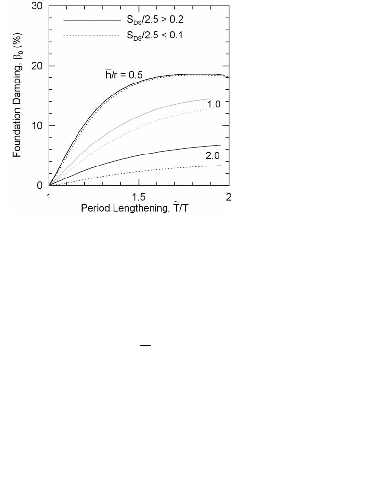
MINIMUM DESIGN LOADS
201
where
L
o
= the overall length of the side of the
foundation in the direction being analyzed
r
a
and r
m
= characteristic foundation lengths defi ned in
Eqs. 19.2-7 and 19.2-8, respectively
For intermediate values of
h
L
0
, the value of r
shall be determined by linear interpolation.
EXCEPTION: For structures supported on point-
bearing piles and in all other cases where the
foundation soil consists of a soft stratum of
reasonably uniform properties underlain by a much
stiffer, rock-like deposit with an abrupt increase in
stiffness, the factor β
o
in Eq. 19.2-9 shall be replaced
by β
o
′ if
4
1
D
vT
s
s
<
where D
s
is the total depth of the
stratum. β
o
′ shall be determined as follows:
′
=
⎛
⎝
⎜
⎞
⎠
⎟
ββ
o
s
s
o
D
vT
4
2
(19.2-12)
The value of β
˜
computed from Eq. 19.2-9, both
with or without the adjustment represented by Eq.
19.2-12, shall in no case be taken as less than β
˜
=
0.05 or greater than β
˜
= 0.20.
19.2.2 Vertical Distribution of Seismic Forces
The distribution over the height of the structure
of the reduced total seismic force (V
˜
) shall be
considered to be the same as for the structure without
interaction.
19.2.3 Other Effects
The modifi ed story shears, overturning moments,
and torsional effects about a vertical axis shall be
determined as for structures without interaction using
the reduced lateral forces.
The modifi ed defl ections (δ
˜
) shall be determined
as follows:
δδ
θ
x
ox
x
V
V
Mh
K
=+
⎡
⎣
⎢
⎤
⎦
⎥
(19.2-13)
where
M
o
= the overturning moment at the base using the
unmodifi ed seismic forces and not including the
reduction permitted in the design of the
foundation
h
x
= the height above the base to the level under
consideration
δ
x
= the defl ections of the fi xed-base structure as
determined in Section 12.8.6 using the unmodi-
fi ed seismic forces
The modifi ed story drifts and P-delta effects
shall be evaluated in accordance with the provisions
of Sections 12.8.6 and 12.8.7 using the modifi ed
story shears and defl ections determined in this
section.
19.3 MODAL ANALYSIS PROCEDURE
The following provisions are supplementary to those
presented in Section 12.9.
19.3.1 Modal Base Shears
To account for the effects of soil–structure
interaction, the base shear corresponding to the
fundamental mode of vibration (V
1
) shall be
reduced to
V
˜
1
= V
1
– ΔV
1
(19.3-1)
The reduction (ΔV
1
) shall be computed in accordance
with Eq. 19.2-2 with W
_
taken as equal to the
effective seismic weight of the fundamental period
of vibration, W
_
, and C
s
computed in accordance with
Eq. 12.8-1, except that S
DS
shall be replaced by design
spectral response acceleration of the design response
spectra at the fundamental period of the fi xed-base
structure (T
1
).
The period T
˜
shall be determined from Eq. 19.2-3
or from Eq. 19.2-5 where applicable, taking T = T
1
,
evaluating k
_
from Eq. 19.2-4 with W
_
= W
_
1
, and
computing h
_
as follows:
FIGURE 19.2-1 Foundation Damping Factor
c19.indd 201 4/14/2010 11:03:48 AM

CHAPTER 19 SOIL–STRUCTURE INTERACTION FOR SEISMIC DESIGN
202
h
wh
w
ii i
i
n
ii
i
n
=
=
=
∑
∑
ϕ
ϕ
1
1
1
1
(19.3-2)
where
w
i
= the portion of the total gravity load of the
structure at Level i
ϕ
i1
= the displacement amplitude at the i
th
level of the
structure when vibrating in its fundamental
mode
h
i
= the height above the base to Level i
The preceding designated values of W
_
, h
_
, T, and
T
˜
also shall be used to evaluate the factor α from Eq.
19.2-6 and the factor β
o
from Fig. 19.2-1. No reduc-
tion shall be made in the shear components contrib-
uted by the higher modes of vibration. The reduced
base shear (V
˜
1
) shall in no case be taken less than
0.7V
1
.
19.3.2 Other Modal Effects
The modifi ed modal seismic forces, story shears,
and overturning moments shall be determined as for
structures without interaction using the modifi ed base
shear (V
˜
1
) instead of V
1
. The modifi ed modal defl ec-
tions (δ
˜
xm
) shall be determined as follows:
δδ
θ
x
ox
x
V
V
Mh
K
1
1
1
1
1
=+
⎡
⎣
⎢
⎤
⎦
⎥
(19.3-3)
and
δ
˜
xm
= δ
xm
for m = 2, 3, . . .
(19.3-4)
where
M
o1
= the overturning base moment for the fundamen-
tal mode of the fi xed-base structure using the
unmodifi ed modal base shear V
1
δ
xm
= the modal defl ections at Level x of the fi xed-
base structure using the unmodifi ed modal
shears, V
m
The modifi ed modal drift in a story (Δ
˜
m
) shall be
computed as the difference of the defl ections (δ
˜
xm
) at
the top and bottom of the story under consideration.
19.3.3 Design Values
The design values of the modifi ed shears,
moments, defl ections, and story drifts shall be
determined as for structures without interaction by
taking the square root of the sum of the squares
(SRSS) of the respective modal contributions. In the
design of the foundation, it is permitted to reduce the
overturning moment at the foundation–soil interface
determined in this manner by 10 percent as for
structures without interaction.
The effects of torsion about a vertical axis shall be
evaluated in accordance with the provisions of Section
12.8.4, and the P-delta effects shall be evaluated in
accordance with the provisions of Section 12.8.7 using
the story shears and drifts determined in Section 19.3.2.
c19.indd 202 4/14/2010 11:03:48 AM

203
Chapter 20
SITE CLASSIFICATION PROCEDURE FOR
SEISMIC DESIGN
accelerations for liquefi able soils. Rather, a site class
is permitted to be determined in accordance with
Section 20.3 and the corresponding values of F
a
and
F
v
determined from Tables 11.4-1 and 11.4-2.
2. Peats and/or highly organic clays [H > 10 ft (3 m)]
of peat and/or highly organic clay where H =
thickness of soil.
3. Very high plasticity clays [H > 25 ft (7.6 m) with
PI > 75].
4. Very thick soft/medium stiff clays [H > 120 ft
(37 m)] with s
u
< 1,000 psf (50 kPa).
20.3.2 Soft Clay Site Class E
Where a site does not qualify under the criteria
for Site Class F and there is a total thickness of soft
clay greater than 10 ft (3 m) where a soft clay layer is
defi ned by s
u
< 500 psf (25 kPa), w ≥ 40 percent, and
PI > 20, it shall be classifi ed as Site Class E.
20.3.3 Site Classes C, D, and E
The existence of Site Class C, D, and E soils
shall be classifi ed by using one of the following three
methods with v
_
s
, N
_
, and s
_
u
computed in all cases as
specifi ed in Section 20.4:
1. v
_
s
for the top 100 ft (30 m) (v
_
s
method).
2. N
_
for the top 100 ft (30 m) (N
_
method).
3. N
_
ch
for cohesionless soil layers (PI < 20) in the
top 100 ft (30 m) and s
_
u
for cohesive soil layers
(PI > 20) in the top 100 ft (30 m) (s
_
u
method).
Where the N
_
ch
and s
_
u
criteria differ, the site shall
be assigned to the category with the softer soil.
20.3.4 Shear Wave Velocity for Site Class B
The shear wave velocity for rock, Site Class B,
shall be either measured on site or estimated by a
geotechnical engineer, engineering geologist, or
seismologist for competent rock with moderate
fracturing and weathering. Softer and more highly
fractured and weathered rock shall either be measured
on site for shear wave velocity or classifi ed as Site
Class C.
20.3.5 Shear Wave Velocity for Site Class A
The hard rock, Site Class A, category shall be
supported by shear wave velocity measurement either
20.1 SITE CLASSIFICATION
The site soil shall be classifi ed in accordance with
Table 20.3-1 and Section 20.3 based on the upper 100
ft (30 m) of the site profi le. Where site-specifi c data
are not available to a depth of 100 ft (30 m), appropri-
ate soil properties are permitted to be estimated by the
registered design professional preparing the soil
investigation report based on known geologic condi-
tions. Where the soil properties are not known in
suffi cient detail to determine the site class, Site Class
D shall be used unless the authority having jurisdic-
tion or geotechnical data determine Site Class E or F
soils are present at the site. Site Classes A and B shall
not be assigned to a site if there is more than 10 ft
(10.1 m) of soil between the rock surface and the
bottom of the spread footing or mat foundation.
20.2 SITE RESPONSE ANALYSIS FOR SITE
CLASS F SOIL
A site response analysis in accordance with Section
21.1 shall be provided for Site Class F soils, unless
the exception to Section 20.3.1 is applicable.
20.3 SITE CLASS DEFINITIONS
Site class types shall be assigned in accordance with
the defi nitions provided in Table 20.3-1 and this
section.
20.3.1 Site Class F
Where any of the following conditions is satis-
fi ed, the site shall be classifi ed as Site Class F and a
site response analysis in accordance with Section 21.1
shall be performed.
1. Soils vulnerable to potential failure or collapse
under seismic loading, such as liquefi able soils,
quick and highly sensitive clays, and collapsible
weakly cemented soils.
EXCEPTION: For structures having fundamental
periods of vibration equal to or less than 0.5 s, site
response analysis is not required to determine spectral
c20.indd 203 4/14/2010 11:03:54 AM

CHAPTER 20 SITE CLASSIFICATION PROCEDURE FOR SEISMIC DESIGN
204
on site or on profi les of the same rock type in the
same formation with an equal or greater degree of
weathering and fracturing. Where hard rock condi-
tions are known to be continuous to a depth of 100 ft
(30 m), surfi cial shear wave velocity measurements
are permitted to be extrapolated to assess v
_
s
.
20.4 DEFINITIONS OF SITE
CLASS PARAMETERS
The defi nitions presented in this section shall apply to
the upper 100 ft (30 m) of the site profi le. Profi les
containing distinct soil and rock layers shall be
subdivided into those layers designated by a number
that ranges from 1 to n at the bottom where there are
a total of n distinct layers in the upper 100 ft (30 m).
Where some of the n layers are cohesive and others
are not, k is the number of cohesive layers and m is
the number of cohesionless layers. The symbol i
refers to any one of the layers between 1 and n.
20.4.1 v
_
s
, Average Shear Wave Velocity
v
_
s
shall be determined in accordance with the
following formula:
v
d
d
v
s
i
i
n
i
si
i
n
=
=
=
∑
∑
1
1
(20.4-1)
where
d
i
= the thickness of any layer between 0 and
100 ft (30 m)
v
si
= the shear wave velocity in ft/s (m/s)
d
i
i
n
=
∑
1
= 100 ft (30 m)
20.4.2 N
_
, Average Field Standard Penetration
Resistance and N
_
ch
, Average Standard Penetration
Resistance for Cohesionless Soil Layers
N
_
and N
_
ch
shall be determined in accordance with
the following formulas:
N
d
d
N
i
i
n
i
i
i
n
=
=
=
∑
∑
1
1
(20.4-2)
where N
i
and d
i
in Eq. 20.4-2 are for cohesionless
soil, cohesive soil, and rock layers.
N
d
d
N
ch
s
i
i
i
m
=
=
∑
1
(20.4-3)
where N
i
and d
i
in Eq. 20.4-3 are for cohesionless soil
layers only and
dd
i
i
m
s
=
∑
=
1
where d
s
is the total
thickness of cohesionless soil layers in the top 100 ft
(30 m). N
i
is the standard penetration resistance
(ASTM D1586) not to exceed 100 blows/ft (305
blows/m) as directly measured in the fi eld without
corrections. Where refusal is met for a rock layer, N
i
shall be taken as 100 blows/ft (305 blows/m).
20.4.3 s
_
u
, Average Undrained Shear Strength
s
_
u
shall be determined in accordance with the
following formula:
Table 20.3-1 Site Classifi cation
Site Class v
_
s
N
_
or N
_
ch
s
_
u
A. Hard rock >5,000 ft/s NA NA
B. Rock 2,500 to 5,000 ft/s NA NA
C. Very dense soil and soft rock 1,200 to 2,500 ft/s >50 >2,000 psf
D. Stiff soil 600 to 1,200 ft/s 15 to 50 1,000 to 2,000 psf
E. Soft clay soil <600 ft/s <15 <1,000 psf
Any profi le with more than 10 ft of soil having the following characteristics:
—Plasticity index PI > 20,
—Moisture content w ≥ 40%,
—Undrained shear strength s
_
u
< 500 psf
F. Soils requiring site response analysis
in accordance with Section 21.1
See Section 20.3.1
For SI: 1 ft/s = 0.3048 m/s; 1 lb/ft
2
= 0.0479 kN/m
2
.
c20.indd 204 4/14/2010 11:03:54 AM

MINIMUM DESIGN LOADS
205
s
d
d
s
u
c
i
ui
i
k
=
=
∑
1
(20.4-4)
where
d
i
i
k
=
∑
1
= d
c
d
c
= the total thickness of cohesive soil layers in
the top 100 ft (30 m)
PI = the plasticity index as determined in accor-
dance with ASTM D4318
w = the moisture content in percent as
determined in accordance with ASTM
D2216
s
ui
= the undrained shear strength in psf (kPa), not
to exceed 5,000 psf (240 kPa) as determined
in accordance with ASTM D2166 or ASTM
D2850
c20.indd 205 4/14/2010 11:03:54 AM

c20.indd 206 4/14/2010 11:03:54 AM

207
Chapter 21
SITE-SPECIFIC GROUND MOTION PROCEDURES
FOR SEISMIC DESIGN
site coeffi cients in Section 11.4.3 consistent with the
classifi cation of the soils at the profi le base.
21.1.3 Site Response Analysis and
Computed Results
Base ground motion time histories shall be input
to the soil profi le as outcropping motions. Using
appropriate computational techniques that treat
nonlinear soil properties in a nonlinear or equivalent-
linear manner, the response of the soil profi le shall be
determined and surface ground motion time histories
shall be calculated. Ratios of 5 percent damped
response spectra of surface ground motions to input
base ground motions shall be calculated. The recom-
mended surface MCE
R
ground motion response
spectrum shall not be lower than the MCE
R
response
spectrum of the base motion multiplied by the average
surface-to-base response spectral ratios (calculated
period by period) obtained from the site response
analyses. The recommended surface ground motions
that result from the analysis shall refl ect consideration
of sensitivity of response to uncertainty in soil
properties, depth of soil model, and input motions.
21.2 RISK-TARGETED MAXIMUM
CONSIDERED EARTHQUAKE (MCE
R
)
GROUND MOTION HAZARD ANALYSIS
The requirements of Section 21.2 shall be satisfi ed
where a ground motion hazard analysis is performed
or required by Section 11.4.7. The ground motion
hazard analysis shall account for the regional tectonic
setting, geology, and seismicity, the expected recur-
rence rates and maximum magnitudes of earthquakes
on known faults and source zones, the characteristics
of ground motion attenuation, near source effects, if
any, on ground motions, and the effects of subsurface
site conditions on ground motions. The characteristics
of subsurface site conditions shall be considered either
using attenuation relations that represent regional and
local geology or in accordance with Section 21.1. The
analysis shall incorporate current seismic interpreta-
tions, including uncertainties for models and param-
eter values for seismic sources and ground motions.
The analysis shall be documented in a report.
21.1 SITE RESPONSE ANALYSIS
The requirements of Section 21.1 shall be satisfi ed
where site response analysis is performed or required
by Section 11.4.7. The analysis shall be documented
in a report.
21.1.1 Base Ground Motions
A MCE
R
response spectrum shall be developed
for bedrock, using the procedure of Sections 11.4.6 or
21.2. Unless a site-specifi c ground motion hazard
analysis described in Section 21.2 is carried out, the
MCE
R
rock response spectrum shall be developed
using the procedure of Section 11.4.6 assuming Site
Class B. If bedrock consists of Site Class A, the
spectrum shall be adjusted using the site coeffi cients
in Section 11.4.3 unless other site coeffi cients can be
justifi ed. At least fi ve recorded or simulated horizontal
ground motion acceleration time histories shall be
selected from events having magnitudes and fault
distances that are consistent with those that control
the MCE
R
ground motion. Each selected time history
shall be scaled so that its response spectrum is, on
average, approximately at the level of the MCE
R
rock
response spectrum over the period range of signifi -
cance to structural response.
21.1.2 Site Condition Modeling
A site response model based on low-strain shear
wave velocities, nonlinear or equivalent linear shear
stress–strain relationships, and unit weights shall be
developed. Low-strain shear wave velocities shall be
determined from fi eld measurements at the site or
from measurements from similar soils in the site
vicinity. Nonlinear or equivalent linear shear stress–
strain relationships and unit weights shall be selected
on the basis of laboratory tests or published relation-
ships for similar soils. The uncertainties in soil
properties shall be estimated. Where very deep soil
profi les make the development of a soil model to
bedrock impractical, the model is permitted to be
terminated where the soil stiffness is at least as great
as the values used to defi ne Site Class D in Chapter
20. In such cases, the MCE
R
response spectrum and
acceleration time histories of the base motion devel-
oped in Section 21.1.1 shall be adjusted upward using
c21.indd 207 4/14/2010 11:03:57 AM

CHAPTER 21 SITE-SPECIFIC GROUND MOTION PROCEDURES FOR SEISMIC DESIGN
208
21.2.1 Probabilistic (MCE
R
) Ground Motions
The probabilistic spectral response accelerations
shall be taken as the spectral response accelerations in
the direction of maximum horizontal response
represented by a 5 percent damped acceleration
response spectrum that is expected to achieve a 1
percent probability of collapse within a 50-year
period. For the purpose of this standard, ordinates of
the probabilistic ground motion response spectrum
shall be determined by either Method 1 of Section
21.2.1.1 or Method 2 of Section 21.2.1.2.
21.2.1.1 Method 1
At each spectral response period for which the
acceleration is computed, ordinates of the probabilistic
ground motion response spectrum shall be determined
as the product of the risk coeffi cient, C
R
, and the
spectral response acceleration from a 5 percent
damped acceleration response spectrum having a 2
percent probability of exceedance within a 50-year
period. The value of the risk coeffi cient, C
R
, shall be
determined using values of C
RS
and C
R1
from Figs.
22-3 and 22-4, respectively. At spectral response
periods less than or equal to 0.2 s, C
R
shall be taken
as equal to C
RS
. At spectral response periods greater
than or equal to 1.0 s, C
R
shall be taken as equal to
C
R1
. At response spectral periods greater than 0.2 s
and less than 1.0 s, C
R
shall be based on linear
interpolation of C
RS
and C
R1
.
21.2.1.2 Method 2
At each spectral response period for which the
acceleration is computed, ordinates of the probabilistic
ground motion response spectrum shall be determined
from iterative integration of a site-specifi c hazard
curve with a lognormal probability density function
representing the collapse fragility (i.e., probability of
collapse as a function of spectral response accelera-
tion). The ordinate of the probabilistic ground motion
response spectrum at each period shall achieve a 1
percent probability of collapse within a 50-year period
for a collapse fragility having (i) a 10 percent prob-
ability of collapse at said ordinate of the probabilistic
ground motion response spectrum and (ii) a logarith-
mic standard deviation value of 0.6.
21.2.2 Deterministic (MCE
R
) Ground Motions
The deterministic spectral response acceleration
at each period shall be calculated as an 84th-percentile
5 percent damped spectral response acceleration in the
direction of maximum horizontal response computed
at that period. The largest such acceleration calculated
for the characteristic earthquakes on all known active
faults within the region shall be used. For the purposes
of this standard, the ordinates of the deterministic
ground motion response spectrum shall not be taken as
lower than the corresponding ordinates of the response
spectrum determined in accordance with Fig. 21.2-1,
where F
a
and F
v
are determined using Tables 11.4-1
and 11.4-2, respectively, with the value of S
S
taken as
1.5 and the value of S
1
taken as 0.6.
21.2.3 Site-Specifi c MCE
R
The site-specifi c MCE
R
spectral response
acceleration at any period, S
aM
, shall be taken as
the lesser of the spectral response accelerations
from the probabilistic ground motions of Section
21.2.1 and the deterministic ground motions of
Section 21.2.2.
21.3 DESIGN RESPONSE SPECTRUM
The design spectral response acceleration at any
period shall be determined from Eq. 21.3-1:
SS
aaM
=
2
3
(21.3-1)
where S
aM
is the MCE
R
spectral response acceleration
obtained from Section 21.1 or 21.2. The design
spectral response acceleration at any period shall not
be taken as less than 80 percent of S
a
determined in
accordance with Section 11.4.5. For sites classifi ed as
Site Class F requiring site response analysis in
accordance with Section 11.4.7, the design spectral
response acceleration at any period shall not be taken
as less than 80 percent of S
a
determined for Site Class
E in accordance with Section 11.4.5.
21.4 DESIGN ACCELERATION PARAMETERS
Where the site-specifi c procedure is used to determine
the design ground motion in accordance with Section
21.3, the parameter S
DS
shall be taken as the spectral
acceleration, S
a
, obtained from the site-specifi c spectra
at a period of 0.2 s, except that it shall not be taken as
less than 90 percent of the peak spectral acceleration,
S
a
, at any period larger than 0.2 s. The parameter S
D1
shall be taken as the greater of the spectral accelera-
tion, S
a
, at a period of 1 s or two times the spectral
acceleration, S
a
, at a period of 2 s. The parameters
S
MS
and S
M1
shall be taken as 1.5 times S
DS
and S
D1
,
respectively. The values so obtained shall not be
less than 80 percent of the values determined in
c21.indd 208 4/14/2010 11:03:57 AM

MINIMUM DESIGN LOADS
209
accordance with Section 11.4.3 for S
MS
and S
M1
and
Section 11.4.4 for S
DS
and S
D1
.
For use with the Equivalent Lateral Force
Procedure, the site-specifi c spectral acceleration, S
a
,
at T shall be permitted to replace S
D1
/T in Eq. 12.8-3
and S
D1
T
L
/T
2
in Eq. 12.8-4. The parameter S
DS
calcu-
lated per this section shall be permitted to be used in
Eqs. 12.8-2, 12.8-5, 15.4-1, and 15.4-3. The mapped
value of S
1
shall be used in Eqs. 12.8-6, 15.4-2, and
15.4-4.
21.5 MAXIMUM CONSIDERED
EARTHQUAKE GEOMETRIC MEAN (MCE
G
)
PEAK GROUND ACCELERATION
21.5.1 Probabilistic MCE
G
Peak
Ground Acceleration
The probabilistic geometric mean peak ground
acceleration shall be taken as the geometric mean
peak ground acceleration with a 2 percent probability
of exceedance within a 50-year period.
21.5.2 Deterministic MCE
G
Peak
Ground Acceleration
The deterministic geometric mean peak ground
acceleration shall be calculated as the largest 84
th
-
percentile geometric mean peak ground acceleration
for characteristic earthquakes on all known active
faults within the site region. The deterministic
geometric mean peak ground acceleration shall not be
taken as lower than 0.5 F
PGA
, where F
PGA
is deter-
mined using Table 11.8-1 with the value of PGA
taken as 0.5 g.
21.5.3 Site-Specifi c MCE
G
Peak
Ground Acceleration
The site-specifi c MCE
G
peak ground acceleration,
PGA
M
, shall be taken as the lesser of the probabilistic
geometric mean peak ground acceleration of Section
21.5.1 and the deterministic geometric mean peak
ground acceleration of Section 21.5.2. The site-
specifi c MCE
G
peak ground acceleration shall not be
taken as less than 80 percent of PGA
M
determined
from Eq. 11.8-1.
FIGURE 21.2-1 Deterministic Lower Limit on MCE
R
Response Spectrum
c21.indd 209 4/14/2010 11:03:58 AM

c21.indd 210 4/14/2010 11:03:58 AM
