
Skyworks Solutions, Inc. • Phone [781] 376-3000 • Fax [781] 376-3100 • sales@skyworksinc.com • www.skyworksinc.com
Rev. 0.3 • Skyworks Proprietary Information • Products and Product Information are Subject to Change Without Notice • September 9, 2021
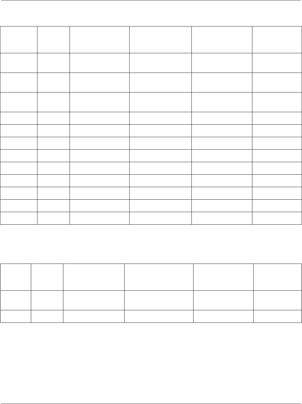
1. Introduction
This document provides general Si4822/26/27/40/44
design and AM/FM/SW antenna selection guidelines,
including schematic, BOM, and PCB layout. All users
should follow the Si4822/26/27/40/44 design guidelines
presented in “2. Si4822/26/27/40/44 Default Frequency
Band Definition and Selection” and “3.
Si48422/26/27/40/44 SSOP/SOIC Schematic and Lay-
out” and choose the appropriate antennas based on the
applications and device used as described in “4. Head-
phone Antenna for FM Receive” through “8. Whip
Antenna for SW Receiver”.
Table 1. Part Selection Guide
†Part
Number
†General
Description
Function
FM Antenna
AM Antenna
SW Antenna
FM Receiver
AM Receiver
SW Receiver
Headphone
Whip
Ferrite Loop
Air Loop
Whip
Si4822 Entry level wheel-tuned digital display
AM/FM Receiver, Mono audio
†
†
†
†
††
Si4826 Entry level wheel-tuned digital display
AM/FM/SW Receiver, Mono audio
††††††††
Si4827 Entry level wheel-tuned digital display
AM/FM/SW Receiver, wide FM/SW
band, Mono audio
††††††††
Si4840 Wheel-tuned digital display AM/FM
Receiver, Stereo audio
†† ††††
Si4844 Wheel-tuned digital display AM/FM/
SW Receiver, wide FM/SW band, Ste-
reo audio
††††††††
Si4822/26/27/40/44 ANTENNA, SCHEMATIC, LAYOUT,
AND DESIGN GUIDELINES
AN602

AN602
2 Skyworks Solutions, Inc. • Phone [781] 376-3000 • Fax [781] 376-3100 • sales@skyworksinc.com • www.skyworksinc.com
Rev. 0.3 • Skyworks Proprietary Information • Products and Product Information are Subject to Change Without Notice • September 9, 2021
2. Si4822/26/27/40/44 Default Frequency Band Definition and Selection
For Si4822/26/27/40/44, there are two methods for defining a frequency band, one is to select one of the chip
internal default bands by using the slide switch and resistor ladder. Another method is to use the host MCU
sending command to make the chip work in the desired band. Refer to application note, “AN610: Si48xx ATDD
Programming Guide”, for information on how to use the Si4822/26/27/40/44 to define a frequency band and set a
band property. This section describes how to select the default frequency band by using the slide switch and
resistors ladder.
The Si4822/40 has five defined FM bands and five defined AM bands. The Si4826/27/44 has an added 16 SW
bands. In each FM band, the parts also offer two de-emphasis selections and two LED stereo separation threshold
selections, which results in a total 41 combinations to choose from.
The Si4822/26/40/44-A supports FM band range less than 23 MHz and SW band range less than 1.15 MHz. The
Si4827-A/44-B supports wider FM/SW band range. Refer to application note, “AN610: Si48xx ATDD Programming
Guide” for details.
2.1. Si4822/26/27/40/44 Default Band Definition
For Si4822/26/27/40/44, the FM band definition is in fact a combination of frequency range, de-emphasis, and LED
stereo separation threshold. Customers should choose the band according to not only frequency range, but also
de-emphasis setting and LED stereo separation requirements. For AM and SW, simply choose the band according
to the frequency range desired.
Table 2. Band Sequence Definition
Band
Number
Band
Name
Band Frequency
Range
De-emphasis (FM)
Channel Space (AM)
Stereo LED on
Conditions
(Only for Si4840/44)
Total R to GND
(k, 1%)
Band1 FM1 87–108 MHz 75 µs Separation = 6 dB,
RSSI = 20
47
Band2 FM1 87–108 MHz 75 µs Separation = 12 dB,
RSSI = 28
57
Band3 FM1 87–108 MHz 50 µs Separation = 6dB,
RSSI = 20
67
Band4 FM1 87–108 MHz 50 µs Separation = 12 dB,
RSSI = 28
77
Band5 FM2 86.5–109 MHz 75 µs Separation = 6 dB,
RSSI = 20
87
Band6 FM2 86.5–109 MHz 75 µs Separation = 12 dB,
RSSI = 28
97
Band7 FM2 86.5–109 MHz 50 µs Separation = 6 dB,
RSSI = 20
107
Band8 FM2 86.5–109 MHz 50 µs Separation = 12 dB,
RSSI = 28
117
Band9 FM3 87.3–108.25 MHz 75 µs Separation = 6 dB,
RSSI = 20
127

AN602
Skyworks Solutions, Inc. • Phone [781] 376-3000 • Fax [781] 376-3100 • sales@skyworksinc.com • www.skyworksinc.com 3
Rev. 0.3 • Skyworks Proprietary Information • Products and Product Information are Subject to Change Without Notice • September 9, 2021
Band10 FM3 87.3–108.25 MHz 50 µs Separation = 12 dB,
RSSI = 28
137
Band11 FM3 87.3–108.25 MHz 75 µs Separation = 6 dB,
RSSI = 20
147
Band12 FM3 87.3–108.25 MHz 50 µs Separation = 12 dB,
RSSI = 28
157
Band13 FM4 76–90 MHz 75 µs Separation = 6 dB,
RSSI = 20
167
Band14 FM4 76–90 MHz 75 µs Separation = 12 dB,
RSSI = 28
177
Band15 FM4 76–90 MHz 50 µs Separation = 6 dB,
RSSI = 20
187
Band16 FM4 76–90 MHz 50 µs Separation = 12 dB,
RSSI = 28
197
Band17 FM5 64–87 MHz 75 µs Separation = 6 dB,
RSSI = 20
207
Band18 FM5 64–87 MHz 75 µs Separation = 12 dB,
RSSI = 28
217
Band19 FM5 64–87 MHz 50 µs Separation = 6 dB,
RSSI = 20
227
Band20 FM5 64–87 MHz 50 µs Separation = 12 dB,
RSSI = 28
237
Band21 AM1 520–1710 kHz 10 kHz
247
Band22 AM2 522–1620 kHz 9kHz
257
Band23 AM3 504–1665 kHz 9kHz
267
Band24 AM4 520–1730 kHz 10 kHz
277
Band25 AM5 510–1750 kHz 10 kHz
287
Band26 SW1 5.6–6.4 MHz
297
Band27 SW2 5.95–6.2 MHz
307
Band28 SW3 6.8–7.6 MHz
317
Band29 SW4 7.1–7.6 MHz
327
Band30 SW5 9.2–10 MHz
337
Table 2. Band Sequence Definition (Continued)
Band
Number
Band
Name
Band Frequency
Range
De-emphasis (FM)
Channel Space (AM)
Stereo LED on
Conditions
(Only for Si4840/44)
Total R to GND
(k, 1%)

AN602
4 Skyworks Solutions, Inc. • Phone [781] 376-3000 • Fax [781] 376-3100 • sales@skyworksinc.com • www.skyworksinc.com
Rev. 0.3 • Skyworks Proprietary Information • Products and Product Information are Subject to Change Without Notice • September 9, 2021
2.2. Default Band Selection
Refer to Figure 1 for the band selection circuits. Selecting a band is to determine the resistance value from the
band select pin to GND.
To select a specific band, you need to ensure two things:
Total value of resistance from the BAND to GND is equal to the value specified in Table 2
Total resistance from TUNE1 to GND is 500 k in 1% tolerance
Some commonly used bands and their respective selection circuits are listed below for your quick reference.
2.2.1. Typical 12-band application
Figure 1 and Table 3 illustrate the band and resistor value details for a typical 12-band application.
Band31 SW6 9.2–9.9 MHz
347
Band32 SW7 11.45–12.25 MHz
357
Band33 SW8 11.6–12.2 MHz
367
Band34 SW9 13.4–14.2 MHz
377
Band35 SW10 13.57–13.87 MHz
387
Band36 SW11 15–15.9 MHz
397
Band37 SW12 15.1–15.8 MHz
407
Band38 SW13 17.1–18 MHz
417
Band39 SW14 17.48–17.9 MHz
427
Band40 SW15 21.2–22 MHz
437
Band41 SW16 21.45–21.85 MHz
447
Table 2. Band Sequence Definition (Continued)
Band
Number
Band
Name
Band Frequency
Range
De-emphasis (FM)
Channel Space (AM)
Stereo LED on
Conditions
(Only for Si4840/44)
Total R to GND
(k, 1%)

AN602
Skyworks Solutions, Inc. • Phone [781] 376-3000 • Fax [781] 376-3100 • sales@skyworksinc.com • www.skyworksinc.com 5
Rev. 0.3 • Skyworks Proprietary Information • Products and Product Information are Subject to Change Without Notice • September 9, 2021
Figure 1. A Typical 12-Band Selection Circuit
FM1 (87MHz - 108MHz)
FM5 (64MHz - 87MHz)
AM1 (520kHz - 1710kHz)
FM4 (76MHz - 90MHz)
SW1 (5.6MHz - 6.4MHz)
SW3(6.8MHz - 7.6MHz)
SW5(9.2MHz - 10.0MHz)
SW7(11.45MHz - 12.25MHz)
SW9 (13.4MHz - 14.2MHz)
SW11 (15MHz - 15.9MHz)
SW13 (17.1MHz - 18MHz)
SW15 (21.2MHz - 22MHz)
Si4826/27/44 only
12
3
4
5
6
7
8
9
10
11
12
13
S2
R15
20k 1%
R10
20k 1%
R12
20k 1%
R11
20k 1%
R14
20k 1%
R9
20k 1%
R7
40k 1%
R8
50k 1%
R28
40k 1%
R29
120k 1%
R33
0R 1%
R35
20k 1%
R36
33k 1%
R43
30k 1%
R44
47k 1%
BAND
TUNE1
AN602
6 Skyworks Solutions, Inc. • Phone [781] 376-3000 • Fax [781] 376-3100 • sales@skyworksinc.com • www.skyworksinc.com
Rev. 0.3 • Skyworks Proprietary Information • Products and Product Information are Subject to Change Without Notice • September 9, 2021
2.2.2. Typical 2-band application for Europe
Figure 2 and Table 4 show the band and resistor value details for a typical European 2-band application.
Table 3. Typical 12-Band Selection
Band
Number
Band
Name
Band Frequency
Range
De-emphasis (FM)
Channel space (AM)
Stereo LED On
Conditions (Only
for Si4840/44)
Total R to GND
(k, 1%)
Band1 FM1 87–108 MHz 75 µs Separation = 6 dB,
RSSI = 20
47
Band13 FM4 76–90 MHz 75 µs Separation = 6 dB,
RSSI = 20
167
Band17 FM5 64–87 MHz 75 µs Separation = 6 dB,
RSSI = 20
207
Band21 AM1 520–1710 kHz 10 kHz 247
Band26 SW1 5.6–6.4 MHz 297
Band28 SW3 6.8–7.6 MHz 317
Band30 SW5 9.2–10 MHz 337
Band32 SW7 11.45–12.25 MHz 357
Band34 SW9 13.4–14.2 MHz 377
Band36 SW11 15–15.9 MHz 397
Band38 SW13 17.1–18 MHz 417
Band40 SW15 21.2–22 MHz 437
Table 4. Typical European 2-Band Selection
Band
Number
Band
Name
Band Frequency
Range
De-emphasis (FM)
Channel space (AM)
Stereo LED On
Conditions (Only
for Si4840/44)
Total R to GND
(k, 1%)
Band4 FM1 87–108 MHz 50 µs Separation = 12 dB,
RSSI = 28
77
Band22 AM2 522–1620 kHz 9kHz 257

AN602
Skyworks Solutions, Inc. • Phone [781] 376-3000 • Fax [781] 376-3100 • sales@skyworksinc.com • www.skyworksinc.com 7
Rev. 0.3 • Skyworks Proprietary Information • Products and Product Information are Subject to Change Without Notice • September 9, 2021
Figure 2. Typical 2-Band Selection Circuit for Europe
2.2.3. Typical 2-band Application for US
Figure 3 and Table 5 show the band and resistor value details for a typical 2-band application for US.
Figure 3. Typical 2-Band Selection Circuit for US
Table 5. Typical US 2-Band Selection
Band
Number
Band
Name
Band Frequency
Range
De-emphasis (FM)
Channel space (AM)
Stereo LED On
Conditions (Only for
Si4840/44)
Total R to GND
(k, 1%)
Band2 FM1 87–108 MHz 75 µs Separation = 12 dB,
RSSI = 28
57
Band21 AM1 520–1710 kHz 10 kHz 247
FM
AM
R4
180k 1%
R3
243k 1%
R5
77k 1%
12
3
S2
BAND
TUNE1
FM
AM
R4
190k 1%
R3
253k 1%
R5
57k 1%
12
3
S2
BAND
TUNE1

AN602
8 Skyworks Solutions, Inc. • Phone [781] 376-3000 • Fax [781] 376-3100 • sales@skyworksinc.com • www.skyworksinc.com
Rev. 0.3 • Skyworks Proprietary Information • Products and Product Information are Subject to Change Without Notice • September 9, 2021
3. Si48422/26/27/40/44 SSOP/SOIC Schematic and Layout
This section shows the typical schematic and layout required for optimal Si4822/26/27/40/44 performance.
Si4822/26/40/44 offer two methods to select the radio band by tuner setting and two methods to set band property
by tuner setting. Normally, there are four kinds of typical application circuits in real application, however, the Si4827
offers two methods to select the radio band by tuner setting and two methods to set band property by host MCU, so
there are two kinds of typical application circuits in real application.
3.1. Si4822/26/40/44 Application Circuit: Host MCU Select Radio Band and Set Band
Property
Figure 4 shows the applications circuits of Si4822/26/40/44 when the application is to use the host MCU to select
radio band and set band property. Normally, a push button for selecting band is connected to the host MCU. The
MCU then detects the push button’s action and sends a command to Si4822/26/40/44 to set the desired band. The
host MCU can also set the band property, such as band top frequency point and bottom frequency point, stereo
indication threshold (only for Si4840/44), de-emphasis, AM tuning spacing, etc. The two key points to ensure
Si4822/26/40/44 works properly are as follows:
1. No pull-up resistor is connected to pin 1 LNA_EN
2. Pin 5 BAND is connected to its power supply V
CC
directly
C6 & C15 are required bypass capacitors for V
DD1
/V
DD2
power supply pin 20/21. Place C6/C15 as close as
possible to the V
DD1
/V
DD2
pin 20/21 and DBYP pin 22. These recommendations are made to reduce the size of the
current loop created by the bypass cap and routing, minimize bypass cap impedance, and return all currents to the
DBYP pin.
Pin 22 is the dedicated bypass capacitor pin. Do not connect it to power supply GND on PCB.
Pin 13 and pin 14 are the GND of the chip; these pins must be well connected to the power supply GND on PCB.
Pin 9 is the RFGND of the chip; it must be well connected to the power supply GND on PCB.
C4 and/or C7 (4.7 µF) are ac coupling caps for receiver analog audio output from pin 23 and/or pin 24. The input
resistance of the amplifier, R, such as a headphone amplifier, and the capacitance, C, will set the high pass pole
given by Equation 1. Placement locations of C4 and C7 are not critical.
Equation 1. High-Pass Pole Calculation
C28 and C29 (22 pF) are crystal loading caps required only when using the internal oscillator feature. Refer to the
crystal data sheet for the proper load capacitance and be certain to account for parasitic capacitance. Place caps
C28 and C29 such that they share a common GND connection and the current loop area of the crystal and loading
caps is minimized.
Y1 (32.768 kHz) is an optional crystal required only when using the internal oscillator feature. Place the crystal Y1
as close to XTALO pin 18 and XTALI pin 19 as possible to minimize current loops. If applying an external clock
(32.768 kHz) to XTALI, leave XTALO floating.
Do not route digital signals or reference clock traces near pin 6 and 7. Do not route Pin 6 & 7. These pins must be
left floating to guarantee proper operation.
Pin 2, 15, 16, 17 are the required communication pins with host MCU. A 100 k pull-up resistor R6 and 0.1 µF
bypass cap C19 are recommended for the pin 15 RST. Pull-up resistor R3 of 10 k is necessary for pin 16 SDIO.
VR1 (100 k / 10%), R27, C1, C13 constitute the tuning circuit. 100kat 10% tolerance is recommended for VR1.
Q1(2SC9018), together with its peripherals B6, C30,31,33,36, R31,32,34,41, is the LNA circuit for all SW bands.
The LNA is switched off by LNA_EN signal in AM and FM mode controlled by Si4826/44.
For Si4822/26, do not route pin 23. This pin must be left floating to guarantee proper operation.
f
c
1
2RC
----------------
=

AN602
Skyworks Solutions, Inc. • Phone [781] 376-3000 • Fax [781] 376-3100 • sales@skyworksinc.com • www.skyworksinc.com 9
Rev. 0.3 • Skyworks Proprietary Information • Products and Product Information are Subject to Change Without Notice • September 9, 2021
Figure 4. Si4822/26/40/44 Applications Circuit: MCU Select Band and Set Band Property
Si4822/26/40/44
Si4826/44 only
FM/SW
Optional
To host MCU
To host MCU
(For Si4822/26, pin23 is NC)
(For Si4822/26, pin24 is AOUT)
L2
270nH
C19
0.1u
C15
4.7u
VR1
100k 10%
C6
0.1u
R6
100k
C5
0.47u
Q1
2SC9018
R31
1k
R32
10R
C30
33n
C33
10p
R41
120k
C31
33n
B6
2.5k/100M
C36
0.47u
ANT1
MW ferrite antenna
R34
100k
C34
33p
1
LNA_EN
2
IRQ
3
TUNE1
4
TUNE2
5
BAND
6
NC
7
NC
8
FMI
9
RFGND
10
NC
11
NC
12
AMI
13
GND
14
GND
15
RST
16
SDIO
17
SCLK
18
XTA LO
19
XTA LI
20
VDD1
21
VDD2
22
DBYP
23
ROUT/NC
24
LOUT/A OUT
U1
C1
0.1u
R27
100R
C13
47u
C4
4.7u
C7
4.7u
Y1
32.768KHz
C28
22p
C29
22p
R3
10k
ANT2
LNA_EN[1]
LNA_EN
[1]
TUNE1
RESET
VCC
VCC
VCC
IRQ
SCLK
SDIO
VCC
VCCVCC
LOUT
ROUT

AN602
10 Skyworks Solutions, Inc. • Phone [781] 376-3000 • Fax [781] 376-3100 • sales@skyworksinc.com • www.skyworksinc.com
Rev. 0.3 • Skyworks Proprietary Information • Products and Product Information are Subject to Change Without Notice • September 9, 2021
3.2. Si4822/26/40/44 Application Circuits: Host MCU Select Default Band and Use Default
Band Property
Figure 5 shows Si4822/26/40/44 application circuits that enable the host MCU to select default bands. In this
application, the host MCU sends commands to Si4822/26/40/44 to select the desired default band. However, the
MCU cannot define those band properties already fixed in the default band definition, as stated in “2.1.
Si4822/26/27/40/44 Default Band Definition”. The host MCU can only define the band properties which are not
fixed in the default band definition, such as softmute property, etc. For more details, refer to “AN610: Si48xx ATDD
Programming Guide”. The two key points to ensure Si4822/26/40/44 works properly are as follows:
1. Add pull-up resistor R42 of 10k to pin 1 LNA_EN.
2. Ensure pin 5 BAND is connected to its power supply V
CC
directly.
Figure 5. SiSi4822/26/40/44 Applications Circuit: MCU Select Default Band and Use Default Band
Property
Si4822/26/40/44
Si4826/44 only
FM/SW
To host MCU
Optional
To host MCU
(For Si4822/26, pin23 is NC)
(For Si4822/26, pin24 is AOUT)
L2
270nH
C19
0.1u
C15
4.7u
VR1
100k 10%
C6
0.1u
R6
100k
C5
0.47u
Q1
2SC9018
R31
1k
R32
10R
C30
33n
C33
10p
R41
120k
C31
33n
B6
2.5k/100M
C36
0.47u
ANT1
MW ferrite antenna
R34
100k
C34
33p
1
LNA_EN
2
IRQ
3
TUNE1
4
TUNE2
5
BAND
6
NC
7
NC
8
FMI
9
RFGND
10
NC
11
NC
12
AMI
13
GND
14
GND
15
RST
16
SDIO
17
SCLK
18
XTA LO
19
XTA LI
20
VDD1
21
VDD2
22
DBYP
23
ROUT/NC
24
LOUT/A OUT
U1
C1
0.1u
R27
100R
C13
47u
C4
4.7u
C7
4.7u
Y1
32.768KHz
C28
22p
C29
22p
R3
10k
R42
10k
ANT2
LNA_EN[1]
LNA_EN
[1]
TUNE1
RESET
VCC
VCC
VCC
IRQ
SCLK
SDIO
VCC
VCCVCC
LOUT
ROUT
VCC

AN602
Skyworks Solutions, Inc. • Phone [781] 376-3000 • Fax [781] 376-3100 • sales@skyworksinc.com • www.skyworksinc.com 11
Rev. 0.3 • Skyworks Proprietary Information • Products and Product Information are Subject to Change Without Notice • September 9, 2021
3.3. Si4822/26/40/44 Application Circuits: Slide Switch Select Band and MCU Re-define
Band Property
Figure 7 illustrates an Si4822/26/40/44 application circuit which uses a slide switch for band selection and enables
the host MCU to re-define the band property. For the band selection method using slide switch and resistors ladder,
refer to "2.2. Default Band Selection" on page 4. In this application, the user can select any default band and the
MCU will re-define the band’s property according to the design requirement. The MCU can only re-define the
selected band’s property, it cannot change an FM band to an AM or SW band, and vice versa. The two key points
to ensure the Si4822/26/40/44 works properly are as follows:
1. No pull-up resistor is connected to pin 1 LNA_EN.
2. Pin 5 BAND is connected to slide switch.
Figure 6. Si4822/26/40/44 Applications Circuit: Slide Switch Select Band and
MCU Re-define Band Property
FM1 (87MHz - 108MHz)
FM5 (64MHz - 87MHz)
AM1 (520kHz - 1710kHz)
Si4822/26/40/44
FM4 (76MHz - 90MHz)
SW1 (5.6MHz - 6.4MHz)
SW3(6.8MHz - 7.6MHz)
SW5(9.2MHz - 10.0MHz)
SW7(11.45MHz - 12.25MHz)
SW9 (13.4MHz - 14.2MHz)
SW11 (15MHz - 15.9MHz)
SW13 (17.1MHz - 18MHz)
SW15 (21.2MHz - 22MHz)
Si4826/44 only
Si4826/44 only
FM/SW
Optional
To host MCU
To host MCU
(For Si4822/26, pin23 is NC)
(For Si4822/26, pin24 is AOUT)
12
3
4
5
6
7
8
9
10
11
12
13
S2
R15
20k 1%
R10
20k 1%
R12
20k 1%
R11
20k 1%
R14
20k 1%
R9
20k 1%
R7
20k 1%
R8
50k 1%
R28
40k 1%
R29
120k 1%
L2
270nH
C19
0.1u
C15
4.7u
VR1
100k 10%
C6
0.1u
R6
100k
C5
0.47u
Q1
2SC9018
R31
1k
R32
10R
C30
33n
C33
10p
R41
120k
C31
33n
B6
2.5k/100M
C36
0.47u
ANT1
MW ferrite antenna
R34
100k
C34
33p
1
LNA_EN
2
IRQ
3
TUNE1
4
TUNE2
5
BAND
6
NC
7
NC
8
FMI
9
RFGND
10
NC
11
NC
12
AMI
13
GND
14
GND
15
RST
16
SDIO
17
SCLK
18
XTA LO
19
XTA LI
20
VDD1
21
VDD2
22
DBYP
23
ROUT/NC
24
LOUT/A OUT
U1
C1
0.1u
R27
100R
R33
20k 1%
R35
20k 1%
R36
33k 1%
C13
47u
R43
30k 1%
R44
47k 1%
C4
4.7u
C7
4.7u
Y1
32.768KHz
C28
22p
C29
22p
R3
10k
ANT2
BAND
[1]
LNA_EN[1]
LNA_EN
[1]
BAND
[1]
TUNE1
[1]
TUNE1
[1]
RESET
VCC
VCC
VCC
IRQ
SCLK
SDIO
VCC
LOUT
ROUT

AN602
12 Skyworks Solutions, Inc. • Phone [781] 376-3000 • Fax [781] 376-3100 • sales@skyworksinc.com • www.skyworksinc.com
Rev. 0.3 • Skyworks Proprietary Information • Products and Product Information are Subject to Change Without Notice • September 9, 2021
3.4. Si4822/26/40/44 Application Circuits: Slide Switch Select Band and
Use Default Band Property
Figure 7shows an application circuit that uses a slide switch for band selection. In this example, the host MCU
cannot change those band properties already fixed in the default band definition, as stated in section 2.1, it can
only define the band properties which are not fixed in the default band definition, such as softmute property, etc.
For more details, refer to “AN610: Si48xx ATDD Programming Guide”. The two key points to ensure
Si4822/26/40/44 works properly are as follows:
1. Add pull-up resistor R42 of 10 k to pin 1 LNA_EN.
2. Pin 5 BAND is connected to slide switch.
Figure 7. Si4822/26/40/44 Applications Circuit: Slide Switch Select Band and Use Default Band
Property
FM1 (87MHz - 108MHz)
FM5 (64MHz - 87MHz)
AM1 (520kHz - 1710kHz)
Si4822/26/40/44
FM4(76MHz - 90MHz)
SW1 (5.6MHz - 6.4MHz)
SW3(6.8MHz - 7.6MHz)
SW5(9.2MHz - 10.0MHz)
SW7(11.45MHz - 12.25MHz)
SW9 (13.4MHz - 14.2MHz)
SW11 (15MHz - 15.9MHz)
SW13 (17.1MHz - 18MHz)
SW15 (21.2MHz - 22MHz)
Si4826/44 only
Si4826/44 only
FM/SW
To host MCU
Optional
To host MCU
(For Si4822/26, pin23 is NC)
(For Si4822/26, pin24 is AOUT)
12
3
4
5
6
7
8
9
10
11
12
13
S2
R15
20k 1%
R10
20k 1%
R12
20k 1%
R11
20k 1%
R14
20k 1%
R9
20k 1%
R7
20k 1%
R8
50k 1%
R28
40k 1%
R29
120k 1%
L2
270nH
C19
0.1u
C15
4.7u
VR1
100k 10%
C6
0.1u
R6
100k
C5
0.47u
Q1
2SC9018
R31
1k
R32
10R
C30
33n
C33
10p
R41
120k
C31
33n
B6
2.5k/100M
C36
0.47u
ANT1
MW ferrite antenna
R34
100k
C34
33p
1
LNA_EN
2
IRQ
3
TUNE1
4
TUNE2
5
BAND
6
NC
7
NC
8
FMI
9
RFGND
10
NC
11
NC
12
AMI
13
GND
14
GND
15
RST
16
SDIO
17
SCLK
18
XTA LO
19
XTA LI
20
VDD1
21
VDD2
22
DBYP
23
ROUT/NC
24
LOUT/A OUT
U1
C1
0.1u
R27
100R
R33
20k 1%
R35
20k 1%
R36
33k 1%
C13
47u
R43
30k 1%
R44
47k 1%
C4
4.7u
C7
4.7u
Y1
32.768KHz
C28
22p
C29
22p
R3
10k
R42
10k
ANT2
BAND
[1]
LNA_EN[1]
LNA_EN
[1]
BAND
[1]
TUNE1
[1]
TUNE1
[1]
RESET
VCC
VCC
VCC
IRQ
SCLK
SDIO
VCC
LOUT
ROUT
VCC

AN602
Skyworks Solutions, Inc. • Phone [781] 376-3000 • Fax [781] 376-3100 • sales@skyworksinc.com • www.skyworksinc.com 13
Rev. 0.3 • Skyworks Proprietary Information • Products and Product Information are Subject to Change Without Notice • September 9, 2021
3.5. Si4827 Application Circuit: Host MCU to Select Radio Band
Figure 8 shows the Si4827 application circuit that the host MCU uses to select radio band. In this application, the
host MCU sends commands to the Si4827 to select the desired band. Setting the band property by MCU or using
the tuner default band property is determined by host MCU.
Setting the band property by MCU means that the host MCU can set the band property, such as band top
frequency point and bottom frequency point, de-emphasis, AM tuning spacing, etc.
Using the tuner default band property means that the MCU cannot define those band properties already fixed in the
default band definition, as stated in section “2.1. Si4822/26/27/40/44 Default Band Definition”. The host MCU can
only define the band properties which are not fixed in the default band definition, such as softmute property, etc.
For more details, refer to application note, "AN610: Si48xx ATDD Programming Guide".
The key point to ensure the Si4827 works properly is that pin 4 BAND is connected to it's power supply V
CC
directly.
Figure 8. Si4827 Application Circuit: Host MCU Select Band

AN602
14 Skyworks Solutions, Inc. • Phone [781] 376-3000 • Fax [781] 376-3100 • sales@skyworksinc.com • www.skyworksinc.com
Rev. 0.3 • Skyworks Proprietary Information • Products and Product Information are Subject to Change Without Notice • September 9, 2021
3.6. Si4827 Application Circuit: Slide Switch Select Band
Figure 9 shows the Si4827 application circuit in which a slide switch is used for band selection. For the band
selection method using slide switch and resistors ladder, refer to section.“2.2. Default Band Selection”. Setting the
band property by MCU or using the tuner default band property is determined by host MCU.
When setting the band property by MCU, the user can select any default band and the MCU will re-define the
band's property according to the design requirement. The MCU can only re-define the selected band's property, it
cannot change an FM band to an AM or SW band, and vice versa.
When using the tuner default band property, the host MCU cannot change those band properties already fixed in
the default band definition, as stated in section “2.1. Si4822/26/27/40/44 Default Band Definition”, it can only define
the band properties which are not fixed in the default band definition, such as softmute property, etc. For more
details, refer to application note, "AN610: Si48xx ATDD Programming Guide".
The key point to ensure the Si4827 works properly is that pin 4 BAND is connected to slide switch.
Figure 9. Si4827 Application Circuit: Slide Switch Select Band

AN602
Skyworks Solutions, Inc. • Phone [781] 376-3000 • Fax [781] 376-3100 • sales@skyworksinc.com • www.skyworksinc.com 15
Rev. 0.3 • Skyworks Proprietary Information • Products and Product Information are Subject to Change Without Notice • September 9, 2021
3.7. Si4822/26/27/40/44 Bill of Materials
Table 6. Si4822/26/40/44 Applications Circuit: Host MCU Select Band and Set Band Property
Component(s) Value/Description Supplier
C1,C6,C19 Supply bypass capacitor, 0.1 µF, ±20%, Z5U/X7R Murata
C5 Capacitor, 0.47 µF, ±20%, Z5U/X7R Murata
C34 RF coupling capacitors, 33 pF, ±5%, COG Murata
C4,C7,C15 Capacitor 4.7 µF, ±20%, Z5U/X7R Murata
C13 Capacitor 47 µF, ±20%, Z5U/X7R Murata
R27 Resistor, 100 , ±5% Venkel
R6 Resistor, 100 k, ±5% Venkel
R3 Resistor, 10 k, ±5% Venkel
U1 Si4822/26/40/44 AM/FM/SW Analog Tune Digital Display Radio
Tuner
Skyworks
L2 Inductor 270 nH Murata
ANT1 MW ferrite antenna 220 µH. Jiaxin Electronics
ANT2 Whip antenna Various
VR1 Variable resistor (POT), 100 k, ±10% Changtaier
Si4826/44 Only
C36 Capacitor, 0.47 µF, ±20%, Z5U/X7R Murata
C33 Capacitor, 10 pF, ±5%, COG Murata
C30-31 Capacitor, 33 nF, ±5%, COG Murata
B6 Ferrite bead,2.5 k/100 MHz. Murata
Q1 RF transistor, 2SC9018. ETC
R34 Resistor, 100 k, ±5% Venkel
R41 Resistor, 120 k, ±5% Venkel
R32 Resistor, 10 , ±5% Venkel
R31 Resistor, 1 k, ±5% Venkel
Optional
C28, C29 Crystal load capacitors, 22 pF, ±5%, COG (Optional: for crystal
oscillator option)
Murata
Y1 32.768 kHz crystal (Optional: for crystal oscillator option) Epson

AN602
16 Skyworks Solutions, Inc. • Phone [781] 376-3000 • Fax [781] 376-3100 • sales@skyworksinc.com • www.skyworksinc.com
Rev. 0.3 • Skyworks Proprietary Information • Products and Product Information are Subject to Change Without Notice • September 9, 2021
Table 7. Si4822/26/40/44 Applications Circuit: MCU Select Default Band and Use Default Band
Property
Component(s) Value/Description Supplier
C1,C6,C19 Supply bypass capacitor, 0.1 µF, ±20%, Z5U/X7R Murata
C5 Capacitor, 0.47 µF, ±20%, Z5U/X7R Murata
C34 RF coupling capacitors, 33 pF, ±5%, COG Murata
C4,C7,C15 Capacitor 4.7 µF, ±20%, Z5U/X7R Murata
C13 Capacitor 47 µF, ±20%, Z5U/X7R Murata
R27 Resistor, 100 , ±5% Venkel
R6 Resistor, 100 k, ±5% Venkel
R3, R42 Resistor, 10 k, ±5% Venkel
U1 Si4822/26/40/44 AM/FM/SW Analog Tune Digital Display Radio
Tuner
Skyworks
L2 Inductor 270 nH Murata
ANT1 MW ferrite antenna 220 µH. Jiaxin Electronics
ANT2 Whip antenna Various
VR1 Variable resistor (POT), 100 k, ±10% Changtaier
Si4826/44 Only
C36 Capacitor, 0.47 µF, ±20%, Z5U/X7R Murata
C33 Capacitor, 10 pF, ±5%, COG Murata
C30-31 Capacitor, 33 nF, ±5%, COG Murata
B6 Ferrite bead, 2.5 k/100 MHz Murata
Q1 RF transistor, 2SC9018. ETC
R34 Resistor, 100 k, ±5% Venkel
R41 Resistor, 120 k, ±5% Venkel
R32 Resistor, 10 , ±5% Venkel
R31 Resistor, 1 k, ±5% Venkel
Optional
C28, C29 Crystal load capacitors, 22 pF, ±5%, COG (Optional:
for crystal oscillator option)
Murata
Y1 32.768 kHz crystal (Optional: for crystal oscillator option) Epson

AN602
Skyworks Solutions, Inc. • Phone [781] 376-3000 • Fax [781] 376-3100 • sales@skyworksinc.com • www.skyworksinc.com 17
Rev. 0.3 • Skyworks Proprietary Information • Products and Product Information are Subject to Change Without Notice • September 9, 2021
Table 8. Si4822/26/40/44 Application Circuits: Slide Switch Select Band and MCU Re-define Band
Property
Component(s) Value/Description Supplier
C1,C6,C19 Supply bypass capacitor, 0.1 µF, ±20%, Z5U/X7R Murata
C5 Capacitor, 0.47 µF, ±20%, Z5U/X7R Murata
C34 RF coupling capacitors, 33 pF, ±5%, COG Murata
C4,C7,C15 Capacitor 4.7 µF, ±20%, Z5U/X7R Murata
C13 Capacitor 47 µF, ±20%, Z5U/X7R Murata
R27 Resistor, 100 , ±5% Venkel
R6 Resistor, 100 k, ±5% Venkel
R3 Resistor, 10 k, ±5% Venkel
R7,R33 Band switching resistor, 20 k, ±1% Venkel
R28 Band switching resistor, 40 k, ±1% Venkel
R29 Band switching resistor, 120 k, ±1% Venkel
R44 Band switching resistor, 47 k, ±1% Venkel
R43 Band switching resistor, 30 k, ±1% Venkel
R36 Band switching resistor, 33 k, ±1% Venkel
U1 Si4822/26/40/44 AM/FM/SW Analog Tune Digital Display Radio
Tuner
Skyworks
L2 Inductor 270 nH Murata
ANT1 MW ferrite antenna 220 µH Jiaxin Electronics
ANT2 Whip antenna Various
VR1 Variable resistor (POT), 100 k, ±10% Changtaier
S2 Slide switch Shengda
Si4826/44 Only
C36
Capacitor, 0.47 µF, ±20%, Z5U/X7R
Murata
C33
Capacitor, 10 pF, ±5%, COG
Murata
C30-31
Capacitor, 33 nF, ±5%, COG
Murata
B6
Ferrite bead, 2.5 k/100 MHz
Murata
Q1
RF transistor, 2SC9018.
ETC
R34
Resistor, 100 k, ±5%
Venkel
R41
Resistor, 120 k, ±5%
Venkel
R32
Resistor, 10 , ±5%
Venkel

AN602
18 Skyworks Solutions, Inc. • Phone [781] 376-3000 • Fax [781] 376-3100 • sales@skyworksinc.com • www.skyworksinc.com
Rev. 0.3 • Skyworks Proprietary Information • Products and Product Information are Subject to Change Without Notice • September 9, 2021
R31
Resistor, 1 k, ±5%
Venkel
R9-12, R14-15,
R35
Band switching resistor, 20 k, ±1%
Venkel
R8
Band switching resistor, 50 k, ±1%
Venkel
Optional
C28, C29 Crystal load capacitor, 22 pF, ±5%, COG (Optional: for crystal
oscillator option)
Murata
Y1 32.768 kHz crystal (Optional: for crystal oscillator option) Epson
Table 9. Si4822/26/40/44 Application Circuits: Slide Switch Select Band and Use Default Band
Property
Component(s) Value/Description Supplier
C1,C6,C19
Supply bypass capacitor, 0.1 µF, ±20%, Z5U/X7R
Murata
C5
Capacitor, 0.47 µF, ±20%, Z5U/X7R
Murata
C34
RF coupling capacitors, 33 pF, ±5%, COG
Murata
C4,C7,C15
Capacitor 4.7 µF, ±20%, Z5U/X7R
Murata
C13
Capacitor 47 µF, ±20%, Z5U/X7R
Murata
R27
Resistor, 100 , ±5%
Venkel
R6
Resistor, 100 k, ±5%
Venkel
R3, R42
Resistor, 10 k, ±5%
Venkel
R7,R33
Band switching resistor, 20 k, ±1%
Venkel
R28
Band switching resistor, 40 k, ±1%
Venkel
R29
Band switching resistor, 120 k, ±1%
Venkel
R44
Band switching resistor, 47 k, ±1%
Venkel
R43
Band switching resistor, 30 k, ±1%
Venkel
R36
Band switching resistor, 33 k, ±1%
Venkel
U1
Si4822/26/40/44 AM/FM/SW Analog Tune Digital Display Radio
Tuner
Skyworks
L2
Inductor 270 nH
Murata
ANT1
MW ferrite antenna 220 µH
Jiaxin Electronics
ANT2
Whip antenna
Various
Table 8. Si4822/26/40/44 Application Circuits: Slide Switch Select Band and MCU Re-define Band
Property (Continued)

AN602
Skyworks Solutions, Inc. • Phone [781] 376-3000 • Fax [781] 376-3100 • sales@skyworksinc.com • www.skyworksinc.com 19
Rev. 0.3 • Skyworks Proprietary Information • Products and Product Information are Subject to Change Without Notice • September 9, 2021
VR1
Variable resistor (POT), 100 k, ±10%
Changtaier
S2
Slide switch
Shengda
Si4826/44 Only
C36
Capacitor, 0.47 µF, ±20%, Z5U/X7R
Murata
C33
Capacitor, 10 pF, ±5%, COG
Murata
C30-31
Capacitor, 33 nF, ±5%, COG
Murata
B6
Ferrite bead, 2.5 k/100 MHz
Murata
Q1
RF transistor, 2SC9018
ETC
R34
Resistor, 100 k, ±5%
Venkel
R41
Resistor, 120 k, ±5%
Venkel
R32
Resistor, 10 , ±5%
Venkel
R31
Resistor, 1 k, ±5%
Venkel
R9-12, R14-15,
R35
Band switching resistor, 20 k, ±1%
Venkel
R8
Band switching resistor, 50 k, ±1%
Venkel
Optional
C28, C29 Crystal load capacitor, 22 pF, ±5%, COG (Optional: for crystal
oscillator option)
Murata
Y1 32.768 kHz crystal (Optional: for crystal oscillator option) Epson
Table 9. Si4822/26/40/44 Application Circuits: Slide Switch Select Band and Use Default Band
Property (Continued)
Component(s) Value/Description Supplier

AN602
20 Skyworks Solutions, Inc. • Phone [781] 376-3000 • Fax [781] 376-3100 • sales@skyworksinc.com • www.skyworksinc.com
Rev. 0.3 • Skyworks Proprietary Information • Products and Product Information are Subject to Change Without Notice • September 9, 2021
Table 10. Si4827 Application Circuit: MCU Select Band
Component(s) Value/Description Supplier
C1,C6,C19 Supply bypass capacitor, 0.1 µF, ±20%, Z5U/X7R Murata
C5,C36 Capacitor, 0.47 µF, ±20%, Z5U/X7R Murata
C34 RF coupling capacitors, 33 pF, ±5%, COG Murata
C7,C15 Capacitor 4.7 µF, ±20%, Z5U/X7R Murata
C13 Capacitor 47 µF, ±20%, Z5U/X7R Murata
R27 Resistor, 100 , ±5% Venkel
R6 R34 Resistor, 100 k, ±5% Venkel
R3 Resistor, 10 k, ±5% Venkel
U1 Si4827-A AM/FM/SW Analog Tune Digital Display Radio Tuner Skyworks
L2 Inductor 270 nH Murata
ANT1 MW ferrite antenna 220 µH Jiaxin Electronics
ANT2 Whip antenna Various
VR1 Variable resistor (POT), 100 k, ±10% Changtaier
C33 Capacitor, 10 pF, ±5%, COG Murata
C30-31 Capacitor, 33 nF, ±5%, COG Murata
B6 Ferrite bead,2.5k/100 MHz Murata
Q1 RF transistor, 2SC9018 ETC
R41 Resistor, 120 k, ±5% Venkel
R32 Resistor, 10 , ±5% Venkel
R31 Resistor, 1 k, ±5% Venkel
Optional
C28, C29 Crystal load capacitors, 22 pF, ±5%, COG (Optional: for crystal
oscillator option)
Murata
Y1 32.768 kHz crystal (Optional: for crystal oscillator option) Epson

AN602
Skyworks Solutions, Inc. • Phone [781] 376-3000 • Fax [781] 376-3100 • sales@skyworksinc.com • www.skyworksinc.com 21
Rev. 0.3 • Skyworks Proprietary Information • Products and Product Information are Subject to Change Without Notice • September 9, 2021
Table 11. Si4827 Application Circuit: Slide Switch Select Band
Component(s) Value/Description Supplier
C1,C6,C19 Supply bypass capacitor, 0.1 µF, ±20%, Z5U/X7R Murata
C5,C36 Capacitor, 0.47 µF, ±20%, Z5U/X7R Murata
C34 RF coupling capacitors, 33 pF, ±5%, COG Murata
C7,C15 Capacitor 4.7 µF, ±20%, Z5U/X7R Murata
C13 Capacitor 47 µF, ±20%, Z5U/X7R Murata
R27 Resistor, 100 , ±5% Venkel
R6 R34 Resistor, 100 k, ±5% Venkel
R3 Resistor, 10 k, ±5% Venkel
U1 Si4827-A AM/FM/SW Analog Tune Digital Display Radio Tuner Skyworks
L2 Inductor 270 nH Murata
ANT1 MW ferrite antenna 220 µH Jiaxin Electronics
ANT2 Whip antenna Various
VR1 Variable resistor (POT), 100 k
, ±10% Changtaier
C33 Capacitor, 10 pF, ±5%, COG Murata
C30-31 Capacitor, 33 nF, ±5%, COG Murata
B6 Ferrite bead, 2.5 k/100 MHz Murata
Q1 RF transistor, 2SC9018 ETC
R41 Resistor, 120 k
, ±5% Venkel
R32 Resistor, 10
, ±5% Venkel
R31 Resistor, 1 k
, ±5% Venkel
Optional
C28, C29 Crystal load capacitors, 22 pF, ±5%, COG (Optional: for crystal
oscillator option)
Murata
Y1 32.768 kHz crystal (Optional: for crystal oscillator option) Epson

AN602
22 Skyworks Solutions, Inc. • Phone [781] 376-3000 • Fax [781] 376-3100 • sales@skyworksinc.com • www.skyworksinc.com
Rev. 0.3 • Skyworks Proprietary Information • Products and Product Information are Subject to Change Without Notice • September 9, 2021
3.8. Si4822/26/27/40/44 PCB Layout Guidelines
1-layer PCB is used for Si4822/26/27/40/44
GND routed by large plane
Power routed with traces
0402 component size or larger
10 mil traces width
20 mil trace spacing
15 mil component spacing
Keep the AM ferrite loop at least 5 cm away from the tuner chip (recommended)
Keep the AM ferrite loop antenna away from the MCU, audio amp, and other circuits which have AM
interference
Place V
DD1
/V
DD2
bypass capacitor C6, C15 as close as possible to the supply (pin20/pin 21) and DBYP (pin 22).
Do not connect the DBYP (pin 22) to the board GND.
Place the crystal as close to XTALO (pin18) and XTALI (pin19) as possible, and make the loop area of XTALO
trace and XTALI trace as small as possible.
Route all GND (including RFGND) pins to the GND plane underneath the chip. Try to create a large GND plane
underneath and around the chip.
Do not route Pin 6 and 7. These pins must be left floating to guarantee proper operation.
Keep the Tune1 and Tune2 traces away from pin 6 and pin 7, route Tune1 and Tune2 traces in parallel and the
same way.
Place C1, C13 as close to pin3 TUNE1 as possible.
For Si4822/26, do not route pin 23, leave it floating to guarantee proper operation.
Try to refer to the Si4840/44 PCB Layout example as much as possible when doing Si4822/26/27 PCB layout.
Figure 10. Si4840/44 PCB Layout Example

AN602
Skyworks Solutions, Inc. • Phone [781] 376-3000 • Fax [781] 376-3100 • sales@skyworksinc.com • www.skyworksinc.com 23
Rev. 0.3 • Skyworks Proprietary Information • Products and Product Information are Subject to Change Without Notice • September 9, 2021
4. Headphone Antenna for FM Receive
The Si4822/26/27/40/44 FM Receiver component supports a headphone antenna interface through the FMI pin. A
headphone antenna with a length between 1.1 and 1.45 m suits the FM application very well because it is
approximately half the FM wavelength (FM wavelength is ~3 m).
4.1. Headphone Antenna Design
A typical headphone cable will contain three or more conductors. The left and right audio channels are driven by a
headphone amplifier onto left and right audio conductors and the common audio conductor is used for the audio
return path and FM antenna. Additional conductors may be used for microphone audio, switching, or other
functions, and in some applications the FM antenna will be a separate conductor within the cable. A representation
of a typical application is shown in Figure 11.
Figure 11. Typical Headphone Antenna Application

AN602
24 Skyworks Solutions, Inc. • Phone [781] 376-3000 • Fax [781] 376-3100 • sales@skyworksinc.com • www.skyworksinc.com
Rev. 0.3 • Skyworks Proprietary Information • Products and Product Information are Subject to Change Without Notice • September 9, 2021
4.2. Headphone Antenna Schematic
Figure 12. Headphone Antenna Schematic
The headphone antenna implementation requires components L
MATCH
, C4, F1, and F2 for a minimal
implementation. The ESD protection diodes and headphone amplifier components are system components that will
be required for proper implementation of any tuner.
Inductor L
MATCH
is selected to maximize the voltage gain across the FM band. L
MATCH
should be selected with a Q
of 15 or greater at 100 MHz and minimal dc resistance.
AC-coupling capacitor C4 is used to remove a dc offset on the FMI input. This capacitor must be chosen to be large
enough to cause negligible loss with an LNA input capacitance of 4 to 6 pF. The recommended value is 100 pF to
1nF.
Ferrite beads F1 and F2 provide a low-impedance audio path and high-impedance RF path between the
headphone amplifier and the headphone. Ferrite beads should be placed on each antenna conductor connected to
nodes other than the FMIP, such as left and right audio, microphone audio, switching, etc. In the example shown in
Figure 12, these nodes are the left and right audio conductors. Ferrite beads should be 2.5 k or greater at
100 MHz, such as the Murata BLM18BD252SN1. High resistance at 100 MHz is desirable to maximize R
SHUNT
and, therefore, R
P
. Refer to “AN383: Si47xxAntenna, Schematic, and Layout Guidelines”, Appendix A, for a
complete description of R
SHUNT
, R
P
, etc.
ESD diodes D1, D2, and D3 are recommended if design requirements exceed the ESD rating of the headphone
amplifier and the Si4822/26/40/44. Diodes should be chosen with no more than 1 pF parasitic capacitance, such as
the California Micro Devices CM1210. Diode capacitance should be minimized to minimize C
SHUNT
and, therefore,
C
P
. If D1 and D2 must be chosen with a capacitance greater than 1 pF, they should be placed between the ferrite
beads F1 and F2 and the headphone amplifier to minimize C
SHUNT
. This placement will, however, reduce the
effectiveness of the ESD protection devices. Diode D3 may not be relocated and must therefore have a
capacitance less than 1 pF. Note that each diode package contains two devices to protect against positive and
negative polarity ESD events.
C9 and C10 are 125 µF ac coupling capacitors required when the audio amplifier does not have a common mode
output voltage and the audio output is swinging above and below ground.
Optional bleed resistors R5 and R6 may be desirable to discharge the ac-coupling capacitors when the headphone
cable is removed.

AN602
Skyworks Solutions, Inc. • Phone [781] 376-3000 • Fax [781] 376-3100 • sales@skyworksinc.com • www.skyworksinc.com 25
Rev. 0.3 • Skyworks Proprietary Information • Products and Product Information are Subject to Change Without Notice • September 9, 2021
Optional RF shunt capacitors C5 and C6 may be placed on the left and right audio traces at the headphone
amplifier output to reduce the level of digital noise passed to the antenna. The recommended value is 100 pF or
greater; however, the designer should confirm that the headphone amplifier is capable of driving the selected shunt
capacitance.
This schematic example uses the National Semiconductor LM4910 headphone amplifier. Passive components R1-
R4 and C7-C8 are required for the LM4910 headphone amplifier as described in the LM4910 data sheet. The gain
of the right and left amplifiers is -R3/R1 and -R4/R2, respectively. These gains can be adjusted by changing the
values of resistors R3 and R4. As a general guide, gain between 0.6 and 1.0 is recommended for the headphone
amplifier, depending on the gain of the headphone elements. Capacitors C7 and C8 are ac-coupling capacitors
required for the LM4910 interface. These capacitors, in conjunction with resistors R1 and R2, create a high-pass
filter that sets the audio amplifier's lower frequency limit. The high-pass corner frequencies for the right and left
amplifiers are:
With the specified BOM components, the corner frequency of the headphone amplifier is approximately 20 Hz.
Capacitor C1 is the supply bypass capacitor for the audio amplifier. The LM4910 can also be shut down by
applying a logic low voltage to the number 3 pin. The maximum logic low level is 0.4 V and the minimum logic high
level is 1.5 V.
The bill of materials for the typical application schematic shown in Figure 12 is provided in Table 12. Note that
manufacturer is not critical for resistors and capacitors.
4.3. Headphone Antenna Bill of Materials
Table 12. Headphone Antenna Bill of Materials
Designator Description
LMATCH IND, 0603, SM, 270 nH, MURATA, LQW18ANR27J00D
C4 AC coupling cap, SM, 0402, X7R, 100 pF
D1, D2, D3 IC, SM, ESD DIODE, SOT23-3, California Micro Devices, CM1210-01ST
U3 IC, SM, HEADPHONE AMP, National Semiconductor, LM4910MA
R1, R2, R3, R4 RES, SM, 0603, 20 k
C7, C8 CAP, SM, 0603, 0.39UF, X7R
C5, C6 CAP, SM, 0402, C0G, 100 pF
R5, R6 RES, SM, 0603, 100 k
F1, F2 FERRITE BEAD, SM, 0603, 2.5 k, Murata, BLM18BD252SN1D
C1 CAP, SM, 0402, X7R, 0.1 µF
R7 RES, SM, 0402, 10 k
f
CRIGHT
1
2 R1 C7
-----------------------------------
, f
CLEFT
1
2 R2 C8
-----------------------------------
==

AN602
26 Skyworks Solutions, Inc. • Phone [781] 376-3000 • Fax [781] 376-3100 • sales@skyworksinc.com • www.skyworksinc.com
Rev. 0.3 • Skyworks Proprietary Information • Products and Product Information are Subject to Change Without Notice • September 9, 2021
4.4. Headphone Antenna Layout
To minimize inductive and capacitive coupling, inductor L
MATCH
and headphone jack J24 should be placed together
and as far from noise sources such as clocks and digital circuits as possible. L
MATCH
should be placed near the
headphone connector to keep audio currents away from the chip.
To minimize C
SHUNT
and C
P
, place ferrite beads F1 and F2 as close as possible to the headphone connector.
To maximize ESD protection diode effectiveness, place diodes D1, D2, and D3 as close as possible to the
headphone connector. If capacitance larger than 1 pF is required for D1 and D2, both components should be
placed between FB1 and FB2 and the headphone amplifier to minimize C
SHUNT
.
Place the chip as close as possible to the headphone connector to minimize antenna trace capacitance,
CPCBANT. Keep the trace length short and narrow and as far above the reference plane as possible, restrict the
trace to a microstrip topology (trace routes on the top or bottom PCB layers only), minimize trace vias, and relieve
ground fill on the trace layer. Note that minimizing capacitance has the effect of maximizing characteristic
impedance. It is not necessary to design for 50 transmission lines.
To reduce the level of digital noise passed to the antenna, RF shunt capacitors C5 and C6 may be placed on the
left and right audio traces close to the headphone amplifier audio output pins. The recommended value is 100 pF
or greater, however, the designer should confirm that the headphone amplifier is capable of driving the selected
shunt capacitance.
4.5. Headphone Antenna Design Checklist
Select an antenna length of 1.1 to 1.45 m.
Select matching inductor L
MATCH
to maximize signal strength across the FM band.
Select matching inductor L
MATCH
with a Q of 15 or greater at 100 MHz and minimal dc resistance.
Place inductor L
MATCH
and headphone connector together and as far from potential noise sources as possible
to reduce capacitive and inductive coupling.
Place the chip close to the headphone connector to minimize antenna trace length. Minimizing trace length
reduces CP and the possibility for inductive and capacitive coupling into the antenna by noise sources. This
recommendation must be followed for optimal device performance.
Select ferrite beads F1-F2 with 2.5 k or greater resistance at 100 MHz to maximize RSHUNT and, therefore,
RP.
Place ferrite beads F1-F2 close to the headphone connector.
Select ESD diodes D1-D3 with minimum capacitance.
Place ESD diodes D1-D3 as close as possible to the headphone connector for maximum effectiveness.
Place optional RF shunt capacitors near the headphone amplifier’s left and right audio output pins to reduce the
level of digital noise passed to the antenna.

AN602
Skyworks Solutions, Inc. • Phone [781] 376-3000 • Fax [781] 376-3100 • sales@skyworksinc.com • www.skyworksinc.com 27
Rev. 0.3 • Skyworks Proprietary Information • Products and Product Information are Subject to Change Without Notice • September 9, 2021
5. Whip Antenna for FM Receiver
A whip antenna is a typical monopole antenna.
5.1. FM Whip Antenna Design
A whip antenna is a monopole antenna with a stiff but flexible wire mounted vertically with one end adjacent to the
ground plane.
There are various types of whip antennas including long non-telescopic metal whip antennas, telescopic metal
whip antennas, and rubber whip antennas. Figure 13 shows the telescopic whip antenna.
Figure 13. Telescopic Whip Antennas
The whip antenna is capacitive, and its output capacitance depends on the length of the antenna (maximum length
~56 cm). At 56 cm length, the capacitance of the whip antenna ranges from 18 to 32 pF for the US FM band. The
antenna capacitance is about 22 pF in the center of the US FM band (98 MHz).
5.2. FM Whip Antenna Schematic
Figure 14. FM Whip Antenna Schematic
L1 (56 nH) is the matching inductor and it combines with the antenna impedance and the FMI impedance to
resonate in the FM band.
C5 (1 nF) is the ac coupling cap going to the FMI pin.
U3 is a required ESD diode since the antenna is exposed. The diode should be chosen with no more than 1 pF
parasitic capacitance, such as the California Micro Device CM1213.

AN602
28 Skyworks Solutions, Inc. • Phone [781] 376-3000 • Fax [781] 376-3100 • sales@skyworksinc.com • www.skyworksinc.com
Rev. 0.3 • Skyworks Proprietary Information • Products and Product Information are Subject to Change Without Notice • September 9, 2021
5.3. FM Whip Antenna Bill of Materials
5.4. FM Whip Antenna Layout
Place the chip as close as possible to the whip antenna. This will minimize the trace length between the device and
whip antenna which in turn will minimize parasitic capacitance and the possibility of noise coupling. Place inductor
L1 and the antenna connector together and as far from potential noise sources as possible. Place the ac coupling
capacitor C5 as close to the FMI pin as possible. Place ESD diode U3 as close as possible to the whip antenna
input connector for maximum effectiveness.
5.5. FM Whip Antenna Design Checklist
Maximize whip antenna length for optimal performance.
Select matching inductor L1 with a Q of 15 or greater at 100 MHz and minimal dc resistance.
Select L1 inductor value to maximize resonance gain from FM frequency (64 MHz) to FM frequency (109 MHz).
Place L1 and whip antenna close together and as far from potential noise sources as possible to reduce
capacitive and inductive coupling.
Place the chip as close as possible to the whip antenna to minimize the antenna trace length. This reduces
parasitic capacitance and hence reduces coupling into the antenna by noise sources. This recommendation
must be followed for optimal device performance.
Place ESD U3 as close as possible to the whip antenna for maximum effectiveness.
Select ESD diode U3 with minimum capacitance.
Place the ac coupling capacitor, C5, as close to the FMI pin as possible.
Table 13. FM Whip Antenna Bill of Materials
Designator Description
WIP_ANTENNA Whip Antenna
L1 Tuning Inductor, 0603, SM, 56 nH,
MURATA, LQW18AN56nJ00D
C5 AC coupling capacitor,
1nF, 10%, COG
U3 IC, SM, ESD DIODE, SOT23-3, California
Micro Devices, CM1213-01ST

AN602
Skyworks Solutions, Inc. • Phone [781] 376-3000 • Fax [781] 376-3100 • sales@skyworksinc.com • www.skyworksinc.com 29
Rev. 0.3 • Skyworks Proprietary Information • Products and Product Information are Subject to Change Without Notice • September 9, 2021
6. Ferrite Loop Antenna for AM Receive
There are two types of antennas that will work well for an AM receiver: a ferrite loop antenna or an air loop
antenna. A ferrite loop antenna can be placed internally on the device or externally to the device with a wire
connection. When the ferrite loop antenna is placed internally on the device, it is more susceptible to picking up
any noise within the device. When the ferrite loop antenna is placed outside a device, e.g., at the end of an
extension cable, it is less prone to device noise activity and may result in better AM reception.
6.1. Ferrite Loop Antenna Design
Figure 15 shows an example of ferrite loop antennas. The left figure is the standard size ferrite loop antenna. It is
usually used in products with a lot of space, such as desktop radios. The right figure is the miniature size of the
loop antenna. It is usually used in small products where space is at a premium, such as cell phones. If possible,
use the standard size ferrite loop antenna as it has a better sensitivity than the miniature one.
Figure 15. Standard and Miniature Ferrite Loop Antennas
A loop antenna with a ferrite inside should be designed such that the inductance of the ferrite loop is between 180
and 450 µH for the Si4822/26/27/40/44 AM Receiver.
Table 14 lists the recommended ferrite loop antenna for the Si4822/26/27/40/44 AM Receiver.
The following is the vendor information for the ferrite loop antennas:
Jiaxin Electronics
Shenzhen Sales Office
email: [email protected]
Web: www.firstantenna.com
Table 14. Recommended Ferrite Loop Antenna
Part # Diameter Length Turns Ui Type Application
SL8X50MW70T 8 mm 50 mm 70 400 Mn-Zn Desktop Radios
SL4X30MW100T 4 mm 30 mm 100 300 Ni-Zn Portable Radios (MP3,
Cell, GPS)
SL3X30MW105T 3 mm 30 mm 105 300 Ni-Zn
SL3X25MW100T 3 mm 25 mm 110 300 Ni-An
SL5X7X100MW70T 5 x 7 mm 100 mm 70 400 Mn-Zn Desktop Radios

AN602
30 Skyworks Solutions, Inc. • Phone [781] 376-3000 • Fax [781] 376-3100 • sales@skyworksinc.com • www.skyworksinc.com
Rev. 0.3 • Skyworks Proprietary Information • Products and Product Information are Subject to Change Without Notice • September 9, 2021
6.2. Ferrite Loop Antenna Schematic
Figure 16. AM Ferrite Loop Antenna Schematic
C1 is the ac coupling cap going to the AMI pin and its value should be 0.47 µF.
D1 is an optional ESD diode if there is an exposed pad going to the AMI pin.
6.3. Ferrite Loop Antenna Bill of Materials
Table 15. Ferrite Loop Antenna Bill of Materials
Designator Description Note
ANT1 Ferrite loop antenna, 180~450 µH
C1 AC coupling capacitor, 0.47 µF, 10%, Z5U/X7R
D1 ESD diode, IC, SM, SOT23-3,
California Micro Devices, CM1213-01ST
Optional; only needed if there is any
exposed pad going to the AMI pin.

AN602
Skyworks Solutions, Inc. • Phone [781] 376-3000 • Fax [781] 376-3100 • sales@skyworksinc.com • www.skyworksinc.com 31
Rev. 0.3 • Skyworks Proprietary Information • Products and Product Information are Subject to Change Without Notice • September 9, 2021
6.4. Ferrite Loop Antenna Layout
Place the chip as close as possible to the ferrite loop antenna feedline. This will minimize the trace going to the
ferrite antenna, which in turn will minimize parasitic capacitance and also will minimize the possibility of noise
sources coupling to the trace.
The placement of the AM antenna is critical, since AM is susceptible to noise sources causing interference in the
AM band. Noise sources can come from clock signals, switching power supply, and digital activities (e.g., MCU).
When the AM input is interfaced to a ferrite loop stick antenna, the placement of the ferrite loop stick antenna is
critical to minimize inductive coupling. Place the ferrite loop stick antenna as far away from interference sources as
possible. In particular, make sure the ferrite loop stick antenna is away from signals on the PCB and away from
even the I/O signals of the chip. Do not route any signal under or near the ferrite loop stick. Route digital traces in
between ground plane for best performance. If that is not possible, route digital traces on the opposite side of the
chip. This will minimize capacitive coupling between the plane(s) and the antenna.
To tune correctly, the total capacitance seen at the AMI input needs to be minimized and kept under a certain value.
The total acceptable capacitance depends on the inductance seen by the chip at its AM input. The acceptable
capacitance at the AM input can be calculated using the formula shown in Equation 2
Equation 2. Expected Total Capacitance at AMI
Where:
C
Tot al
= Total capacitance at the AMI input
L
effective
= Effective inductance at the AMI input
f
max
= Highest frequency in AM band
The total allowable capacitance, when interfacing a ferrite loop stick antenna, is the effective capacitance resulting
from the AMI input pin, the capacitance from the PCB, and the capacitance from the ferrite loop stick antenna. The
inductance seen at the AMI in this case is primarily the inductance of the ferrite loop stick antenna. The total
allowable capacitance in the case of an air loop antenna is the effective capacitance resulting from the AMI input
pin, the capacitance of the PCB, the capacitance of the transformer, and the capacitance of the air loop antenna.
The inductance in this case should also take all the elements of the circuit into account. The input capacitance of
the AMI input is 8 pF. The formula shown in Equation 2 gives a total capacitance of 28 pF when a 300 µH ferrite
loop stick antenna is used for an AM band with 10 kHz spacing, where the highest frequency in the band is
1750 kHz.
6.5. Ferrite Loop Antenna Design Checklist
Place the chip as close as possible to the ferrite loop antenna feedline to minimize parasitic capacitance and
the possibility of noise coupling.
Place the ferrite loop stick antenna away from any sources of interference and even away from the I/O signals
of the chip. Please make sure that the AM antenna is as far away as possible from circuits that switch at a rate
which falls in the AM band (504–1750 kHz).
Keep the AM ferrite loop antenna at least 5 cm away from the tuner chip (recommended).
Place optional component D1 if the antenna is exposed.
Select ESD diode D1 with minimum capacitance.
Do Not Place any ground plane under the ferrite loop stick antenna if the ferrite loop stick antenna is mounted
on the PCB. The recommended ground separation is 1/4 inch or the width of the ferrite.
Route traces from the ferrite loop stick connectors to the AMI input via the ac coupling cap C1 such that the
capacitance from the traces and the pads is minimized.
C
Total
1
2f
max
2
L
effective
--------------------------------------------------
=

AN602
32 Skyworks Solutions, Inc. • Phone [781] 376-3000 • Fax [781] 376-3100 • sales@skyworksinc.com • www.skyworksinc.com
Rev. 0.3 • Skyworks Proprietary Information • Products and Product Information are Subject to Change Without Notice • September 9, 2021
7. Air Loop Antenna for AM
An air loop antenna is an external AM antenna (because of its large size) typically found on home audio
equipment. An air loop antenna is placed external to the product enclosure making it more immune to system noise
sources. It also will have a better sensitivity compared to a ferrite loop antenna.
7.1. Air Loop Antenna Design
Figure 17 shows an example of an air loop antenna.
Figure 17. Air Loop Antenna
Unlike a ferrite loop, an air loop antenna will have a smaller equivalent inductance because of the absence of ferrite
material. A typical inductance is on the order of 10 to 20 µH. Therefore, in order to interface with the air loop
antenna properly, a transformer is required to raise the inductance into the 180 to 450 µH range.
T1 is the transformer to raise the inductance to within 180 to 450 µH range. A simple formula to use is as follows:
Equation 3.
Typically, a transformer with a turn ratio of 1:5 to 1:7 is good for an air loop antenna of 10 to 20 µH to bring the
inductance within the 180 to 450 µH range.
Choose a high-Q transformer with a coupling coefficient as close to 1 as possible and use a multiple strands Litz
wire for the transformer winding to reduce the skin effect. All of this will ensure that the transformer will be a low
loss transformer.
Finally, consider using a shielded enclosure to house the transformer or a toroidal shape core to prevent noise
pickup from interfering sources. A few recommended transformers are listed in Table 16.
L
equivalent
N
2
L
AIRLOOP
=

AN602
Skyworks Solutions, Inc. • Phone [781] 376-3000 • Fax [781] 376-3100 • sales@skyworksinc.com • www.skyworksinc.com 33
Rev. 0.3 • Skyworks Proprietary Information • Products and Product Information are Subject to Change Without Notice • September 9, 2021
The following is the vendor information for the above transformer:
Vendor #1:
Jiaxin Electronics
Shenzhen Sales Office
email: sales@firstantenna.com
Web: www.firstantenna.com
Vendor #2:
UMEC USA, Inc.
Website: www.umec-usa.com
www.umec.com.tw
Table 16. Recommended Transformers
Transformer 1 Transformer 2 Transformer 3
Vendor Jiaxin Electronics UMEC UMEC
Part Number SL9x5x4MWTF1 TG-UTB01527S TG-UTB01526
Type Surface Mount Surface Mount Through Hole
Primary Coil Turns (L1) 12T 10T 10T
Secondary Coil Turns (L2) 70T 55T 58T
Wire Gauge ULSA / 0.07 mm x 3 n/a n/a
Inductance (L2) 380 µH ±10% @
796 kHz
184 µH min, 245 µH typ
@ 100 kHz
179 µH min, 263 µH typ
@ 100 kHz
Q 130 50 75

AN602
34 Skyworks Solutions, Inc. • Phone [781] 376-3000 • Fax [781] 376-3100 • sales@skyworksinc.com • www.skyworksinc.com
Rev. 0.3 • Skyworks Proprietary Information • Products and Product Information are Subject to Change Without Notice • September 9, 2021
7.2. Air Loop Antenna Schematic
Figure 18. AM Air Loop Antenna Schematic
C1 is the ac coupling cap going to the AMI pin and its value should be 0.47 µF.
D1 is a required ESD diode since the antenna is exposed.
7.3. Air Loop Antenna Bill of Materials
7.4. Air Loop Antenna Layout
Place the chip and the transformer as close as possible to the air loop antenna feedline. This will minimize the
trace going to the air loop antenna, which in turn will minimize parasitic capacitance and the possibility of noise
coupling.
When an air loop antenna with a transformer is used with the Si4822/26/27/40/44, minimize inductive coupling by
making sure that the transformer is placed away from all sources of interference. Keep the transformer away from
signals on the PCB and away from even the I/O signals of the Si4822/26/27/40/44. Do not route any signals under
or near the transformer. Use a shielded transformer if possible.
7.5. Air Loop Antenna Design Checklist
Select a shielded transformer or a toroidal shape transformer to prevent noise pickup from interfering sources
Select a high-Q transformer with coupling coefficient as close to 1 as possible
Use multiple strands Litz wire for the transformer winding
Place the transformer away from any sources of interference and even away from the I/O signals of the chip.
Ensure that the AM antenna is as far away as possible from circuits that switch at a rate which falls in the AM
band (504 to 1750 kHz).
Route traces from the transformer to the AMI input via the ac coupling cap C1 such that the capacitance from
the traces and the pads is minimized.
Select ESD diode D1 with minimum capacitance.
Table 17. Air Loop Antenna Bill of Materials
Designator Description
LOOP_ANTENNA Air loop antenna
T1 Transformer, 1:6 turns ratio
C1 AC coupling capacitor, 0.47 µF, 10%, Z5U/X7R
D1 ESD diode, IC, SM, SOT23-3,
California Micro Devices, CM1213-01ST

AN602
Skyworks Solutions, Inc. • Phone [781] 376-3000 • Fax [781] 376-3100 • sales@skyworksinc.com • www.skyworksinc.com 35
Rev. 0.3 • Skyworks Proprietary Information • Products and Product Information are Subject to Change Without Notice • September 9, 2021
8. Whip Antenna for SW Receiver
SW reception usually uses whip antennas, the same as FM.
8.1. SW Whip Antenna Design
A whip antenna is a monopole antenna with a stiff but flexible wire mounted vertically with one end adjacent to the
ground plane.
Figure 19 shows the telescopic whip antenna.
Figure 19. Telescopic Whip Antenna for SW
8.2. SW Whip Antenna Schematic
Figure 20. SW Whip Antenna Schematic
Q1 2SC9018 is a low noise RF transistor and it constitutes a LNA to amplify the SW signal coming from the whip
antenna.
C30 (33 nF) is the ac coupling cap between whip antenna and LNA input.
C33 (0.47 µF) is the ac coupling cap going to the AMI pin.
R31, R41 are bias resistors of the transistor.

AN602
36 Skyworks Solutions, Inc. • Phone [781] 376-3000 • Fax [781] 376-3100 • sales@skyworksinc.com • www.skyworksinc.com
Rev. 0.3 • Skyworks Proprietary Information • Products and Product Information are Subject to Change Without Notice • September 9, 2021
8.3. SW Whip Antenna Bill of Materials
8.4. SW Whip Antenna Layout
Place the chip and 2SC9018 as close as possible to the whip antenna feedline. This will minimize the trace going
to the whip antenna, which in turn will minimize parasitic capacitance and also will minimize the possibility of noise
sources coupling to the trace.
8.5. SW Whip Antenna Design Checklist
Maximize whip antenna length for optimal performance.
Place Q1 and whip antenna close together and as far from potential noise sources as possible to reduce
capacitive and inductive coupling.
Place the chip as close as possible to the whip antenna to minimize the antenna trace length. This reduces
parasitic capacitance and hence reduces coupling into the antenna by noise sources. This recommendation
must be followed for optimal device performance.
Place the ac coupling capacitor C33, as close to the AMI pin as possible.
Table 18. SW Whip Antenna Bill of Materials
Designator Description
WHIP_ANTENNA Whip Antenna
Q1 Low noise RF transistor, 2SC9018
C30 AC coupling capacitor,
33 nF, 10%, COG
C33 Coupling capacitor, 0.47 µF, ±20%, Z5U/X7R
R31 Resistor, 1 k, ±5%
R41 Resistor, 200 k, ±5%

AN602
Skyworks Solutions, Inc. • Phone [781] 376-3000 • Fax [781] 376-3100 • sales@skyworksinc.com • www.skyworksinc.com 37
Rev. 0.3 • Skyworks Proprietary Information • Products and Product Information are Subject to Change Without Notice • September 9, 2021
DOCUMENT CHANGE LIST
Revision 0.2 to Revision 0.3
Updated "1.Introduction"
Updated "2.Si4822/26/27/40/44 Default Frequency
Band Definition and Selection"
Added "3.5 Si4827 application circuit: Host MCU
select radio band"
Added "3.6 Si4827 application circuit: Slide switch
select radio band"
Added "Table10.Si44827 application circuit: Host
MCU select radio band"
Added "Table11. Si4827 application circuit: Slide
switch select radio band"

Copyright © 2021 Skyworks Solutions, Inc. All Rights Reserved.
Information in this document is provided in connection with Skyworks Solutions, Inc. (“Skyworks”) products or services. These materials, including the
information contained herein, are provided by Skyworks as a service to its customers and may be used for informational purposes only by the customer.
Skyworks assumes no responsibility for errors or omissions in these materials or the information contained herein. Skyworks may change its documentation,
products, services, specifications or product descriptions at any time, without notice. Skyworks makes no commitment to update the materials or
information and shall have no responsibility whatsoever for conflicts, incompatibilities, or other difficulties arising from any future changes.
No license, whether express, implied, by estoppel or otherwise, is granted to any intellectual property rights by this document. Skyworks assumes no liability
for any materials, products or information provided hereunder, including the sale, distribution, reproduction or use of Skyworks products, information or
materials, except as may be provided in Skyworks’ Terms and Conditions of Sale.
THE MATERIALS, PRODUCTS AND INFORMATION ARE PROVIDED “AS IS” WITHOUT WARRANTY OF ANY KIND, WHETHER EXPRESS, IMPLIED, STATUTORY, OR
OTHERWISE, INCLUDING FITNESS FOR A PARTICULAR PURPOSE OR USE, MERCHANTABILITY, PERFORMANCE, QUALITY OR NON-INFRINGEMENT OF ANY
INTELLECTUAL PROPERTY RIGHT; ALL SUCH WARRANTIES ARE HEREBY EXPRESSLY DISCLAIMED. SKYWORKS DOES NOT WARRANT THE ACCURACY OR
COMPLETENESS OF THE INFORMATION, TEXT, GRAPHICS OR OTHER ITEMS CONTAINED WITHIN THESE MATERIALS. SKYWORKS SHALL NOT BE LIABLE FOR
ANY DAMAGES, INCLUDING BUT NOT LIMITED TO ANY SPECIAL, INDIRECT, INCIDENTAL, STATUTORY, OR CONSEQUENTIAL DAMAGES, INCLUDING WITHOUT
LIMITATION, LOST REVENUES OR LOST PROFITS THAT MAY RESULT FROM THE USE OF THE MATERIALS OR INFORMATION, WHETHER OR NOT THE RECIPIENT
OF MATERIALS HAS BEEN ADVISED OF THE POSSIBILITY OF SUCH DAMAGE.
Skyworks products are not intended for use in medical, lifesaving or life-sustaining applications, or other equipment in which the failure of the Skyworks
products could lead to personal injury, death, physical or environmental damage. Skyworks customers using or selling Skyworks products for use in such
applications do so at their own risk and agree to fully indemnify Skyworks for any damages resulting from such improper use or sale.
Customers are responsible for their products and applications using Skyworks products, which may deviate from published specifications as a result of
design defects, errors, or operation of products outside of published parameters or design specifications. Customers should include design and operating
safeguards to minimize these and other risks. Skyworks assumes no liability for applications assistance, customer product design, or damage to any
equipment resulting from the use of Skyworks products outside of Skyworks’ published specifications or parameters.
Skyworks, the Skyworks symbol, Sky5
®
, SkyOne
®
, SkyBlue™, Skyworks Green™, Clockbuilder
®
, DSPLL
®
, ISOmodem
®
, ProSLIC
®
, and SiPHY
®
are trademarks or
registered trademarks of Skyworks Solutions, Inc. or its subsidiaries in the United States and other countries. Third-party brands and names are for
identification purposes only and are the property of their respective owners. Additional information, including relevant terms and conditions, posted at
www.skyworksinc.com, are incorporated by reference.
Portfolio
www.skyworksinc.com
Quality
www.skyworksinc.com/quality
Support & Resources
www.skyworksinc.com/support
Connecting Everyone
and Everything,
All the Time
Skyworks Solutions, Inc. | Nasdaq: SWKS | [email protected] | www.skyworksinc.com
USA: 781-376-3000 | Asia: 886-2-2735 0399 | Europe: 33 (0)1 43548540 |
