
Copyright Goodheart-Willcox Co., Inc.126
Chapter 6
Power
Woodworking
Machines
Section 6.1
Table Saw
Section 6.2
Band Saw
Section 6.3
Scroll Saw
Section 6.4
Radial Arm Saw
Section 6.5
Drill Press
Section 6.6
Jointer
Section 6.7
Planer/Surfacer
Section 6.8
Wood Lathe
Section 6.9
Shaper
Section 6.10
Sanders: Belt,
Disc, Spindle, and
Drum
If you could have only one power
woodworking machine in your
shop, which one would you select
and why?
Essential
Question
Introduction
In this chapter you will learn about a wide
variety of power machines for woodworking.
Power machines provide a faster and more accu-
rate way to cut, drill, shape, and sand wood into
a nished product. After studying this chapter,
you will be able to identify the machines and the
functions each one performs.
Certain factors must be kept in mind when-
ever operating a machine powered by an outside
source, such as electricity. One important factor
is that the machine’s cutting motion is not the
result of the force you exert. Any problem that
occurs while using the machine will therefore
continue until the machine’s power source is
removed. Review all general safety rules before
operating any type of power woodworking
machine. Safety rules for specic machines are
listed in each section of this chapter.
Ch06_126-191.indd 126Ch06_126-191.indd 126 22-09-2022 12:23:4822-09-2022 12:23:48
SAMPLE

Copyright Goodheart-Willcox Co., Inc. Section 6.1 Table Saw 127
The size of a table saw is determined by
the maximum diameter of saw blade that can
be safely used on the saw. The blade rotates at
high speed, and a guard is kept over the blade
to protect ngers and hands. The guard shown
in
Figure6-3 is just one example of the guards
available for table saws. This guard has a clear
plastic hood that covers the saw blade. The
guard is designed so it lifts very easily and al-
lows the workpiece to pass underneath while
still covering the saw blade. In addition, a guard
is valuable for deecting sawdust out of the line
of sight.
Most saws are equipped with an anti-
kickback device. The anti-kickback device is de-
signed to prevent kickback or to reduce the veloc-
ity (speed) of a piece of stock if a kickback does
occur. See
Figure6-4.
Every table saw should be equipped with a
splitter,
Figure 6-5. The splitter holds the saw
kerf open during ripping to reduce the kickback
hazard. Splitters are commonly part of the anti-
kickback device.
A movable fence can be used for accurate
ripping of stock, Figure 6-6. The fence slides
along guide bars attached to the front and back
of the table. Another piece of equipment used
with the table saw, the miter gauge,
Figure6-7, is
used toaid in crosscutting and mitering pieces
of stock. The fence and miter gauge should not
be used at the same time without attaching
a stop block to the fence or using a stop block
attachment.
Section 6.1
Table Saw
Objectives
After studying this section, you will be able to:
• List the basic safety rules to follow when
using the table saw.
• Name the major types of blades used on the
table saw.
• Properly use all safety devices for the
tablesaw.
• Demonstrate crosscutting, ripping, and
mitering.
• Demonstrate cutting rabbets, grooves or
dadoes, and tenons.
Technical Terms
featherboard
fence
xture
hollow ground
insert plate
jig
miter gauge
outfeed stand
splitter
stop block
table saw
tenon
Delta International Machinery Corp.
Figure6-1. Table saws are used to make straight
cuts in stock.
Fence
guide bar
Safety
switch
Arbor tilt
wheel and scale
Raising and
lowering handwheel
Extension
table
Fence
Ta ble
Ta ble slot
Guard and
splitter
Reading Prep
Before reading this section, review the
objectives. Based on this information,
write down two or three items that
you think are important to note while
you are reading.
The table saw is often referred to as a circu-
lar saw or bench saw. As the name suggests, this
machine is mounted in a table,
Figure6-1. It has
a circular blade that can be raised, lowered, or
set at an angle. The table saw can make a wide
variety of cuts, including rip cuts and crosscuts,
miters, compound miters, bevels, grooves, da-
does, and rabbets. See
Figure6-2 for examples of
these cuts.
Ch06_126-191.indd 127Ch06_126-191.indd 127 22-09-2022 12:23:5022-09-2022 12:23:50
SAMPLE
128 Chapter 6 Power Woodworking Machines
Copyright Goodheart-Willcox Co., Inc.
Rip
Bevel
Groove
Compound mit
er
Miter
Crosscut
Dado
Rabbet
Types of Cuts
Goodheart-Willcox Publisher
Figure6-2. The types of cuts that can be made with a table saw.
Goodheart-Willcox Publisher
Figure6-3. Use the guard on the table saw in
almost all operations. Check with your instructor
if you are not sure if the guard should be used.
Goodheart-Willcox Publisher
Figure6-4. Kickbacks during ripping operations
are common if you do not have the anti-kickback
device installed on the saw.
Ch06_126-191.indd 128Ch06_126-191.indd 128 22-09-2022 12:23:5022-09-2022 12:23:50
SAMPLE

Section 6.1 Table Saw 129
Copyright Goodheart-Willcox Co., Inc.
S A F E T Y
Safe Use of the Table Saw
The table saw is one of the most
productive machines in the woodshop
if used properly. However, it can be
one of the most dangerous machines if
improperly used. Keep yourself and the
work area safe. Always wear appropriate
personal protective equipment, inspect
the workpiece, and obtain your instructor’s
permission before operating the table
saw. Make sure others will not be in
the machine’s safety zone while you
are operating it. Be sure to follow the
generalsafety rules, as well as the ones
listed here.
Before Turning on the Power
• Make sure the stock has been
properlyprepared. Warp must be
removed from the wood’s surface,
and at least one edge must be
surfaced.
• Make all adjustments before the
power is turned on.
• Install the correct blade for the type
of cutting to be done. For example,
donot use a rip blade to crosscut
wood. Make sure the blade is sharp
and the teeth have set (are bent to
alternate sides). The set of the teeth
provides clearance for the blade
whensawing.
• The blade should not be raised more
than 1/4″ above the stock.
• Properly position the fence, miter
gauge, outfeed stand, and other
accessories.
• Be sure that the blade, when tilted,
will clear the table, the fence, the
guard, the miter gauge, and other
special setups.
• Make sure the saw is equipped with a
proper guard and a splitter.
Goodheart-Willcox Publisher
Figure6-5. Use the splitter when ripping stock.
Goodheart-Willcox Publisher
Figure6-6. The fence of the table saw is mainly
used for ripping and special operations.
Goodheart-Willcox Publisher
Figure6-7. The miter gauge can be set to various
angles.
Ch06_126-191.indd 129Ch06_126-191.indd 129 22-09-2022 12:23:5022-09-2022 12:23:50
SAMPLE

130 Chapter 6 Power Woodworking Machines
Copyright Goodheart-Willcox Co., Inc.
Finishing the Job
• When you are finished making your
cut, turn off the machine and let the
blade come to a complete stop. Use a
push stick to clear scraps away from
the blade.
• Never leave the saw unattended while
the blade is still moving.
• Be sure all adjustments are secure
and that the ripping fence or miter
gauge is fastened properly.
• Have the instructor check the setup.
• If a sawdust exhaust system is
available, turn it on.
While Cutting
• Stand slightly to the left of the saw
blade. This protects you from being
hit if a kickback occurs.
• Always keep your hands and fingers
4″–6″ away from the cutting path.
Usea push stick when ripping stock
that is less than 6″ wide,
Figure6-8.
• NEVER ATTEMPT TO CUT FREEHAND.
Depending on the operation, the
material being cut should be controlled
with the fence or miter gauge.
• When cutting large or long stock, have
a helper support the stock. The helper
should not push or pull the wood as it
is being cut.
• When crosscutting short duplicate
pieces, attach a stop block to the
fence. Otherwise, the cut piece of
stock can become lodged between the
fence and the blade, and it may get
thrown out with great force.
• Stop the saw to make all adjustments.
• Never reach over the saw when
making any cuts.
• To prevent your hands from slipping,
arch your fingers while feeding the
stock instead of laying your hands flat.
• Do not cut cylindrical stock unless a
special jig is used. A jig is a device
that holds the part to be machined,
and it also positions and holds the
cutting tool.
• Never attempt to resaw lumber
without first getting permission from
the instructor.
• Never attempt to lower stock over the
saw blade.
Goodheart-Willcox Publisher
Figure6-8. Use a push stick when ripping
narrow stock.
SawStop
®
Table Saws
A table saw blade is fast and powerful. It can
cut wood quickly, but it can also cut esh. Many
table saw operators have accidentally cut off
their ngers. SawStop
®
table saws are designed
to help prevent such accidents,
Figure6-9. These
saws have a unique electronic safety system that
detects when skin contacts the revolving saw
blade and stops the blade almost instantly.
Ch06_126-191.indd 130Ch06_126-191.indd 130 22-09-2022 12:23:5122-09-2022 12:23:51
SAMPLE

Section 6.1 Table Saw 131
Copyright Goodheart-Willcox Co., Inc.
blade cuts like a series of chisels. It is used for
cutting along the grain of the wood. The com-
bination blade has both crosscut and rip teeth.
It is used for all-purpose work. Some combina-
tion blades are hollow ground, making the blade
thicker near the teeth. This provides for clear-
ance of the blade in the saw kerf and eliminates
the need for setting the teeth. A standard combi-
nation blade makes a smooth, accurate cut when
crosscutting and mitering. However, when rip-
ping stock it tends to overheat because of insuf-
cient blade clearance.
Figure 6-10 shows sev-
eral types of circular saw blades. There are many
special blades for cutting plastic laminates, ply-
wood, tempered hardboard, and similar materi-
als. Always use the proper type of blade for the
work to be performed.
Carbide-tipped blades are available for most
cutting purposes and offer many advantages.
They cut cleaner and faster than standard blades.
They require less edge preparation of the stock
before gluing, and they cause less strain on saw
motors. Some blade makers claim that a carbide-
tipped blade will outlast 200 or more standard
blades. Two signicant drawbacks to carbide-
tipped blades are their high cost and that they
must be sharpened using special equipment.
Changing the Blade
Before changing the blade, disconnect the
power to the saw and remove the insert plate,
the plate around the saw blade (frequently called
The system works by inducing an electrical
signal in the saw blade. The system monitors
that signal for any changes. Human contact with
the blade causes the signal to drop. When this
happens, the fast-acting brake stops the blade. A
heavy-duty spring pushes a block of aluminum,
called a brake pawl, against the blade’s teeth in
3–5 milliseconds, or about 1/200 of a second. The
operator may suffer a minor cut, but serious in-
jury is avoided. When the blade is stopped, it is
also retracted below the table and power to the
saw is shut off.
Why will wood not cause the system to stop
the blade? Unlike human beings, wood has a
very low ability to store and conduct electricity.
Wood contacting the blade will not cause a drop
in the electrical signal, and therefore the system
will not activate and stop the blade. These saws
have been placed in many woodworking facili-
ties and school shops, where they have prevent-
ed major injuries to ngers and hands.
Table Saw Blades
Crosscut, rip, and combination blades are
commonly used with the table saw. The crosscut
blade has teeth similar to those on a hand cross-
cut saw. They look and cut like a series of knives.
The crosscut blade is usually used for cutting
across the grain of the wood. The rip blade has
teeth similar to those on a hand ripsaw. The rip
Goodheart-Willcox Publisher
Figure6-9. Electronic technology is being used
in a new line of table saws designed to help
reduce the risk of injury to hands and fingers.
Goodheart-Willcox Publisher
Figure6-10. Check table saw blades on a regular
basis and replace when they are dull.
Ch06_126-191.indd 131Ch06_126-191.indd 131 22-09-2022 12:23:5122-09-2022 12:23:51
SAMPLE

132 Chapter 6 Power Woodworking Machines
Copyright Goodheart-Willcox Co., Inc.
Crosscutting
Crosscutting means cutting across the grain or
width of the board. Crosscutting is usually done
with the miter gauge only,
Figure6-12. Make sure
your piece of stock has one true (planed smooth)
edge. Lay out your cutting line on the stock, placing
your square along the true edge. Raise the blade so
that it projects above the stock 1/8″–1/4″. Move the
fence out of the way since it will not be needed for
this operation. Lay the board on the table with the
true edge against the miter gauge. Align the cut-
ting mark with the saw blade and place the guard
in the proper position. Pull the miter gauge and
stock away from the blade carefully so that you do
not move the stock from side to side. Stand slightly
to one side of the blade and turn on the machine.
Hold the stock rmly against the miter gauge as
the gauge is pushed slowly along the miter groove.
Feed the stock slowly into the saw. Push the board
past the saw blade and turn off the saw.
In some cases, you may need to crosscut
several pieces of stock to equal lengths. In these
cases, you will need to clamp a clearance block
called a stop block to the fence or use a stop block
attachment. The stop block should be attached
well in front of the blade so that the stock being
a throat plate). Place a wrench on the arbor nut
with one hand. Wedge a board under the saw
blade with the other hand to prevent the blade
from turning,
Figure6-11. Many saws provide a
second wrench and nut for holding the arbor in
place. Turn the nut on the arbor clockwise for re-
moval; most saw arbors have left-hand threads.
After loosening the nut, place your index nger
on the end of the arbor and unthread the nut onto
your nger. This prevents it from dropping into
the sawdust below. Remove the nut. Place your
index nger on the end of the arbor again and
slide the washer onto your nger. Remove the
blade, being careful that you do not cut yourself
on the teeth or chip the teeth by hitting thetable.
Place the new blade on the arbor. Make sure
the teeth of the blade will point toward the stock
and operator when in operation. Put the wash-
er on your nger and slip it onto the end of the
arbor. Do the same for the nut. Tighten the nut
using the wrench.
Goodheart-Willcox Publisher
Figure6-11. When removing a blade, use a
board to prevent the blade from turning as you
loosen the arbor nut.
Goodheart-Willcox Publisher
Figure6-12. When crosscutting on the table
saw, make sure that you use the miter gauge for
accurate cutting.
Ch06_126-191.indd 132Ch06_126-191.indd 132 22-09-2022 12:23:5122-09-2022 12:23:51
SAMPLE

Section 6.1 Table Saw 133
Copyright Goodheart-Willcox Co., Inc.
will be holding the miter gauge against the front
edge of the workpiece. The other hand is used to
push against the opposite edge. Be extremely care-
ful when attempting this procedure.
Ripping
Softwood lumber is available in standard
widths and lengths. Hardwood lumber is sold in
random widths and lengths. In many cases, the
width dimensions you need for your product are
not the width dimensions of the stock. In these
cases, you must rip the stock to the correct width.
Make sure when you are ripping stock that the
edge resting against the fence has been planed or
smoothed. The power jointer is the best machine
for getting the edges planed smooth and straight.
Remove the miter gauge from the saw and
place it out of the way of the ripping operation.
Raise the blade so it is 1/8″–1/4″ above the stock, as
in crosscutting. Set the fence using the scale on the
front guide bar. Before cutting, use a bench rule or
tape measure to verify the ripping width. This is
done by measuring from the tooth set to the fence.
Adjust the distance as necessary. Be sure to use the
splitter for ripping operations. The splitter acts as a
metal wedge in the saw kerf and separates the two
pieces being cut to help prevent binding.
Place the guard in position, making sure the
splitter and anti-kickback ngers are properly
positioned. Lay the stock at on the table with
the true edge next to the fence. If you need a
push stick, make sure it is at hand before turning
on the saw. Remember, a push stick is required
for pieces less than 6″ wide,
Figure6-15.
cut does not get pinched between the block and
the blade,
Figure 6-13. When guring out the
length of the pieces, measure from the edge of
the blade to the stop block, not to the fence itself.
Sometimes the workpiece you are cutting is
too wide and the miter gauge will not slide into
the table saw slot when starting the cut. If this
is the case, you can use the miter gauge back-
ward. See Figure6-14. This means that one hand
Goodheart-Willcox Publisher
Figure6-13. Use the stop block and fence
combination only when several duplicate pieces
have to be cut.
Goodheart-Willcox Publisher
Figure6-14. Using the miter gauge in the
backward position is done mainly when cutting
wide pieces of plywood.
Goodheart-Willcox Publisher
Figure6-15. Push sticks can be made from wood
that you have in the shop
Ch06_126-191.indd 133Ch06_126-191.indd 133 22-09-2022 12:23:5222-09-2022 12:23:52
SAMPLE

134 Chapter 6 Power Woodworking Machines
Copyright Goodheart-Willcox Co., Inc.
as it leaves the saw table. If you don’t have one
of these devices, always have a helper support a
long workpiece while it is being cut.
A featherboard is a device that is typically
made in the woodshop. It is simply a piece of
stock with a series of kerfs cut along the grain
(not across the grain). When clamped to the ta-
ble of the saw and properly positioned against
the stock being cut, the featherboard guides the
stock into the blade by pushing the stock rmly
against the fence. See
Figure6-19.
Turn on the saw and push the board slowly
into the blade. Apply forward pressure only on
the piece between the blade and the fence. Con-
tinue pushing the board until its entire length
has been cut, and then turn off the saw. Wait
until the blade stops rotating before removing
pieces of wood from around the blade.
Ripping Accessories
Accessories allow you to do your work more
safely and accurately. However, all of these de-
vices are useless unless they are installed and
adjusted prior to the ripping operation. Always
think the process through before starting the saw.
Some fences are equipped with a device
that may be used instead of a push stick. This
“ nger-saving” device holds down the stock
while pushing it past the blade, Figure6-16. This
device is normally mounted to the fence so that
it is available when needed.
Another xture that may be used when rip-
ping simply holds the stock rmly against the
table. (A xture is any device that positions and
holds a part but does not actually guide the cut-
ting tool.) This xture is installed on the fence
and allows the operator to guide the stock us-
ing both hands. In addition, the xture prevents
kickback if the blade binds.
Figure 6-17 shows
this xture in use.
An accessory that is helpful when ripping
long stock is the outfeed stand, also called a
steady-rest or dead-man,
Figure6-18. The height is
easily adjusted to provide support for the stock
Goodheart-Willcox Publisher
Figure6-16. The finger-saving device holds the
wood down while allowing you to cut it.
Goodheart-Willcox Publisher
Figure6-17. This ripping fixture holds the stock
against the table and also prevents kickback if
the blade binds.
Goodheart-Willcox Publisher
Figure6-18. An outfeed stand supports long
pieces of stock. Make sure these devices are
properly placed and weighted to prevent them
from tipping during a ripping operation.
Ch06_126-191.indd 134Ch06_126-191.indd 134 22-09-2022 12:23:5222-09-2022 12:23:52
SAMPLE

Section 6.1 Table Saw 135
Copyright Goodheart-Willcox Co., Inc.
through the stock. Before starting the saw, make
sure that the blade will not come into contact with
the guard or fence.
Mitering
Miters are angled cuts made across pieces of
stock. The procedure is similar to crosscutting
stock,
Figure 6-21. Miters are commonly cut at
45°. When two mitered pieces are joined, they
form a 90° angle for products like picture frames.
One can also use a shop-made sliding mi-
ter sled,
Figure6-22. This handy sled already
has permanent guides set at 45°. It is much
quicker to use this type of sled when cutting
miter joints.
Check to make sure the miter gauge is set to
the proper angle for the cut. Some miter gauges
have hold-down xtures to prevent the stock
from moving. Proceed with the cut as you would
when crosscutting stock.
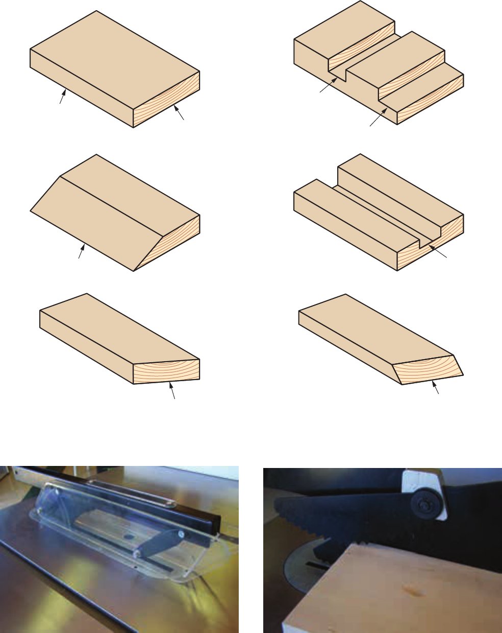
Beveling
A bevel is an angled cut along an edge of a
board. To cut a bevel on the table saw, the blade
must be tilted. Turn the saw tilt handwheel to the
correct angle. Always check the saw blade angle
with a sliding T-bevel and protractor, Figure6-20.
The saw-mounted gauge is seldom accurate
enough for nish cutting. Place one edge against
the fence and push the board with your hand or
push stick.
Since you will be cutting at an angle, the
blade may need to be raised to cut all the way
Goodheart-Willcox Publisher
Figure6-19. This featherboard was made in the
woodshop.
Goodheart-Willcox Publisher
Figure6-20. Don’t depend on the saw’s angle
gauge to be accurate. Always check the angle
with a protractor and sliding T-bevel.
Goodheart-Willcox Publisher
Figure6-21. The miter gauge on most table saws
is preset to 45°.
Ch06_126-191.indd 135Ch06_126-191.indd 135 22-09-2022 12:23:5322-09-2022 12:23:53
SAMPLE

136 Chapter 6 Power Woodworking Machines
Copyright Goodheart-Willcox Co., Inc.
Sawing a Rabbet
A rabbet is a type of wood joint commonly
used in drawer and cabinet construction. One-
half the thickness of the wood is removed so
another piece can t into position.
Lay out the size of the rabbet on the end of
the stock and set the blade to this height. Place
the stock at on the table with the marked edge
next to the fence. Use a push stick to move the
board into the saw as if you were ripping stock.
Place the edge of the board against the fence and
make the second cut. See
Figure6-23.
Cutting a Groove
or Dado
Grooves and dadoes are other types of wood
joints used in cabinet construction. Grooves run
parallel with the grain of the wood. Dadoes run
across the grain of the wood,
Figure6-24.
Grooves and dadoes are usually cut with a
dado head. A dado head makes a wide cut in a
piece of stock. Dado heads should not be used
to cut all the way through stock. Two types of
dado heads are available,
Figure6-25. One type
consists of two saw blades and a set of chip-
pers with cutting edges varying from 1/16″ to
1/4″ wide. The chippers are set up between the
blades to the width of the desired cut. Dadoes or
grooves ranging from 1/8″ to 13/16″ wide can be
made. The other type of dado head consists of
three parts. In this type of dado head, the center
piece (containing the cutters) is turned to adjust
Goodheart-Willcox Publisher
Figure6-22. A shop-made miter sled makes it
easy to cut miter joints on the circular saw.
A
B
Goodheart-Willcox Publisher
Figure6-23. Sawing a rabbet. A—Making the
first cut. B—Making the second cut.
the blade to the desired width. This type of dado
head is easy to use and provides a good, clean
cut. In either case, a different throat plate must be
installed to allow clearance for the wider blade.
When cutting a groove or dado, adjust the
dado head to the width and depth of the cut de-
sired. Check these settings using a scrap piece of
stock. Use a push stick to move the stock slowly
into the dado head as in ripping. Make sure you
hold the stock securely, since the dado head is
removing more stock than a standard blade.
Cutting a Tenon
A tenon is a projecting piece of wood
designed to t into a mortise (groove or slot).
Mortise-and-tenon joints are commonly used in
furniture construction and cabinetmaking.
Ch06_126-191.indd 136Ch06_126-191.indd 136 22-09-2022 12:23:5422-09-2022 12:23:54
SAMPLE

Section 6.1 Table Saw 137
Copyright Goodheart-Willcox Co., Inc.
However, a dado head is suggested to reduce the
number of steps required.
First, set up the dado head to the width of the
shoulder of the tenon. Install the proper throat
plate. Adjust the height of the dado head to the
depth of the tenon shoulder. Place the tenoning
jig in the miter groove. Firmly clamp a piece of
scrap lumber the same size as the tenon stock
into the jig. Keep the saw turned off and move the
tenoning jig toward the dado head. Stop just as
the stock begins to touch the dado head. Adjust
the stops on the tenoning jig for the left shoulder
and tighten the lock nut. Repeat this procedure
for the right shoulder. Move the jig away from
the dado head. Turn on the motor and make a
test cut. Adjust the jig as necessary before using
the nish stock.
A
Goodheart-Willcox Publisher
Figure6-24. The dado cut is used in many wood
projects.
Goodheart-Willcox Publisher
Figure6-25. The adjustable, or wobble, cut
blade shown on the left is the most versatile
dado blade. The width of the cut is set by turning
the dial.
B
Goodheart-Willcox Publisher
Figure6-26. Cutting a tenon using a tenoning
jig. A—Make adjustments for the left shoulder.
B—Make adjustments for the right shoulder.
To make a tenon, material is removed from
both sides of the stock. A table saw with a ten-
oning jig will cut an accurate tenon safely,
Figure 6-26. A standard rip blade, combination
blade, or dado head can be used to cut a tenon.
Ch06_126-191.indd 137Ch06_126-191.indd 137 22-09-2022 12:23:5522-09-2022 12:23:55
SAMPLE

Copyright Goodheart-Willcox Co., Inc.
138 Chapter 6 Power Woodworking Machines
5. True or False? A movable fence on the table
saw is used for accurate ripping of stock.
6. The _____ is used to aid in crosscutting and
mitering pieces of stock.
A. fence
B. guard
C. miter gauge
D. splitter
7. True or False? The table saw blade should
not be raised more than 2″ above the stock.
8. The blade that has both crosscut and rip
teeth and is used for all-purpose cutting on
the table saw is a _____ blade.
A. crosscut
B. rip
C. dado
D. combination
9. True or False? If you need to crosscut several
pieces of stock all to the same length, a stop
block should be attached to the fence.
10. When ripping long stock, the _____ stand
can be used to support the stock as it comes
off the saw table.
A. outfeed stand
B. miter gauge
C. featherboard
D. tenoning jig
11. A _____ is an angled cut along the edge of a
board.
A. bevel
B. miter
C. groove
D. None of the above.
12. True or False? Miters are angled cuts made
across a board.
13. True or False? Sawing a rabbet requires three
cuts.
14. True or False? Grooves run across the grain
of the wood.
15. True or False? To make a tenon, material is
removed from one side of the stock.
Know and Understand
Answer the following questions based on the
information provided in this section.
1. True or False? Only the person operating the
power saw needs to wear eye protection.
2. The guard on the table saw protects fingers
and hands and also deflects _____ from the
eyes.
A. sawdust
B. kickback
C. splinters
D. None of the above.
3. True or False? The anti-kickback device is
designed to prevent kickback or to reduce
the speed of a piece of stock if a kickback
occurs.
4. The _____ is used to hold the kerf open
when ripping with a table saw.
A. splitter
B. guard
C. fence
D. miter gauge
Going Green
Many of the power woodworking
machines create sawdust and
chips while performing cutting or
drilling processes. After using these
machines, one should sweep up
all of the sawdust and save it. This
sawdust works great when applied
to any spilled liquids on the floor. The
sawdust will absorb the liquid and
then it can be swept up and placed in
a container.
Ch06_126-191.indd 138Ch06_126-191.indd 138 22-09-2022 12:23:5522-09-2022 12:23:55
SAMPLE

Copyright Goodheart-Willcox Co., Inc. Section 6.2 Band Saw 139
The distance between the tabletop and the
upper blade guide determines the maximum
thickness of stock the band saw can cut. This
distance is usually 4″–6″.
Blades for the 14″ band saw are available in
widths from 1/8″ to 1″.
Figure 6-28 shows the
minimum radius that can be cut by a given
blade width. Do not cut a radius that is smaller
than what the blade can handle safely. Band
saw blades are available in a variety of tooth
sizes and styles. The proper tooth style or size
is determined by the type of material being cut
Section 6.2
Band Saw
Objectives
After studying this section, you will be able to:
• List the basic safety rules to follow when
using the band saw.
• Discuss how to select the appropriate blade
for a procedure on the band saw.
• Demonstrate how to make rough and
nished cuts, curved cuts, and bevel cuts.
• Demonstrate resawing.
Technical Terms
band saw
pad sawing
resawing
The band saw,
Figure6-27, has a wide variety
of uses. It can make straight or curved cuts, with
or without a guide. It can cut wood, plastic, and
metal.
The blade of a band saw is a continuous steel
band that revolves on two wheels, one below the
table and one above it. The upper wheel is ad-
justable to tighten or loosen the blade. It can also
be tilted forward and backward to adjust track-
ing of the blade so that it “rides” in the middle of
the wheel.
The size of a band saw is determined by the
distance from the blade to the back of the saw.
Normally, this distance is the same as the diam-
eter of the wheels. The band saws used in most
school woodshops range in size from 10″ to 14″.
Reading Prep
Before reading this section, flip
through the pages and make notes of
the major headings. Compare these
headings to the objectives. What did
you discover? How will this help you
prepare to read new material?
Delta International Machinery Corp.
Figure6-27. The band saw blade cuts with a
downward motion.
75
1
/2 2
1
/2 1
1
/2
5
/8
5
/16
3
/16
3
/16
1
/4
1
/8
3
/8
1
/2
5
/8
3
/4
1
4
Minimum Radius of Cut
Blade Width
Goodheart-Willcox Publisher
Figure6-28. Blade guide for selecting the proper
blade width for the curve radius being cut.
Ch06_126-191.indd 139Ch06_126-191.indd 139 22-09-2022 12:23:5622-09-2022 12:23:56
SAMPLE

140 Chapter 6 Power Woodworking Machines
Copyright Goodheart-Willcox Co., Inc.
• Keep your hands to the side of the
blade, away from the blade’s path.
• Keep your fingers at least 2″ from the
blade at all times. Use a fixture to hold
small pieces.
• Make relief cuts when sawing curves
that have a small radius.
• Work within the capacity of the saw. A
thick piece of stock must be fed into the
blade more slowly than a thin piece.
• If the blade breaks, step aside and
disconnect the electricity to the
machine.
• Observe the safety zone around the
band saw. If a blade breaks, it will
occasionally “climb” out to the right
side of the operator.
• Do not back out of stock unless the
blade is at a dead stop.
• Do not use your fingers to remove
scraps around the blade.
• Do not try to stop the blade with any
kind of force.
• Freehand sawing on the band saw
should be done only when very dark
lines have been drawn on the stock.
• If the machine is making unusual
noises, turn it off and notify the
instructor.
Finishing the Job
• When you are finished making your
cut, turn off the machine and let the
blade come to a complete stop. Use a
push stick to clear scraps away from
the blade.
• Never leave the saw unattended while
the blade is still moving.
and the coarseness of the cut you want to ob-
tain. The total length of the blade is specied
by the band saw manufacturer.
The upper and lower guide assemblies
should be checked frequently. Always consult
the instructor if the saw is out of adjustment.
The blade guides should clear the blade by about
0.003″ (approximately the thickness of a piece of
paper). The roller supports (backing bearings)
should clear the back of the blade by about 1/32″.
S A F E T Y
Safe Use of the Band Saw
Keep yourself and the work area
safe. Always wear appropriate personal
protective equipment, inspect the
workpiece, and obtain your instructor’s
permission before operating the band
saw. Make sure others will not be in the
machine’s safety zone while you are
operating it. Be sure to follow the general
safety rules, as well as the ones listedhere.
Before Turning on the Power
• Make all adjustments before the
power is turned on.
• Always keep the upper guide
assembly 1/8″–1/4″ above the stock.
This prevents an excess amount of the
blade from being exposed.
• Plan your sawing procedure so there
will be maximum forward feed and a
minimum of backing out.
• If you will be cutting cylindrical stock,
clamp it or use a special holding
device.
• Never turn the band saw on with the
wheel guards off.
While Cutting
• Place the stock on the table so it lies
flat and firm.
• Allow the saw to reach full speed
before starting to cut. Push the stock
forward rather than to the side.
Making Rough Cuts
Lay out the cuts to be made on the stock and
consider the sequence of the cuts. Short cuts
should be made rst,
Figure 6-29. Straight cuts
should be made before curved cuts. To save time,
Ch06_126-191.indd 140Ch06_126-191.indd 140 22-09-2022 12:23:5622-09-2022 12:23:56
SAMPLE

Section 6.2 Band Saw 141
Copyright Goodheart-Willcox Co., Inc.
to guide the material. The rate of speed will de-
pend on the type of wood and also on its thick-
ness. Narrow, straight stock (less than 3″ wide) is
ripped using a fence and a push stick,
Figure6-31.
Making Finished Cuts
In order to make nished cuts on the band
saw, you will have to use the fence attachment or
the miter gauge. These two devices are similar to
the ones used on the table saw discussed previ-
ously in this chapter. The wood stock should be
surfaced so it lies at on the table, and one edge
of the board should also be straight so it will lie
at against the fence.
Making Curved Cuts
One of the main uses of the band saw is the
cutting of curved lines. Depending on the size
of the curved cuts, special care may be needed
to prevent the blade from straining or twisting.
For sharp curved cuts, it might be advisable to
make relief cuts into the waste material before
starting to cut the curve,
Figure6-32. The relief
cuts will help prevent the binding of the blade
as it makes the turns in the wood. Refer again
to
Figure6-29, which shows the relationship be-
tween the width of a blade and the radius it will
cut without twisting or straining.
duplicate pieces can be cut on the band saw by
rst fastening the wood pieces together with sev-
eral nails driven into the waste area,
Figure6-30.
This method is called pad sawing or multiple
sawing.
Before starting the cut, place the stock on
thesaw table and adjust the guidepost so thatthe
upper guide assembly is about 1/4″ above
the work. Have the instructor check the setup
before you turn on the machine. When cutting,
keep your hands to the sides of the cutting line,
out of the direct line of the saw blade. Use only
enough forward pressure to keep the blade cut-
ting. You should feed the wood stock into the
blade using your right hand. Use your left hand
Goodheart-Willcox Publisher
Figure6-29. Planning the cuts carefully helps to
eliminate mistakes.
Goodheart-Willcox Publisher
Figure6-30. Multiple pieces can be cut at one
time on the band saw. Fasten pieces together by
nailing in the waste area.
Goodheart-Willcox Publisher
Figure6-31. Keep your fingers away from the
moving blade by using a push stick.
Ch06_126-191.indd 141Ch06_126-191.indd 141 22-09-2022 12:23:5722-09-2022 12:23:57
SAMPLE

Copyright Goodheart-Willcox Co., Inc.
142 Chapter 6 Power Woodworking Machines
on most band saws by using the tilt scale. If the
band saw does not have a tilt scale, then set the
desired angle using a T-bevel. If you are making
a straight bevel cut, you will have to use the rip
fence or miter gauge.
Know and Understand
Answer the following questions based on the
information provided in this section.
1. True or False? A band saw can only be used
to cut curves.
2. True or False? The band saw has a
continuous blade that revolves on two
wheels.
3. What determines the maximum thickness
of stock that can be cut on the band saw?
A. Type of wood
B. Size of the blade
C. Distance between the tabletop and
upper blade guide
D. None of the above.
4. Blades for the 14″ band saw are available in
widths from 1/8″ to _____.
A. 2″
B. 3″
C. 1″
D. 4″
5. True or False? When using the band saw,
keep your hands to the side of the blade.
6. True or False? Pad sawing is used to make
duplicate pieces of stock.
Resawing
Resawing is done to reduce the thickness of
stock. Instead of reducing the thickness of the
wood by surfacing, you cut off the excess material
on the band saw. A guide must be clamped to the
table,
Figure6-33. This guide will help produce
an accurate cut. The blade used in this operation
should be at least 1/2″wide.
Bevel Cuts
Most band saws have tables or heads that
will tilt to various angles for bevel cutting,
Figure6-34. The angle of the tilt can be adjusted
Goodheart-Willcox Publisher
Figure6-32. Relief cuts will help prevent
breaking the blade.
Goodheart-Willcox Publisher
Figure6-33. Resaw stock on the band saw to
avoid having to surface the material to make it
thinner.
Goodheart-Willcox Publisher
Figure6-34. The table on the band saw can be
adjusted to various angles for bevel cuts.
Ch06_126-191.indd 142Ch06_126-191.indd 142 22-09-2022 12:23:5722-09-2022 12:23:57
SAMPLE
143
Copyright Goodheart-Willcox Co., Inc.
9. True or False? Resawing is done to reduce
the thickness of stock.
10. The table on most band saws can be tilted to
various angles to allow for _____ cutting.
A. bevel
B. dado
C. rabbet
D. curved
7. In order to make finished cuts on the
band saw, you will have to use the fence
attachment or the _____.
A. miter gauge
B. tilt table
C. push stick
D. None of the above.
8. To keep the blade from straining or
twisting on a sharp curve, you should make
_____ cuts into the material before starting
the curve cut.
A. straight
B. bevel
C. dado
D. relief
Ch06_126-191.indd 143Ch06_126-191.indd 143 22-09-2022 12:23:5722-09-2022 12:23:57
SAMPLE

144 Chapter 6 Power Woodworking Machines Copyright Goodheart-Willcox Co., Inc.
the back of the arm. The blade moves up and
down, cutting only on the downward stroke like
any other scroll saw. The motor pulls the blade
down, and the tension sleeve pulls the blade up.
The number of strokes (up and down cycles) per
minute may be changed by either moving a belt
on a cone pulley or by an adjustable pulley.
The other two types of scroll saws are
constant- tension saws, meaning that the blade
always has a certain amount of tension. These
saws are capable of doing very detailed work
in stock up to 2″ thick. Blade breakage tends to
be less of a problem with the constant-tension
saws. In addition, the proper blade will allow
you to actually turn around in the kerf.
Many different blades are available for these
saws. The type of blade to use depends onthe
kind and thickness of the stock, as well as
the diameter of the curves being cut. Almost all
blades for scroll saws are 5″ long. The teeth of
the blade must point downward toward the table
when installed.
When using a xed arm saw, adjust the ten-
sion sleeve to prevent binding of the blade during
a cycle (one up stroke and one down stroke). The
pressure foot, or hold-down, should be placed
snugly on top of the stock being cut,
Figure6-36.
On a constant-tension scroll saw, the blade is
brought under tension with an adjusting knob
located at the back of the saw. The thumbscrew
just above the blade in the front of the overarm
should not be tight. However, it should be low-
ered just enough to prevent the upper blade
clamp from popping out if a blade breaks. If this
Section 6.3
Scroll Saw
Objectives
After studying this section, you will be able to:
• List the basic safety rules to follow when
using the scroll saw.
• Identify the main parts of the scroll saw and
tell what adjustments should be made to
perform various operations.
• Demonstrate internal cuts, stack cutting,
and marquetry sawing on the scroll saw.
Technical Terms
marquetry
scroll saw
stack cutting
Reading Prep
Before reading this section, make a
list of safety rules for use with the
scroll saw. After reading the section,
compare your list to the actual list.
What, if any, safety rules did you
overlook?
A scroll saw, or jigsaw, is used to cut arcs or
curves in stock,
Figure6-35. This power saw al-
lows you to perform the same tasks as with the
coping saw, but more quickly and with greater
accuracy. These saws are fun to operate and
are probably the safest of the power tools in the
woodshop. While some woodworkers distin-
guish between scroll saws and jigsaws, in this
textbook the terms are used interchangeably.
Scroll saws are available in three basic designs:
the xed (or rigid) arm saw, the C-frame constant-
tension saw, and the parallel arm constant- tension
saw. Each of these saws has its own features,
advantages, and benets.
The xed arm saw will cut stock up to about
1″ thick. The maximum length of stock that can
be cut is equal to the distance from the blade to
Goodheart-Willcox Publisher
Figure6-35. Scroll saws are used by novice and
experienced woodworkers.
Ch06_126-191.indd 144Ch06_126-191.indd 144 22-09-2022 12:23:5822-09-2022 12:23:58
SAMPLE

Section 6.3 Scroll Saw 145
Copyright Goodheart-Willcox Co., Inc.
• Push the stock forward rather than
toward the sides.
• Keep the hold-down adjusted properly
to prevent the wood from being raised
off the table.
thumbscrew is tightened against the upper blade
clamp, blade breakage is likely to occur. The
hold-down is used more for guiding the blade
and for safety reasons rather than actually hold-
ing the stock being cut.
Goodheart-Willcox Publisher
Figure6-36. Make sure the pressure foot is
holding the workpiece down onto the table.
S A F E T Y
Safe Use of the Scroll Saw
Keep yourself and the work area
safe. Always wear appropriate personal
protective equipment, inspect the
workpiece, and obtain your instructor’s
permission before operating the scroll
saw. Make sure others will not be in
the machine’s safety zone while you
are operating it. Be sure to follow the
generalsafety rules, as well as the ones
listed here.
• Unplug the saw before making any
adjustments.
• Make sure that the blade is installed
properly with the teeth pointing down.
• Turn the saw by hand before turning
on the power. This ensures that the
blade is not binding.
• Keep your fingers away from the front
of the saw blade and out of the cutting
path at all times.
Goodheart-Willcox Publisher
Figure6-37. The starter hole for internal cuts
should be the same size as the blade.
Making an Internal Cut
The procedure for making an internal cut
with a scroll saw is similar to making an inter-
nal cut with a coping saw. First, make sure the
scroll saw is unplugged. Drill a hole with a large
enough diameter to insert the blade in the waste
area of the stock near the cutting line. Loosen the
guidepost and the hold-down. If you are using
a xed arm saw, turn the machine to the down-
ward stroke by hand. Place the blade (teeth point-
ing downward) through the stock to be cut and
through the hole in the table,
Figure6-37. Insert
the blade end into the lower blade clamp. Place
the other end of the blade in the upper blade
clamp and adjust the blade tension. Finally, place
the hold-down in position. Until you become fa-
miliar with this procedure, have your instructor
check the setup before turning on the saw.
When sawing, guide the work with both
hands, pushing forward just fast enough to keep
the saw cutting. Do not cut sharp bends; they
can be cut out later. Avoid starting a cut in the
Ch06_126-191.indd 145Ch06_126-191.indd 145 22-09-2022 12:23:5822-09-2022 12:23:58
SAMPLE

146 Chapter 6 Power Woodworking Machines
Copyright Goodheart-Willcox Co., Inc.
Marquetry Sawing
Marquetry, or inlay, is a technique for form-
ing designs in wood. Two or more kinds of wood
are fastened together to make a stack. A very-ne
blade is installed in the saw. A small drill is used
to make a hole into which the scroll saw blade is
placed to start the cut,
Figure6-40. After the cut
has been made, the two pieces are interchanged
to form a unique design,
Figure6-41.
The table on the scroll saw can be placed at a
6° angle when making marquetry cuts. The cuts
are then made on only one side of the blade. This
is done so when the two pieces are pressed to-
gether, they will t tightly and the saw kerf will
be closed.
middle of a straight or slightly curved area. In-
stead, start a cut at an endpoint. Use relief cuts
whenever possible, but avoid making them too
deep. Relief cuts allow waste to break loose as
you saw your workpiece. Each relief cut should
be made almost to the cutting line. Do not over-
cut because these marks are very difcult to
sand out later.
Stack Cutting
Stack cutting is the process of fastening two
or more thin pieces of wood together and sawing
them all at the same time. This process not only
saves time but also ensures that all the items will
be the same size and shape.
The most important thing in stack cutting is
keeping all of the pieces together without shift-
ing. This can be done in several ways. Using
brads or nails is the quickest and easiest method
of holding the pieces together,
Figure6-38. Make
sure each layer is at and tight to the next layer.
There should not be any gaps between the lay-
ers. The layers could also be kept together with
staples, double-sided tape, or adhesive applied
with a hot glue gun. Keep in mind that the to-
tal thickness of all the layers should not exceed
the maximum thickness your scroll saw can cut.
Figure6-39 shows the duplicate parts made by
stack cutting.
Goodheart-Willcox Publisher
Figure6-38. Brads or nails can be used to hold
the pieces together.
Goodheart-Willcox Publisher
Figure6-39. The cut pieces are all the same size
and shape.
Goodheart-Willcox Publisher
Figure6-40. Have the instructor check your
setup before starting the cut.
Ch06_126-191.indd 146Ch06_126-191.indd 146 22-09-2022 12:23:5822-09-2022 12:23:58
SAMPLE

147
Copyright Goodheart-Willcox Co., Inc.
2. Scroll saws are available in three basic
designs: _____.
A. fixed, C-frame, parallel
B. parallel, jointer, miter
C. miter, C-frame, parallel
D. None of the above.
3. True or False? The blade on the scroll saw
moves up and down and cuts only on the
upward stroke.
4. True or False? The hold-down foot on the
scroll saw holds down the stock snugly
against the table.
5. True or False? When making an internal cut
with a scroll saw, it is necessary to first drill
a small hole in the waste area of the stock.
6. True or False? For stack cutting, the wood
pieces can be held together with tape.
7. _____ is a technique in which two or more
kinds of wood are cut and combined to
form a design.
A. Marquetry
B. Stack cutting
C. Internal cutting
D. None of the above.
Goodheart-Willcox Publisher
Figure6-41. The wood pieces chosen for
marquetry usually have contrasting colors, grain
patterns, or both.
Know and Understand
Answer the following questions based on the
information provided in this section.
1. Another common name for the scroll saw is
_____.
A. table saw
B. jointer
C. jigsaw
D. drill press
Ch06_126-191.indd 147Ch06_126-191.indd 147 22-09-2022 12:23:5822-09-2022 12:23:58
SAMPLE

148 Chapter 6 Power Woodworking Machines Copyright Goodheart-Willcox Co., Inc.
length. The tilting head makes it possible to cut
angles on the ends of stock. In addition, if the
overarm is set at an angle other than 90°, nearly
perfect compound angles can be cut.
A number of accessories made for the table
saw can also be used with the radial arm saw.
These include sanding discs, molding heads,
and dado heads. Other accessories designed just
for the radial arm saw include Jacobs chucks,
cutoff stops, mitering jigs, drum sanders, and
pin router devices.
The radial arm saw blade cuts into the wood-
en table with each cut that is made. To reduce
damage, use small nails or brads to attach a 1/4″
thick piece of plywood to the original top. Make
sure the nails are not in the blade’s path. When
the plywood top is scored with saw cuts, simply
replace it.
Crosscutting on the radial arm saw is
somewhat different than on the table saw.
Stock is pushed through on the table saw. On
the radial arm saw, the motor-blade assembly
slides along the overarm and cuts through the
stock. However, for cutting grooves or ripping,
the stock is pushed through the blade as on the
table saw.
Section 6.4
Radial Arm Saw
Objectives
After studying this section, you will be able to:
• Name the major parts of the radial arm saw
and their function.
• List the basic safety rules to follow when
using this machine.
• Demonstrate the proper method of
crosscutting and ripping.
• Demonstrate the proper method of cutting
dadoes, grooves, miters, bevels, and
compound miters.
Technical Terms
compound miter radial arm saw
Reading Prep
Before reading this section, skim the
Know and Understand questions at
the end of the section. Use them to
help you focus on the most important
concepts as you read the chapter.
A radial arm saw is sometimes described as
a circular saw on rails,
Figure6-42. The head con-
tains the motor-blade assembly and slides along
a horizontal overarm track. The head can swivel
and tilt, and the arm itself can also be adjusted.
The size of a radial arm saw is determined by the
diameter of the blade. The most common sizes
are 10″ and 12″.
The radial arm saw was originally designed
for very accurate crosscutting at a 90° angle, as
well as other desired angles. It is now commonly
used in the woodshop for rough cutting stock to
Blade
Lo
wer guard
Yo ke
Column
Angle scale
Elevating handle
Radial arm
Fence
Upper guar
d
Miter scale
Ta ble
Delta International Machinery Corp.
Figure6-42. The parts of a radial arm saw
Ch06_126-191.indd 148Ch06_126-191.indd 148 22-09-2022 12:23:5922-09-2022 12:23:59
SAMPLE

Section 6.4 Radial Arm Saw 149
Copyright Goodheart-Willcox Co., Inc.
• When ripping stock, make sure the
splitter and anti-kickback device are
properly adjusted.
• When ripping, make sure to feed the
stock into the blade against the blade
rotation, and not in the direction of
therotation. The bottom teeth should
be turning toward you.
Finishing the Job
• Always return the motor-blade
assembly to the rear of the saw after
making a cut. All saws under OSHA
regulations must return automatically.
• Wait until the blade has stopped
turning before leaving the saw. All
newer models have an automatic
brake to stop the blade.
S A F E T Y
Safe Use of the Radial Arm Saw
Keep yourself and the work area
safe. Always wear appropriate personal
protective equipment, inspect the
workpiece, and obtain your instructor’s
permission before operating the radial
arm saw. Make sure others will not
be in the machine’s safety zone while
you are operating it. Be sure to follow
general safety rules, as well as the ones
listedhere.
Before Turning on the Power
• Make all adjustments before the
power is turned on.
• Make sure the blade guard and
sawdust deflector are set properly for
the cut that is planned.
• Check the relationship of theblade
to the slot cut into the fence and
the groove cut into the table. Adjust
thefence as necessary to align all
three.
• Have the instructor check the setup
before you begin cutting.
While Cutting
• Allow the saw blade to reach its full
speed before beginning to cut stock.
• Keep your hand that is not on the
motor-blade assembly at least 6″ from
the blade and the cutting path. Tuck
your thumb under your hand. Hold
the stock in position with the heel of
yourhand.
• Cut only one piece of stock at a time.
Do not stack pieces or place them
edge to edge because you could lose
control of the stock.
• Always hold the stock firmly against
the fence for all crosscutting
operations.
Crosscutting
In crosscutting, the stock is held against the
fence, and the blade is pulled through the stock.
Before you cut, make sure the blade is properly
attached to the motor. As you look at the end of
the motor, the blade should rotate in a clockwise
direction. Be sure that the fence and movable
portion of the table have been rmly tightened.
When preparing for a 90° crosscut, rst place
a steel square against the fence, aligned with the
path of the saw blade. Gently pull the saw along
the square with the power turned off. The teeth
of the blade should be the same distance away
from the square at all points along the blade
path. If there is any variance, consult the owner’s
manual for proper saw adjustment. Remove the
steel square and any other tools from the table
before making your cut.
After determining the squareness, turn on
the power and lower the blade into the table un-
til it makes a cut 1/8″–1/4″ in depth. Pull the saw
along its entire path. The saw kerf clearly indi-
cates the blade’s path. Turn off the saw.
Carefully mark and square the desired cut-
ting location on your stock. Align this mark with
Ch06_126-191.indd 149Ch06_126-191.indd 149 22-09-2022 12:23:5922-09-2022 12:23:59
SAMPLE

150 Chapter 6 Power Woodworking Machines
Copyright Goodheart-Willcox Co., Inc.
back of the blade, the power of the motor will
force the stock to “shoot” under the blade with-
out being cut, and without your control. This is a
very hazardous situation.
Most radial arm saws allow the motor-blade
assembly and carriage to be rotated either left
or right for in-ripping or out-ripping operations.
The width of the stock being ripped and the size
of the saw determine whether to set the saw for
in-ripping or out-ripping.
Disconnect the power to the radial arm saw.
Raise the carriage slightly above the table and
rotate the head either left or right depending on
the width of the cut. Secure the head into posi-
tion. Loosen the carriage locknut and pull the
carriage until the desired width is obtained be-
tween the fence and the saw blade. Tighten the
carriage locknut. Check this measurement with
a rule and adjust as necessary.
Reconnect the power and turn on the saw.
Lower the blade into the table about 1/8″– 1/4″.
Turn the power off and rotate the blade guard to
approximately 1/4″ above the stock. Adjust and
align the anti-kickback device and splitter. Refer
to the owner’s manual for specic adjustment pro-
cedures. Make sure one edge of the stock has been
squared. Place this edge against the fence. Turn
on the power and feed the stock into the blade.
Continue the cut using a push stick if necessary.
Cutting Dadoes and
Grooves
Dadoes and grooves can be cut on the ra-
dial arm saw by mounting a dado head on the
saw arbor. The advantage in making these
cuts on the radial arm saw instead of the table
saw is that you can see the cuts being made on
the stock surface that is facing up,
Figure6-45.
If you are using a full-width dado head, you
might not be able to use the outside collar
that fits on the saw arbor. If you cannot get
thecollar on the arbor, make sure that the nut
is turned on the full depth of the threads.
Make all adjustments and set up the saw
in the same way as for crosscutting. Lower the
blade to the correct depth of your dado or groove.
After you have made this depth adjustment,
make a practice cut on a scrap piece of stock.
Measure the depth of the cut. If it is not correct,
the cut made in the fence. Make sure the saw
kerf will be made in the waste portion of your
stock. Firmly hold the stock against the fence,
keeping your hands away from the blade path.
Turn on the saw and gently pull the saw through
the stock,
Figure6-43. Be prepared to use some
backward pressure on the saw carriage as the
blade cuts through the stock. Return the saw to
its original position and turn off the saw. Check
the cut for squareness.
Ripping
When ripping stock, remember that the blade
rotates into the stock at the front of the blade, not
the back,
Figure6-44. If the stock is fed from the
Goodheart-Willcox Publisher
Figure6-43. Crosscutting on the radial arm saw.
Goodheart-Willcox Publisher
Figure6-44. Ripping on the radial arm saw.
Ch06_126-191.indd 150Ch06_126-191.indd 150 22-09-2022 12:23:5922-09-2022 12:23:59
SAMPLE

Section 6.4 Radial Arm Saw 151
Copyright Goodheart-Willcox Co., Inc.
also similar to crosscutting. However, before you
make a bevel cut, rst raise the arm of the saw so
the blade is clear of the table. Then tilt the mo-
tor to the desired angle of the cut you wish to
make. Next, lower the arm until the blade will
cut about 1/16″ into the table. Now follow the
same procedures as crosscutting.
Compound miters consist of both a miter cut
and bevel cut made at the same time. In this pro-
cess the arm is adjusted rst to the proper mi-
ter angle. Next the motor is tilted to the proper
angle. After both of these adjustments are made,
you can make your cut,
Figure6-47.
raise or lower the blade until the proper depth is
reached. You should also check to make sure the
width of the cut is correct. If it is not correct, you
will have to add or remove some of the inside
blades until you have the proper width. Some-
times you might have to add paper ller inserts
to achieve the correct width.
When you are ready to make your cut, place
the workpiece on the table with your layout lines
facing up. Place the stock rmly against the saw
fence. Check the alignment of the dado head
with the layout lines. If everything is correct,
turn on the machine and pull the blade slowly
through the stock.
If you are making grooves, use the same
dado head set to the correct width for the groove.
The machine setup should be the same as if you
are ripping stock, and the same procedures and
safety precautions should be followed.
Cutting Bevels, Miters,
and Compound Miters
It is easier to cut bevels, miters, and com-
pound miters on a radial arm saw than on a table
saw. The main advantage of using the radial arm
saw is that the stock is stationary. You can see the
cut being made, and large pieces can be handled
very easily.
If you are making a miter cut across the
grain of the wood, follow the same procedures
as for crosscutting,
Figure6-46. The bevel cut is
Goodheart-Willcox Publisher
Figure6-45. Cutting dadoes on the radial arm
saw allows you to see the cut as it is being
made.
Goodheart-Willcox Publisher
Figure6-46. To make miter cuts on the radial
arm saw, adjust the arm to the desired angle and
proceed as with crosscutting.
Goodheart-Willcox Publisher
Figure6-47. A compound miter (miter plus
bevel) is cut by changing the blade angle and the
arm angle.
Ch06_126-191.indd 151Ch06_126-191.indd 151 22-09-2022 12:24:0022-09-2022 12:24:00
SAMPLE

Copyright Goodheart-Willcox Co., Inc.
152 Chapter 6 Power Woodworking Machines
5. Grooves can be cut with the radial arm saw
by mounting a _____ on the saw arbor.
A. locknut
B. sanding disc
C. dado head
D. splitter
6. True or False? Cutting bevels and miters
on the radial arm saw is similar to
crosscutting.
7. In compound miter cuts, a miter and _____
are cut at the same time.
A. bevel
B. dado
C. rabbet
D. chamfer
Know and Understand
Answer the following questions based on the
information provided in this section.
1. True or False? The radial arm saw was
originally designed for ripping stock to
width.
2. Today, the radial arm saw is commonly
used for _____.
A. 90° crosscutting
B. ripping
C. cutting grooves
D. dado cutting
3. True or False On the radial arm saw, the
motor-blade assembly slides along the
overarm.
4. True or False When ripping on the radial
arm saw, the blade rotates into the stock at
the front of the blade, not the back.
Ch06_126-191.indd 152Ch06_126-191.indd 152 22-09-2022 12:24:0022-09-2022 12:24:00
SAMPLE

Copyright Goodheart-Willcox Co., Inc. Section 6.5 Drill Press 153
Various drill speeds can be obtained by ei-
ther a variable pulley or step pulleys. The slow-
est speed, usually 400–600 rpm, should be used
to bore holes 1″ in diameter or larger. A speed of
1200 rpm can generally be used to drill holes up
to 1/2″ in diameter.
S A F E T Y
Safe Use of the Drill Press
Keep yourself and the work area
safe. Always wear appropriate personal
protective equipment, inspect the
workpiece, and obtain your instructor’s
permission before operating the drill
press. Make sure others will not be in
the machine’s safety zone while you are
operating it. Be sure to follow general
safety rules, as well as the ones listed
here.
• Unplug the drill press before making
adjustments.
• Never use a dull drill bit; a sharp bit
will produce better results and is less
apt to break.
• Clamp all stock to the drill press table
before drilling holes. Make sure that
you have a piece of scrap lumber
under your stock to keep the bit from
drilling into the table after it goes
through the workpiece. The scrap
piece will also prevent splintering as
the bit goes through the underside of
the workpiece.
• Place the hole in the center of the
table directly under the drill bit to
prevent the drill from striking the
table.
• Always make sure the chuck key has
been removed from the chuck prior to
turning on the drill.
• Have your instructor check the setup
prior to turning on the drill press.
Section 6.5
Drill Press
Objectives
After studying this section, you will be able to:
• Name the main parts of the drill press and
their functions.
• List the basic safety rules to follow when
using the machine.
• Demonstrate the proper method of drilling
holes in at and round wood stock.
• Demonstrate the proper method of drilling
holes at an angle.
• Describe how to use a drill press for cutting
large holes, sanding, boring duplicate holes,
and mortising.
Technical Terms
circle cutter
drill press
sanding drum
V-block
Reading Prep
Read the section title and write a
paragraph describing what you know
about this power tool. After reading
the section, summarize what you have
learned.
A drill press has a vertically mounted drill
bit that is raised and lowered toward a table.
The drill press is used to drill holes in wood and
other materials. It can also be used for sanding,
routing, shaping, and mortising. Drill press size
is twice the distance from the center of the drill
bit to the column. A 15″ drill press, for example,
will drill a hole 7 1/2″ from the edge of a piece
of stock.
Ch06_126-191.indd 153Ch06_126-191.indd 153 22-09-2022 12:24:0022-09-2022 12:24:00
SAMPLE

154 Chapter 6 Power Woodworking Machines
Copyright Goodheart-Willcox Co., Inc.
Figure6-49. Place a scrap board under the stock
to be drilled and use some type of mechanical
holding device (drill press vise or clamp) to hold
both pieces in place.
Turn on the drill. Make sure your hands are
clear of the path of the drill bit. Bring the bit into
cutting position with the feed lever using light
pressure. If the hole is deep, remove the bit from
the stock several times to pull out the chips and
to prevent the bit from overheating. When the
hole is completed, return the bit to its original
position by rotating the feed lever in the opposite
direction. Do not let the feed wheel snap back.
Shut off the motor and wait for the chuck to stop.
Drilling Round Stock
Round or irregularly shaped stock should be
held in a V-block,
Figure6-50, or in a drill press
vise, or it can be clamped to the table. If possi-
ble, the table should be turned for drilling into
large pieces. Follow the same procedures as per-
formed for drilling at stock.
• Do not force the bit into the stock.
Feed only fast enough for the drill to
cut well.
• Release the pressure when the drill
goes through the wood stock.
• Withdraw the drill frequently when
drilling deep holes to prevent
“burning” and “freezing” of the drill in
the stock.
• Bore large-diameter holes at the
slowest drill press speed.
Goodheart-Willcox Publisher
Figure6-48. The chuck key has been attached to
the drill press column to keep it from being lost.
Before drilling, remove the key from the chuck
and make sure it will not interfere with your
work.
Drilling Flat Stock
Lay out and mark the holes to be drilled as
you would when using hand tools. Select the
correct size bit, insert it in the chuck, and tight-
en the chuck with the chuck key,
Figure6-48.
Make sure you remove the chuck key after
tightening.
Center the table under the drill bit. Adjust the
drill press for the proper chuck speed. (The speed
on some drill presses must be changed while the
motor is turned on.) Set the depth gauge if you
do not wish to drill all the way through the piece,
Goodheart-Willcox Publisher
Figure6-49. The depth gauge controls the depth
of the hole to be drilled.
Ch06_126-191.indd 154Ch06_126-191.indd 154 22-09-2022 12:24:0022-09-2022 12:24:00
SAMPLE

Section 6.5 Drill Press 155
Copyright Goodheart-Willcox Co., Inc.
hands are out of the way before turning on the
power. Proceed slowly as you feed the cutter or
hole saw into the stock.
Sanding on the Drill
Press
Sanding drums are available in many sizes
and with abrasive sleeves of various grits,
Figure 6-52. The main sanding operation
performed on the drill press is edge sanding.
The sanding operation should be done at a high-
er rate of speed. The proper speed should be
Drilling Holes at an
Angle
Holes can be drilled at an angle by tilting the
drill press table. It can be difcult to keep the
drill bit from drifting off center. To prevent this,
take a piece of scrap stock and cut an angle across
one end equal to the angle of the drill press ta-
ble. This angle, which will be perpendicular to
the drill bit, enables you to cut straight into the
stock without straying. Set the drill press table
at the correct angle using a sliding T-bevel. Place
a piece of scrap lumber below the stock and put
the scrap lumber with the angle above the stock.
Clamp everything to the table. Perform the drill-
ing operation as you would when drilling at
stock.
Cutting Large Holes
Cut large holes in stock using either a circle
cutter or a hole saw,
Figure6-51. If using a circle
cutter, set it to the correct size before attaching
it to the machine. Make sure the center drill bit
is set about 1/4″ below the cutter so it can guide
and anchor the cutter.
Adjust the drill press to its slowest speed.
Clamp the stock to the drill table and have your
instructor check the setup. Make sure your
Goodheart-Willcox Publisher
Figure6-50. The V-block can be made in the
shop. It can also be used on the band saw when
cutting round stock.
A
B
Goodheart-Willcox Publisher
Figure6-51. Cutting large holes. A—The circle
cutter can be preset to cut holes at any diameter.
B—Hole saws can be purchased singly or as a
set that includes several sizes.
Ch06_126-191.indd 155Ch06_126-191.indd 155 22-09-2022 12:24:0122-09-2022 12:24:01
SAMPLE

156 Chapter 6 Power Woodworking Machines
Copyright Goodheart-Willcox Co., Inc.
Boring Duplicate
Holes
When building a wood product, you might
need to bore several holes of the same size.
You can save yourself some time by building a
simple fixture or making a special setup. The
fixture for boring duplicate holes might consist
of an auxiliary table with a stationary fence.
If you clamp this fixture in the proper posi-
tion, you can bore a series of holes by moving
the stock along the fence. Marks can be placed
on the fence to indicate the center-to-center
distance between the holes, Figure6-54.
Mortising
If your wood project requires mortise-
and-tenon joints, you can use the drill press
to cut the mortise holes. You will need a mor-
tising attachment,
Figure 6-55. It consists of
a hollow, square mortising chisel in which
an auger bit rotates. The chisel is ground to
a very sharp point at each corner. After the
auger bit enters the wood, the sharp points of
the chisel cut the square opening.
Make sure the chisel is the same width
as the mortise to be cut. The workpiece you
are cutting should t against the fence that
is attached to the table. This fence will help
between750 rpmto 1500 rpm, if you are using
a variable speed drill press with the capacity to
change the speeds. Otherwise, you will have
torefer to the instruction manual, which will
show you how to change the position of the
belts to obtain different speeds. If possible, use
an auxiliary table that has an open throat larger
than the sanding drum.
For faster removal of wood material, you can
use a drum rasp,
Figure6-53. The drum rasp ts
into the drill chuck the same way as the sanding
drum, and it is used in the same manner. How-
ever, it will leave a rough edge that will require
sanding.
Goodheart-Willcox Publisher
Figure6-52. The sleeves for the sanding drum
come in various grit sizes.
Goodheart-Willcox Publisher
Figure6-53. The drum rasp removes wood very
quickly, but the surface will have to be fine-
sanded later.
Goodheart-Willcox Publisher
Figure6-54. With this fixture, duplicate holes
can be made quickly.
Ch06_126-191.indd 156Ch06_126-191.indd 156 22-09-2022 12:24:0222-09-2022 12:24:02
SAMPLE

157
Copyright Goodheart-Willcox Co., Inc.
• Keep your hands away from the chisel
while operating the machine.
• After mortising, don’t touch the bit
because it will be hot.
guide the stock and ensure the proper dimen-
sion for the mortise. Mortising attachments
usually come with a stock hold-down that
attaches to the drill press table and keeps the
stock in place.
Goodheart-Willcox Publisher
Figure6-55. Mortise holes can be drilled with a
mortising attachment on the drill press.
Know and Understand
Answer the following questions based on the
information provided in this section.
1. True or False? Drill press size is twice the
distance from the center of the drill bit to
the column.
2. True or False? To bore holes that are 1″ or
larger in diameter, you should use the
slowest speed on the drill press.
3. A piece of scrap stock should be placed
under the workpiece before drilling _____.
A. to hold both pieces in place.
B. to make a smooth hole
C. to prevent burning the wood
D. None of the above.
4. The _____ on the drill press is used to
tighten the chuck and secure the bits.
A. V-block
B. chuck key
C. depth gauge
D. None of the above.
5. True or False? The depth gauge is designed
to keep you from drilling all the way
through the material.
6. To drill round stock, clamp it to the drill
press table or hold it in a _____.
A. clamp
B. V-block
C. vise
D. hand
7. True or False? Cutting large holes can be
done with a hole saw or circle cutter.
8. To remove material quickly, use a _____
rather than a sanding drum.
A. file
B. hand plane
C. sandpaper
D. drum rasp
9. True or False? A mortising attachment
consists of a hollow chisel and an
augerbit.
S A F E T Y
Safety Rules for Mortising
Follow all safety rules for using the drill
press. In addition, observe the following
rules when mortising.
• Check the bit and chisel. They must
be sharp and securely fastened in the
drill press before it is started.
• Set the table low enough so the
chisel will not strike it or the clamped
scrap stock at the bottom of the
cutting stroke.
• Clamp all stock securely in position
before starting the cut.
Ch06_126-191.indd 157Ch06_126-191.indd 157 22-09-2022 12:24:0222-09-2022 12:24:02
SAMPLE

158 Chapter 6 Power Woodworking Machines Copyright Goodheart-Willcox Co., Inc.
of cut. The adjustment is made with either the
handwheel or an adjustment lever located below
the infeed table. The outfeed table must be set
even with the cutting edges of the knives at their
highest point in their rotation. The outfeed table
should be locked in this position if straight cuts
are desired. The fence is used to guide stock as
it is pushed from the infeed table to the outfeed
table. The fence may be moved in or out to ac-
commodate different widths of stock. It may also
be tilted to make angular cuts. The cutter guard
is positioned over the cutterhead to protect the
operator from injury and to protect the edges
of the knives from damage. The cutter guard
is spring loaded. When stock is fed across the
jointer, the guard only exposes a small amount
of the cutterhead and knives.
Figure6-57 shows
a cross-sectional view of the jointer.
Section 6.6
Jointer
Objectives
After studying this section, you will be able to:
• Name the main parts of the jointer and their
function.
• List the basic safety rules to follow when
using this machine.
• Demonstrate the proper methods of jointing
the edge and surface of stock.
Technical Terms
infeed table
jointer
outfeed table
Reading Prep
As you read this section, list each
of the jointer processes described.
Include the specific details of each
process, such as the steps involved.
A jointer is used to remove warp and other
surface imperfections from the edges and faces
of stock to make it straight and true. Straight and
true stock is necessary to ensure that other op-
erations, such as sawing and drilling, will pro-
duce square (perpendicular) cuts and holes. The
jointer is also used to cut chamfers, bevels, rab-
bets, and tapers.
The size of the jointer is specied by the
length of its knives. The knives are the parts of
the jointer that actually do the cutting. A jointer
usually has three knives, which rotate in a cutter-
head at about 4500 rpm. The jointer is equipped
with an infeed table, outfeed table, fence, and
cutter guard,
Figure 6-56. The infeed table, or
front table, is adjusted to the desired depth
Fence
Base
Infeed
table
Outfeed
table
Depth
scale
Power switch
Delta International Machinery Corp.
Figure6-56. A jointer is used to surface the face,
edge, or end grain of wood.
Fence
Wood stock
Outfeed table Infeed table
Cutter head
Goodheart-Willcox Publisher
Figure6-57. Jointer operation. The cutterhead
rotates clockwise, and the stock is fed into it.
Ch06_126-191.indd 158Ch06_126-191.indd 158 22-09-2022 12:24:0322-09-2022 12:24:03
SAMPLE

Section 6.6 Jointer 159
Copyright Goodheart-Willcox Co., Inc.
Stock Size and Depth
of Cut Limitations
Stock to be smoothed on a jointer should be
at least 12″ long. This allows a good portion of
the stock to be on the outfeed table as the last
portion of the stock is leaving the infeed table.
For jointing the surface of stock, the minimum
surface width should be 1″ and the minimum
thickness should be 3/8″. For jointing the edge
of stock, the minimum surface width should be
2″–3″, and the minimum thickness should
be 3/8″,
Figure 6-58. These dimensions allow
you to keep your ngers well above the cutters.
Variations of these minimums are possible
withthe use of special jigs and xtures designed
for theoperator’s protection.
Stock that projects beyond the length of the
infeed table by more than 18″ should be jointed
by two people. The operator should be in control
of feeding the stock, while the assistant should
balance the weight of the stock. It is good prac-
tice to carefully plan your work to avoid jointing
short pieces. Stock that is 48″–60″ long is a man-
ageable length. Stock that is 10″–12″ long should
be cut into two or three manageable pieces prior
to jointing, unless the long lengths are necessary
for the product.
The depth of cut depends on the width
and hardness of the stock, as well as the feed
rate. Generally, lumber that is hard and wide
should be fed slowly into the jointer. Maximum
recommended depth of cut for hardwoods is
1/32″–1/16″. Softwoods may be jointed using
a1/16″–1/8″ depth of cut.
12″
12″
12″
2–3″
3
/8″
3
/
8″
1″
Outfeed table Infeed table
Minimum Length of Stock for All Operations
Surface Jointing Minimum Dimensions
Edge Jointing Minimum Dimensions
Goodheart-Willcox Publisher
Figure6-58. Minimum stock dimensions for the jointer.
Ch06_126-191.indd 159Ch06_126-191.indd 159 22-09-2022 12:24:0322-09-2022 12:24:03
SAMPLE

160 Chapter 6 Power Woodworking Machines
Copyright Goodheart-Willcox Co., Inc.
• Do not stand directly behind the
infeed table. Stand to the left of the
infeed table to protect yourself from
kickback.
• Feed the stock so the knives cut with
the grain.
• Keep your hands at least 4″ away from
the knives and cutterhead.
• Change the position of your hands
so they do not pass directly over the
cutterhead when feeding the stock,
and never drag your thumb or fingers
behind the stock.
• Use a push stick or push block for
planing flat surfaces and jointing
narrow edges.
• Hold the stock firmly on the table or
against the fence as it is run over the
jointer.
• Surface cupped stock with the
concave side down. This allows you to
have two points of the stock in contact
with the table.
• When jointing long pieces of stock,
have a helper support the end so it
doesn’t drop.
Finishing the Job
• When you are finished, turn off the
machine and let it come to a complete
stop before clearing away scraps.
• Never leave the jointer unattended
while the knives are still moving.
S A F E T Y
Safe Use of the Jointer
Keep yourself and the work area
safe. Always wear appropriate personal
protective equipment, inspect the
workpiece, and obtain your instructor’s
permission before operating the jointer.
Make sure others will not be in the
machine’s safety zone while you are
operating it. Be sure to follow general
safety rules, as well as those listed here.
Before Turning on the Power
• Make sure the stock is within the
recommended limits for thickness,
width, and length. It should be free
from knots, splits, and foreign objects
such as nails or screws.
• Do not attempt to run odd-shaped
pieces, such as round stock, over the
jointer.
• Jointer knives must be kept sharp. Dull
knives cause vibration and poor cuts.
• Adjust the depth of cut before the
power is turned on. Do not remove
more than 1/8″ at a time for edge
jointing or more than 1/16″ for
surfacing.
• Never change the adjustment of the
outfeed table unless the instructor has
asked that it be done.
• Make sure the area beyond the infeed
table is clear before turning on the
motor.
• Adjust and lock the fence before
turning the jointer on.
• Do not attempt to operate the jointer
without the guard in proper position.
While Cutting
• Keep the guard closed over the knives
at all times while the jointer is being
used. Do not pull the guard open with
your fingers.
Jointing Edges
Adjust the fence so it is square with the infeed
table. To do this, place the handle of a try square
on the infeed table and rest the blade along the
fence,
Figure6-59. When the fence is in the prop-
er position, lock it in place. Set the depth of cut
for 1/32″–1/16″ using the handwheel or adjust-
ment lever. You might want to check your setup
at this time by using a piece of scrap lumber of
the same species as the nish stock. When you
Ch06_126-191.indd 160Ch06_126-191.indd 160 22-09-2022 12:24:0322-09-2022 12:24:03
SAMPLE

Section 6.6 Jointer 161
Copyright Goodheart-Willcox Co., Inc.
to apply pressure against the fence and outfeed
table at the end of the stroke,
Figure6-62.
Narrow pieces can be jointed safely by using
a push stick. Make sure that you have the push
stick in hand before starting the jointing opera-
tion. The left hand should be lifted across the
cutterhead to apply pressure to the piece against
the fence and outfeed table.
Planing Surfaces
The surface, or face, of the stock must be true
before laying out other measurements. The rst
surface, or working surface, is smoothed with a
have determined that you have the correct setup,
inspect your nish stock to determine the grain
direction. Turn the stock so the knives will cut
with the grain.
Make sure the guard is in its proper position
over the cutterhead. Place the stock on its edge
on the infeed table. Rest the surface of the stock
against the fence. Stand to the left of the jointer
and turn on the motor. Allow the cutterhead to
come to full speed.
Hold the stock rmly against the fence and
infeed table while pushing it over the cutter-
head,
Figure6-60. When about a foot of the stock
has passed over the cutterhead, lift your left
hand from its original position and apply pres-
sure on the stock against the fence and outfeed
table with that hand,
Figure6-61. Use both hands
Goodheart-Willcox Publisher
Figure6-59. Make all adjustments while the
machine is in the “off” position.
Goodheart-Willcox Publisher
Figure6-60. Applying pressure on the fence and
infeed table.
Goodheart-Willcox Publisher
Figure6-61. Never allow your hands to pass over
the top of the cutterhead on the jointer. Lift your
left hand from its original position and then place
it down on the stock over the outfeed table.
Goodheart-Willcox Publisher
Figure6-62. Applying pressure on the fence and
outfeed table.
Ch06_126-191.indd 161Ch06_126-191.indd 161 22-09-2022 12:24:0422-09-2022 12:24:04
SAMPLE

162 Chapter 6 Power Woodworking Machines
Copyright Goodheart-Willcox Co., Inc.
and infeed table while pushing the stock over
the knives toward the outfeed table. Gradually
shift the pressure to the outfeed table as the cut
is completed. Continue to push the stock across
the jointer until the guard snaps back over the
cutterhead.
Planing a Taper
If your project calls for a taper, like on a table
leg, the jointer can make this simple cut with
some minor adjustment. Here are the steps you
will need to make:
1. Lay out the taper on the wood.
2. Mark a line on the wood where you want
the taper to start.
3. Place the stock on the infeed table of the
jointer about 1/2″ beyond the high point of
the jointer knives.
4. Clamp a stop block onto the infeed table so
it just touches the end of the taper.
5. Start the machine and place the stock
against the stop block, then lower the stock
onto the blade. Using a push stick move
the stock forward until the cut is finished,
Figure6-64. When making the cut, keep
firm pressure on the infeed table side of
the stock.
6. Continue making the taper cuts until
youreach the lines you have marked on
the stock.
jointer. Set the depth of cut for 1/32″. A smaller
depth of cut is required for surface planing than
for edge jointing because you will be removing
stock from a larger surface area. Turn the stock
so the knives will cut with the grain. Make sure
you have a push stick or push block in one of
your hands,
Figure6-63. Step to the side of the
jointer, make sure the guard is in its correct posi-
tion, and turn on the motor. Allow it to come to
full speed.
If the stock is warped, place it on the in-
feed table with the cupped surface down. Use
a push stick to apply pressure against the fence
Goodheart-Willcox Publisher
Figure6-63. Smoothing the surface of stock
using a push block.
Goodheart-Willcox Publisher.
Figure6-64. Taper cuts for making table legs
can be easily made on the jointer.
Ch06_126-191.indd 162Ch06_126-191.indd 162 22-09-2022 12:24:0422-09-2022 12:24:04
SAMPLE

163
Copyright Goodheart-Willcox Co., Inc.
Know and Understand
Answer the following questions based on the
information provided in this section.
1. True or False? The outfeed table must be set
even with the cutting edge of the jointer
knives.
2. The _____ is used to guide stock as it is
pushed from the infeed table to the outfeed
table.
A. cutter guard
B. fence
C. depth gauge
D. None of the above.
3. True or False? The proper depth of cut
depends on the width and hardness of the
stock and on the feed rate.
4. When jointing stock, where should you
stand in relation to the infeed table?
A. To the right of the infeed table.
B. To the left of the infeed table.
C. Behind the cutter blades.
D. None of the above.
5. True or False? The cupped surface of stock
should be placed down when jointing it.
6. When cutting a bevel one should _____.
A. adjust the fence at desired angle
B. hold stock firmly against the fence
C. keep hands 4” away from the blades
D. All of the above.
Planing Bevels and
Chamfers
In order to cut bevels and chamfers on the
jointer, the fence is set at an angle. Machines
will vary in the way this adjustment will be
made. You can set the angle of the fence either
away from the jointer table or toward the table,
Figure 6-65. Once the fence is set at the proper
angle, push the stock through several times until
the proper bevel or chamfer is cut.
Goodheart-Willcox Publisher.
Figure6-65. Bevels and chamfers can be cut on
the jointer by tilting the fence.
Ch06_126-191.indd 163Ch06_126-191.indd 163 22-09-2022 12:24:0422-09-2022 12:24:04
SAMPLE

164 Chapter 6 Power Woodworking Machines Copyright Goodheart-Willcox Co., Inc.
Depth of cut is set by adjusting the table. The
smooth outfeed rollers grasp and pull thestock
as it passes below the cutterhead. The combina-
tion of the infeed and outfeed rollers ensures
a smooth, even feed of the stock across the
cutterhead.
Section 6.7
Planer/Surfacer
Objectives
After studying this section, you will be able to:
• Name the main parts of the planer and their
function.
• List the basic safety rules to follow when
using this machine.
• Calculate the correct depth of cut.
• Plane at stock to proper thickness.
Technical Terms
backing board
planer
surfacer
Reading Prep
Before reading this section, make
a list of the power woodworking
machinery you have learned about
so far in Chapter 6. Add the planer/
surfacer to your list and write a brief
description of how you think this
machine functions.
The planer, or surfacer, is used to machine
stock to exact thickness. A planer is equipped
with a cutterhead that usually contains
threeknives, similar to a jointer. However, un-
like the jointer, the planer cuts the stock on the
top surface. The size of a planer is specied
bythe length of the knives and the thickness of
thestock it willaccept. Common planer sizes
for the woodshop are 12″, 18″, and 24″.
A planer is equipped with four feed rollers:
two infeed and two outfeed. The upper infeed
roller, which is milled or corrugated to grip the
stock, and the lower infeed roller pull the stock
through the cutterhead. The chip breaker and
the pressure bar hold the stock down as it is fed
through the machine,
Figure6-66.
Pressure bar
Platen Stock
Lower outfeed
roller
Lower infeed
roller
Chip breaker
Upper outfeed
roller
Upper infeed
roller
Knife
Cutterhead
Feed direction
Goodheart-Willcox Publisher
Figure6-66. Planer operation. Note the position
of the parts and the feed direction.
S A F E T Y
Safe Use of the Planer
Keep yourself and the work area
safe. Always wear appropriate personal
protective equipment, inspect the
workpiece, and obtain your instructor’s
permission before operating the
planer. Make sure others will not be
in the machine’s safety zone while
you are operating it. Be sure to follow
general safety rules, as well as the ones
listedhere.
Before Turning on the Power
• Never surface a piece of stock shorter
than the recommended minimum
length. Consult the instructor or
operation manual if this information
is not posted on the machine. The
minimum length of stock to be used
with most planers is 12″–16″.
Ch06_126-191.indd 164Ch06_126-191.indd 164 22-09-2022 12:24:0522-09-2022 12:24:05
SAMPLE

Section 6.7 Planer/Surfacer 165
Copyright Goodheart-Willcox Co., Inc.
Planing Stock
The stock to be planed must have one true
face. This face is rst smoothed on the jointer.
The cupped shape of defective stock will not be
removed by using only the planer. Instead, the
feed mechanism of the planer will atten the
stock before the stock enters the cutterhead. As
the stock leaves the planer, it will return to its
original shape.
Measure the stock at its thickest point to de-
termine its dimension. Set the planer for this
thickness minus the depth of cut. For example,
if the stock is 13/16″ thick and the depth of cut
is 1/16″, set the planer to 12/16″, or 3/4″. The rec-
ommended depth of cut is 1/32″–1/16″ for hard-
woods and 1/16″–1/8″ for softwoods. Make sure
that your stock is long enough to pass through
the planer without getting caught. The mini-
mum length of stock to be used with most plan-
ers is 12″–16″.
Position the stock so the knives will cut with
the grain. Make sure the true surface is down.
Grasp the board with both hands, one on each
side of the stock. Hold the stock horizontally and
allow the infeed rollers to pull the board across
the cutterhead. Make sure that you do not have
your ngers between the stock and the infeed
table. Stand to the side of the stock as you feed it;
do not stand directly behind the stock. Walk to
the back of the planer to receive the board.
Reset the depth of cut and make additional
cuts until the desired thickness is obtained.
When planing stock that is 6′ or more in length,
either have an assistant “tail off” or use an out-
feed stand to support the stock. If the stock is not
properly supported, its weight pulling down-
ward could result in an uneven nish thickness
or cause damage to the planer.
Planing Thin Stock
The minimum thickness that should be
planed on the machine is 1/4″. If you need to
plane a board that is thinner than 1/4″, then you
must use a backing board,
Figure6-67. Place the
thin stock on top of the backing board and set
your depth of cut to the desired thickness. Make
sure you allow for the thickness of the backing
board. For example, if your backing board is 3/4″
• Limit the depth of cut to 1/8″ for
narrow stock and 1/16″ for stock that
is wider. If more stock needs to be
removed, run the stock through the
planer again.
• Do not plane stock that is less than
1/4″ thick unless it is placed on a thick
board for support.
• Make all adjustments before the
power is turned on.
• Wait for the motor to reach full speed
before you start to feed the stock into
the planer.
While Cutting
• Stand to the side of the stock when
feeding. Do not stand directly behind
the stock.
• Hold the stock in a horizontal position
and with both hands as it is fed into
the planer.
• Feed stock so the planer knives cut
with the grain.
• Only one board should be planed at a
time.
• Wide stock and hardwood stock
should be fed at slow speeds. The
depth of cut should also be reduced.
• Do not change the depth of cut
while the board is going through the
machine.
• Never look into the mouth of the
planer while it is running. Chips of
wood can fly out of the planer with
great force.
• If stock gets caught or turns sideways,
stop the machine and call the instructor.
Finishing the Job
• When you are finished with the planer,
turn off the machine and let the planer
come to a complete stop before
clearing away chips.
• Never leave the planer unattended
while it is still moving.
Ch06_126-191.indd 165Ch06_126-191.indd 165 22-09-2022 12:24:0522-09-2022 12:24:05
SAMPLE

Copyright Goodheart-Willcox Co., Inc.
166 Chapter 6 Power Woodworking Machines
thick and the thickness of the stock you want to
plane is 1/4″, then set the depth gauge to 7/8″.
This will allow the machine to make the mini-
mum cut of 1/8″.
Know and Understand
Answer the following questions based on the
information provided in this section.
1. True or False? The lower infeed roller of a
planer is milled or corrugated to grip the
stock.
2. True or False? The rate of feed for softwoods
is slower than for hardwoods.
3. True or False? The depth of cut should be
reduced when cutting hardwoods.
4. Suppose you have a piece of hardwood
stock that is 1″ thick. You want to plane it to
7/8 ″ thickness. At least _____ passes will be
needed to achieve this thickness.
A. one
B. two
C. three
D. four
5. True or False? Stock less than 1/4″ thick can
be planed if it is placed on top of a backing
board.
Goodheart-Willcox Publisher
Figure6-67. If you must plane thin stock, use a
backing board under it.
Ch06_126-191.indd 166Ch06_126-191.indd 166 22-09-2022 12:24:0522-09-2022 12:24:05
SAMPLE

Copyright Goodheart-Willcox Co., Inc. Section 6.8 Wood Lathe 167
Many wood products are cylindrical or cir-
cular in shape. Some examples are bowls, lamp
bases, table legs, and rails for chairs. These
items can be shaped on the wood lathe. The
shaping process is called wood turning.
Thewood stock is shaped with turning tools.
The tools are supported by a tool rest as the
stock rotates. In spindle turning, the work-
piece is held between centers on the lathe’s
headstock and tailstock. In headstock turning
(faceplate turning), a metal disc called a face-
plate is mounted on the headstock, and the
workpiece is fastened to this disc.
The headstock is usually at the left side of
the lathe bed and is permanently fastened to it.
It has a hollow, threaded spindle that is powered
by the motor. The motion of the spindle causes
the workpiece to rotate. The spindle can be t-
ted with a spur center (for spindle turning) or a
faceplate (for headstock turning).
The tailstock is usually located on the
right side of the lathe. Unlike the headstock,
it can slide back and forth along the lathe
bed; so it can be adjusted for the length of the
workpiece. The tailstock also has a spindle. For
most spindle turning, a cup center is inserted in
this spindleto hold one end of the workpiece.
Thetailstock is not used in faceplate turning.
The tool rest (tool support) can be moved
to various positions along the lathe bed. To
accommodate the size of the workpiece being
turned, the tool rest can also be moved up
ordown.
The lathe can be set to turn at various
speeds. The proper turning speed is very impor-
tant for safety. The diameter of the wood stock
will determine what speed should be used.
The table in Figure6-68 will help you select the
properspeeds.
Also keep in mind the following general
rules about proper speeds on the lathe:
• Always begin turning at a slow speed.
• Slow speeds will help keep the tools sharp.
• Sanding should be done at higher speeds
but not to the point where the abrasive
paper heats and glazes.
Section 6.8
Wood Lathe
Objectives
After studying this section, you will be able to:
• Identify the major parts of the wood lathe.
• List the basic safety rules to follow when
using this machine.
• Identify the six common turning tools and
their uses.
• Demonstrate how to prepare wood stock for
turning between centers.
• Demonstrate how to prepare wood stock for
faceplate turning.
• Demonstrate how to cut rough stock to a
cylindrical shape using the gouge.
• Demonstrate how to make nishing cuts
using the skew.
• Demonstrate how to cut tapers, shoulders,
beads, V-grooves, and coves.
• Demonstrate how to smooth stock on the
lathe by sanding.
• Demonstrate how to apply a French polish.
Technical Terms
bead
cove
headstock turning
lathe
spindle
spindle turning
taper
tool rest
wood turning
Reading Prep
Before reading this section, review
the highlighted terms within the body.
Determine the meaning of each term.
Ch06_126-191.indd 167Ch06_126-191.indd 167 22-09-2022 12:24:0522-09-2022 12:24:05
SAMPLE

168 Chapter 6 Power Woodworking Machines
Copyright Goodheart-Willcox Co., Inc.
• Make sure the stock is fastened
securely. On faceplate work, screws
must be checked frequently to prevent
loosening.
• Adjust and keep the tool rest as close
to the stock as possible without
touching the stock.
• Rotate the stock by hand to make
certain it does not touch any part of
the lathe.
• Saw stock that is to be used for
faceplate work into a circular
shapebefore fastening it to the
faceplate.
• Follow the instructor’s directions
exactly when changing the speed
control setting.
• Remove the tool rest for sanding or
polishing work on the lathe.
While Working
• Stand to one side when the power is
first turned on.
• Use slow speeds for faceplate work on
large-diameter stock.
• Never attempt a shearing cut until
special instruction and permission
have been given by the instructor.
S A F E T Y
Safe Use of the Wood Lathe
Keep yourself and the work area
safe. Always wear appropriate personal
protective equipment, inspect the
workpiece, and obtain your instructor’s
permission before operating the lathe.
Make sure others will not be in the
machine’s safety zone while you are
operating it. Be sure to follow general
safety rules, as well as the ones listed
here.
Before Turning on the Power
• Allow adequate drying time
before turning glued stock. (See
manufacturer’s instructions for
different glues.)
• Make sure the turning tools you will
be using are sharp.
• Square turning stock should have all
corners cut at 45° angles. Check to be
sure ends are properly marked and
kerfed.
• Make all adjustments and
measurements when the lathe is
turned off. Oil, grease, or soap should
be placed in the dead center cup.
Lathe Turning Speeds
Diameter of Stock
Rough Turning to Size
(rpm) General Cutting (rpm) Finishing Speed (rpm)
Under 2″
900–1300 2400–2800 3000–4000
2″–4″
600–1000 1800–2400 2400–3000
4″–6″
600–800 1200–1800 1800–2400
6″–8″
400–600 800–1200 1200–1800
8″–10″
300–400 600–800 900–1200
Over 10″
200–300 300–500 500–900
Goodheart-Willcox Publisher
Figure6-68. Lathe speeds for various stock diameters.
Ch06_126-191.indd 168Ch06_126-191.indd 168 22-09-2022 12:24:0522-09-2022 12:24:05
SAMPLE

Section 6.8 Wood Lathe 169
Copyright Goodheart-Willcox Co., Inc.
Woodturning Tools
Six shapes of turning tools are commonly
used by wood turners,
Figure 6-69. The tools
are available in various widths, thicknesses,
and lengths.
Figure6-70 shows a complete set of
woodturning tools. The task to be performed de-
termines which tool should be used.
Gouge
A gouge is generally used to cut rough stock
to a cylindrical shape. A gouge cuts rapidly, but it
does not produce a smooth cut or surface. When
using a gouge, hold the convex side down. The
tool should be rolled 30°–45° in the direction it
is being moved along the tool rest. The cutting
edge should be slightly ahead of the handle
• Never use a gouge inside of a cup-
shaped piece.
• Be very careful never to touch the
chisel against the “up travel” side of
the faceplate work.
• Hold turning tools firmly against
the tool rest with both hands while
cutting stock on the lathe.
Finishing the Job
• When you are finished with the lathe,
turn off the machine and let it come to
a complete stop.
• Never leave the work area while the
lathe is still running.
60°
30°
25°
to
35°
60°
60°
45°
30°
60°
40°
25° for softwoods
35° for hardwoods
Gouge
Round nose
Skew
Spear point
Parting tool
Flat nose
Goodheart-Willcox Publisher
Figure6-69. Common turning tools used for wood turning.
Ch06_126-191.indd 169Ch06_126-191.indd 169 22-09-2022 12:24:0622-09-2022 12:24:06
SAMPLE

170 Chapter 6 Power Woodworking Machines
Copyright Goodheart-Willcox Co., Inc.
Skew
The skew is used to make nishing or
smoothing cuts, to cut beads and V-shaped
grooves, and to square shoulders. The skew is
placed at on the tool rest with the bevel down.
See
Figure 6-72. The tool should be held almost
level with the center of the stock. The handle can
be lowered slightly. Gently push the cutting edge
into the stock. Only the edge should contact the
material. The skew scrapes the material rather
than cutting it.
Parting Tool
The parting tool is thinner at the edges
than in the center. This shape allows you to
push the tool straight into the stock without
binding. As the name indicates, the tool is
used to part (separate) the nished part from
the rough stock. It is also valuable in establish-
ing initial diameters prior to cutting special
shapes,
Figure 6-73. This procedure provides
relief for the other cutting tools while estab-
lishing the nished depth.
when making the cuts. The bevel at the gouge
should contact the stock before the cutting edge.
This is easily accomplished by lowering the tool
handle 10°–15°. As the bevel rubs the stock, raise
the handle until the cutting edge begins to re-
move the material,
Figure6-71.
A
Goodheart-Willcox Publisher
Figure6-70. Keep all of your lathe tools sharp to
ensure proper cutting.
B
Goodheart-Willcox Publisher
Figure6-71. Using a gouge. A—Move the gouge
into the wood until the bevel touches it. B—Raise
the handle and move the edge into the wood.
Goodheart-Willcox Publisher
Figure6-72. Place the skew with its beveled
edge down.
Ch06_126-191.indd 170Ch06_126-191.indd 170 22-09-2022 12:24:0722-09-2022 12:24:07
SAMPLE

Section 6.8 Wood Lathe 171
Copyright Goodheart-Willcox Co., Inc.
To determine which wood is best for your proj-
ect, you must rst decide the purpose for the
turning. Is it to be a table leg or perhaps a candy
bowl? The purpose determines many variables.
If the turning will support a product structur-
ally, the stock must be kiln dried and straight
grained with minimal defects. However, if the
product is only decorative (such as the bowl),
defects and “wild” grain patterns can enhance
the nished appearance. Many professional
bowl turners use freshly cut wood that has been
discarded because of defects. This “wet” wood
turns very easily, and the defects add character
to their work.
Gluing Stock for Turning
For some products, several pieces of stock
may need to be glued together. This is done to
achieve the desired rough stock size, to make
allowance for the product design, for decora-
tive purposes, to stabilize a defect, or even to
allow separation of pieces after turning. See
Figure 6-75. Whenever stock is to be glued for
turning, only at and true pieces of stock should
be used. If the mating surfaces are not at, the
stock could separate during turning. This sepa-
ration could destroy the product or cause per-
sonal injury. Use a good white or yellow glue.
Do not attempt to turn glued stock until the glue
has set for at least 24 hours. Test the glued stock
by dropping it from shoulder height to the oor
to see whether it separates.
Round Nose, Spear Point,
and Flat Nose
These chisels are used when the tool shape
needs to t the contour of the work. As with the
skew, these tools usually make a scraping cut.
They are held at on the tool rest, approximate-
ly level with the center of the stock. The tool is
pushed gently into the stock with only the edge
contacting the material.
Figure 6-74 shows the
round nose tool making a cove cut.
Each of these tools is ground to a special
contour. Whenever the shape you are turn-
ing matches one of these contours, these tools
can be used to increase speed and uniformity.
Many turners will custom grind a special
shape they will be repeating into the profile
of a flat tool, such as a bull nose. You should
use extreme care when sharpening a tool
witha special contour in order not to destroy
theprofile.
Woods for Turning
Several woods can be used for turning in
the woodshop. Commonly used woods include
birch, mahogany, hard maple, oak, and walnut.
Goodheart-Willcox Publisher
Figure6-73. Parting cuts are made before
cutting special shapes so that you will know
when the stock has been cut to the required
diameter.
Goodheart-Willcox Publisher
Figure6-74. The round nose tool is used for
cove cuts and can also can be used for faceplate
turning.
Ch06_126-191.indd 171Ch06_126-191.indd 171 22-09-2022 12:24:0722-09-2022 12:24:07
SAMPLE

172 Chapter 6 Power Woodworking Machines
Copyright Goodheart-Willcox Co., Inc.
If you are faceplate turning, you can glue
a piece of scrap to the good stock. This allows
screws to be placed into the scrap without damag-
ing the nal product. Many turners glue a piece of
kraft paper between the scrap and the good stock
for easier separation later. See Figure6-76.
Some spindle-turned material will be sepa-
rated after turning and attached to a at surface
for decorative purposes. When this technique is
utilized, two pieces of stock can be glued togeth-
er, separated with a piece of kraft paper. The two
pieces are easily separated after turning. Use care
to place the center points of both lathe centers on
this glue line to assure equal separation later.
Professional wood turners commonly use
wood with defects to enhance a design. However,
Goodheart-Willcox Publisher
Figure6-75. Different types of wood can be
glued together. Turning the glued piece on the
lathe produces unique designs.
A
B
C
D
Goodheart-Willcox Publisher
Figure6-76. Gluing process. A—Glue a scrap piece of wood to the glued-up stock and then attach it
to the lathe faceplate. B—After the project has been turned, separate the scrap piece from the finished
product. C—Separating the good stock from the scrap. D—The finished bowl.
Ch06_126-191.indd 172Ch06_126-191.indd 172 22-09-2022 12:24:0922-09-2022 12:24:09
SAMPLE

Section 6.8 Wood Lathe 173
Copyright Goodheart-Willcox Co., Inc.
Mount the spur center and the stock in the
headstock spindle. Insert the cup center in the
other end of the stock. Turn the stock by hand to
seat the cup center in the end of the stock, and
then lock the tailstock into position.
Adjust the tool rest so that it is parallel with
the center of the stock and about 1/8″ away from
it,
Figure6-79. Make sure that the tool rest is not
below the center of the stock. Turn the stock by
hand to see that it clears the tool rest. Set the
lathe at the slowest speed and turn on the motor.
a loose knot could separate while turning, caus-
ing a hazard. The defect is glued in place using
a cyanoacrylate adhesive specically designed for
lathe turning. This adhesive sets almost immedi-
ately, allowing for repairs to be made to the stock
while only briey shutting the lathe off. However,
the fumes from the adhesive can irritate the eyes,
nose, and throat, and it can be extremely hazard-
ous when it comes into contact with the skin.
Spindle Turning
Spindle turning is used to make products such
as balusters, rails, and lamp bases. For spindle
turning, the stock is mounted between the lathe
centers. Select a piece of stock and cut it about an
inch longer than the completed product. Fasten
the piece in a vise and draw diagonal lines across
the corners of both ends. Then mark the centers
with a punch. Cut saw kerfs about 1/8″ deep
along the diagonal lines at one end,
Figure 6-77.
If the thickness and width of the stock are greater
than 2″ square, plane or saw off the corners prior
to turning. This decreases the amount of time re-
quired for rough turning and reduces hazards.
Drive the spur (headstock) center into the kerfs
with a mallet as shown in
Figure6-78.
Insert a cup (tailstock) center into the tail-
stock spindle. Some cup centers, called dead
centers, are stationary. These types of centers
require the use of grease or wax as a lubricant.
Some tailstock centers have bearings that rotate
with the stock. These bearing centers require
little or no lubrication.
Goodheart-Willcox Publisher
Figure6-77. The saw kerfs allow the lathe spur
to hold the wood securely when turning.
Goodheart-Willcox Publisher
Figure6-78. Drive the spur into the saw kerfs
with a mallet.
Goodheart-Willcox Publisher
Figure6-79. Always keep the tool rest as close
to the turning as possible. You will have to move
it as you keep removing material.
Ch06_126-191.indd 173Ch06_126-191.indd 173 22-09-2022 12:24:0922-09-2022 12:24:09
SAMPLE
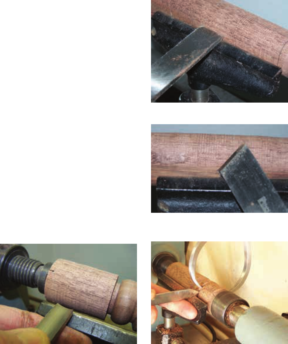
174 Chapter 6 Power Woodworking Machines
Copyright Goodheart-Willcox Co., Inc.
The speed of some lathes may need to be adjust-
ed after turning on the lathe.
Place a gouge on the tool rest, positioning one
of your hands on the blade and the other hand on
the handle. The hand on the blade should have
the thumb over the blade and forenger under
the blade,
Figure6-80. Turn the blade slightly to
make a shearing cut. Move the gouge carefully
along the tool rest using your forenger as a
guide. Make additional cuts with the gouge us-
ing the same method until the piece becomes
cylindrical. When the space between the stock
and the tool rest reaches 3/8″, stop the lathe and
readjust the tool rest. Check the progress of the
cylinder by holding the tool lightly on the top
of the moving stock. When the tool sits without
bouncing, the cylinder is nished (round).
Use a skew with a scraping cut to smooth the
cylinder,
Figure 6-81. A scraping cut is made by
turning the skew’s cutting edge at a right angle
to the piece. Move the skew along the tool rest
using a similar motion as when using the gouge
to achieve a smooth, uniform cylinder. Scraping
cuts are easier to make with the skew than shear-
ing cuts. Scraping cuts are recommended until
you have had enough experience using the lathe.
Shearing cuts are made with a skew by raising the
tool rest above center and turning the cutting edge
of the skew at an angle to the stock,
Figure6-82.
The cutting edge then cuts like aknife.
Use a parting tool and outside calipers to lay
out the necessary diameters along the cylinder.
Next, use other tools to form the desired shape
to complete the piece.
Goodheart-Willcox Publisher
Figure6-80. The first tool to use for spindle
turning is the gouge. Hold it as shown here.
Goodheart-Willcox Publisher
Figure6-81. Smoothing with the skew.
Goodheart-Willcox Publisher
Figure6-82. Making a shearing cut with the
skew.
Figure6-83 illustrates using the calipers and
the parting tool while the stock is rotating. This is
a common procedure used by many experienced
Goodheart-Willcox Publisher
Figure6-83. Check the diameter with outside
calipers at various times during the turning.
Ch06_126-191.indd 174Ch06_126-191.indd 174 22-09-2022 12:24:1022-09-2022 12:24:10
SAMPLE

Section 6.8 Wood Lathe 175
Copyright Goodheart-Willcox Co., Inc.
turners. This procedure should not be attempted
by beginners. The lathe should be turned off to
make measurements when you are learning to
turn wood.
Cutting Tapers and
Shoulders
A taper is a gradual, uniform decrease in
diameter from one end of the stock to another.
Table legs are often tapered. The rst step in cut-
ting a taper is to lay out the length of the taper
according to your plans. Using the parting tool,
turn the stock to the required diameter on each
end of the taper. Next, use the gouge to turn the
stock down to within 1/8″ the entire length of
the taper. Once you have the stock rough cut,
use the skew to turn the stock down to the n-
ish size,
Figure 6-84. This can be done using a
shearing cut. A scraping tool can also be used
to make the same kind of cut. When making the
taper, always cut from the large end toward the
smaller end.
Shoulder cuts are straight cuts made into
the stock,
Figure 6-85. The rst cut is made
with the parting tool held straight and pushed
into the rotating stock. A nish cut is then made
with the toe of the skew to produce a smooth sur-
face. If the shoulder cut is more than 3/8″ deep
into the stock, make a second cut to provide
enough clearance to prevent overheating the tool.
Beads
Beads are rounded parts on turned wood.
Making accurate beads is very difcult and will
require much practice and skill. Practice this cut
on scrap stock before attempting it on your proj-
ect. The rst step is to turn the stock down to
the correct diameter. Once this has been done,
use a ruler to lay out the positions of the beads
on the stock,
Figure6-86. Place a skew high on
the work and use the heel to make the starting
cut. Now rotate the tool from the horizontal to
vertical position. As you make this move, pull
the tool slightly toward you so that the heel will
continue to make the cut. In order to get the bead
to the desired shape and size, repeat this cut sev-
eral times until you get to the required depth,
Figure6-87.
Goodheart-Willcox Publisher
Figure6-84. The taper cut is usually done with
the skew.
Goodheart-Willcox Publisher
Figure6-85. The shoulder cut can be made with
the skew or with the parting tool.
Goodheart-Willcox Publisher
Figure6-86. Mark the locations of the cuts to be
made while the machine is running.
Ch06_126-191.indd 175Ch06_126-191.indd 175 22-09-2022 12:24:1022-09-2022 12:24:10
SAMPLE

176 Chapter 6 Power Woodworking Machines
Copyright Goodheart-Willcox Co., Inc.
Thenishing cut is made by placing the gouge
on edge and in the horizontal position and then
moving it into the cut,
Figure6-89. As you move
the gouge into the cut, you should roll the tool
and lower the handle. This action will form half
of the cove. Once you have cut one-half of the
cove, cut the other half using the same method.
Headstock Turning
Headstock turning is used to make products
such as bowls. When making a small bowl, select a
piece of turning stock that measures about 1″ thick
by 5″ square. In addition, select a smaller piece of
scrap stock to use as a separation piece. The scrap
stock provides a waste area for screwing the stock
to the faceplate. Cut both pieces to a circular shape.
Then attach the scrap to the stock with a piece of
kraft paper between the two pieces of wood. Glue
and clamp the pieces of stock and paper securely,
allowing them to dry overnight. The two pieces
can later be easily separated using a chisel.
Attach the faceplate to the scrap stock using
No. 12 wood screws as shown in Figure 6-90.
Remove the spur center from the headstock and
screw the faceplate on the headstock spindle. Set
the lathe to its slowest speed. Some lathes must
be rotating in order to change the speed. If this is
the case with your lathe, adjust the speed before
mounting the stock to the spindle. Adjust the
tool rest so that it is parallel to the center of your
stock and about 1/8″ away from it. Turn the stock
by hand to make sure that it clears the tool rest.
V-Grooves
Making V-grooves on the wood lathe is
somewhat similar to making beads. The main
difference is that V-grooves are made without
rotating the skew. The skew should be rocked
straight into the stock until the desired depth is
achieved,
Figure6-88.
Coves
Coves are concave cuts made into the wood.
A cove cut is very simple to make. Lay out the
width of the cove on the stock using a rule and
a pencil. Coves can be cut with either the round
nose chisel or a small gouge. Make a rough
cut by pushing the tool straight into the stock.
Goodheart-Willcox Publisher
Figure6-87. The bead design is cut in several
steps.
Goodheart-Willcox Publisher
Figure6-88. A V-groove is cut with the skew.
Goodheart-Willcox Publisher
Figure6-89. Using a round nose chisel to make
a cove cut.
Ch06_126-191.indd 176Ch06_126-191.indd 176 22-09-2022 12:24:1022-09-2022 12:24:10
SAMPLE
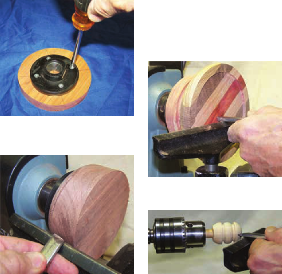
Section 6.8 Wood Lathe 177
Copyright Goodheart-Willcox Co., Inc.
when making external cuts. Continue with ad-
ditional cuts using the same method to obtain a
wall thickness of about 1/4″ and a bottom thick-
ness of about 3/8″.
Turning Small Pieces
Small pieces can be held on the lathe using a
drill press chuck mounted on the tapered shank
of the headstock. If you have several small
knobs that need to be made for your project,
this would be the perfect method to produce
the parts. The rst step is to drill a 3/8″ diam-
eter hole into a 1″ dowel rod. Glue a small piece
of 3/8″ dowel rod into the hole. Secure this 3/8″
dowel rod in the drill chuck. The desired shape
of the part can then be turned on the lathe,
Figure6-93. If you have a small faceplate project,
Rough turn the outside of the bowl with a
gouge. Then smooth it with a round nose tool.
See
Figure6-91.
Reset the tool rest so that it is parallel with
the face of the bowl,
Figure6-92. Position a round
nose tool on the tool rest and begin cutting at the
outside edge of the bowl. Move the tool carefully
along the tool rest toward the center. Remember
to scrape from the larger diameter to the smaller
diameter when making internal cuts, and from
the smaller diameter to the larger diameter
Goodheart-Willcox Publisher
Figure6-90. Attach the faceplate to the wood
with screws. Make sure the screws will not
interfere with the internal cutting of the wood.
Goodheart-Willcox Publisher
Figure6-91. Rough cutting on the outside of the
bowl is done with a gouge.
Goodheart-Willcox Publisher
Figure6-92. For cutting the inside of the bowl,
place the tool rest parallel with the bowl face.
Goodheart-Willcox Publisher
Figure6-93. A drill press chuck can be used to
hold small pieces for turning.
Ch06_126-191.indd 177Ch06_126-191.indd 177 22-09-2022 12:24:1122-09-2022 12:24:11
SAMPLE

178 Chapter 6 Power Woodworking Machines
Copyright Goodheart-Willcox Co., Inc.
Lathe Duplicator
Attachment
When several parts with the same design
are needed, a lathe duplicator attachment can be
used. This device can be attached to most lathes.
Most lathe duplicators have a guide that follows
either the original part or a template that is a sil-
houette (outline) of the original part. The tem-
plate is usually made from plastic or hardboard.
The rough stock is placed between the centers,
the lathe is turned on, and the guide is moved
along the template. An exact copy is then turned
between the centers.
you could also use the screw chuck. The screw
chuck is threaded onto the headstock. Drill
a small diameter hole in your workpiece and
then screw the workpiece onto the screw chuck,
Figure6-94. Use smaller lathe tools if they are
available,
Figure6-95.
Turning Duplicate
Parts
If your project requires two or more pieces
of the same size and shape, it is best to make a
template. The template can be used to lay out
the proper diameters,
Figure6-96. By using the
parting tool and calipers, you can cut down the
workpiece to a rough shape.
Goodheart-Willcox Publisher
Figure6-95. Smaller lathe tools such as these
are useful for turning small pieces of wood
stock.
A B
Goodheart-Willcox Publisher
Figure6-94. The use of the screw chuck should be used when turning small projects.
Goodheart-Willcox Publisher
Figure6-96. Duplicate templates should be
used when making several pieces that are the
same size.
Ch06_126-191.indd 178Ch06_126-191.indd 178 22-09-2022 12:24:1222-09-2022 12:24:12
SAMPLE

Section 6.8 Wood Lathe 179
Copyright Goodheart-Willcox Co., Inc.
for sanding. Sanding belts have a cloth backing
and, when cut into strips, allow you to hold the
ends while sanding. This can reduce or elimi-
nate frictionburns.
Applying a Finish
When your nal turning has been carefully
sanded, some nishes can be applied while the
stock is still mounted on the lathe. French pol-
ishing is a simple technique that provides an
excellent nish. Place a piece of paper under the
turning to protect the lathe bed from the nish-
ing materials. Set the lathe to a speed of 600 rpm
and turn on the motor. Fold a clean cloth into a
small pad, apply a small amount of linseed oil
to the pad, and rub the surface of the product as
shown in
Figure6-98. Next, apply shellac with
the pad held lightly against the surface. When
the product is coated, increase the speed of the
lathe to about 1200 rpm while increasing the
pressure on the pad. Use a few drops of linseed
oil on the pad as a lubricant. When the nish
becomes shiny, turn off the lathe and remove
the product. Allow the nish to harden over-
night. It will probably be necessary to apply a
second coat after the rst coat has thoroughly
dried. Apply a coat of wax after both coats of
nish have dried.
Many turners use a wax nish. The wax n-
ish is simple, fast, and very effective for many
products. While the spindle or headstock is
rotating, apply the wax directly to the wood’s
Final Sanding
After the desired shape has been turned, cer-
tain nishing operations should be completed
before removing the stock from the lathe. The
rst of these operations is sanding,
Figure6-97.
Observe the following safety precautions.
• Your hand will be contacting the turning
material. Make certain not to allow any
clothing or rags to pull your ngers into
thestock.
• Use a light touch. Sanding and polishing
generate frictional heat that can burn your
ngers if you apply too much pressure.
• As with any sanding operation, care should
be taken not to inhale the dust or to allow
excessive dust to build up on the surface of
your skin. Use a NIOSH-approved breathing
mask and position a fan to blow the dust
away from you.
• Many lathes are equipped with reversing
switches. This capability allows for faster
sanding. Do not reverse the direction
of rotation while the lathe is turning.
This could damage the lathe or cause
personalinjury.
The grit size used for sanding depends on
two factors: the type of wood and the quality
of the nish achieved using the lathe tools.
Generally, start with 80–100 grit paper and
end using 180–220 grit paper. Do not use steel
wool as it can easily wrap around the stock. Old
sanding belts can be cut into strips and used
Goodheart-Willcox Publisher
Figure6-97. Sanding can be done while the
lathe is running.
Goodheart-Willcox Publisher
Figure6-98. The materials for a French polish
are applied with a cloth.
Ch06_126-191.indd 179Ch06_126-191.indd 179 22-09-2022 12:24:1222-09-2022 12:24:12
SAMPLE

Copyright Goodheart-Willcox Co., Inc.
180 Chapter 6 Power Woodworking Machines
with a clean cloth. Allow the product to dry
several weeks before use.
Know and Understand
Answer the following questions based on the
information provided in this section.
1. In _____ turning, the workpiece is held
between centers on the lathe’s headstock
and tailstock.
A. spindle
B. tailstock
C. faceplate
D. screw chuck
2. True or False? Headstock turning is also
called faceplate turning.
3. True or False? All work turned on the lathe
should be started at a slow speed.
4. The _____ cuts rapidly but does not produce
a smooth cut or surface.
A. skew
B. parting
C. gouge
D. round nose
5. True or False? The skew is used to make
parting cuts.
6. True or False? Structural parts, such as
table legs, should be made from kiln-dried
wood.
7. True or False? Saw kerfs are cut into the
ends of wood stock that will be mounted
between centers.
8. True or False? When cutting a taper, always
cut from the large end toward the small
end.
9. Coves can be cut with a small gouge or a
_____ chisel.
A. round nose
B. gouge
C. skew
D. parting
10. When turning a product such as a bowl, the
stock and separation pieces are attached to
a ______.
A. spindle
B. faceplate
C. drill chuck
D. screw point
Goodheart-Willcox Publisher
Figure6-99. Follow the manufacturer’s
directions for using commercial finishes on
thelathe.
Goodheart-Willcox Publisher
Figure6-100. Non-toxic finishes should be used if
your turning project will be used for serving food.
surface. Allow a slight buildup of wax. Press a
clean cloth on the wax while the spindle is turn-
ing. The friction melts the wax, pushing it into
the pores of the wood surface. Applying more or
less pressure with the rag can vary the shade of
the nish. Be careful not to allow the cloth to pull
your hand into the stock.
Figure 6-99 shows other types of nishes
that can be applied to wood turnings. Please
note that if your project will come in contact
with food, it is best to apply several coats of
liquid cooking oil or similar non-toxic nish,
Figure 6-100. Wipe the material on and buff
Ch06_126-191.indd 180Ch06_126-191.indd 180 22-09-2022 12:24:1222-09-2022 12:24:12
SAMPLE
181
Copyright Goodheart-Willcox Co., Inc.
14. True or False? For final sanding on the lathe,
generally start with 80–100 grit paper and
end with 180–220 grit paper.
15. True or False? The type of finishing material
applied to turned bowl that will used for
serving food should be non-toxic.
11. True or False? Small parts can be turned
on the lathe by using a drill press chuck
attached to the headstock.
12. True or False? When several parts of the
same design are needed, a faceplate
attachment can be fastened to the lathe.
13. The French polish technique uses a
combination of linseed oil and _____.
A. shellac
B. lacquer
C. varnish
D. wax
Ch06_126-191.indd 181Ch06_126-191.indd 181 22-09-2022 12:24:1322-09-2022 12:24:13
SAMPLE

182 Chapter 6 Power Woodworking Machines Copyright Goodheart-Willcox Co., Inc.
spindle is adjustable to allow for varying depths
of cut. Once the desired height is determined,
the spindle is locked into place.
The cutter and spindle are rotated by a motor-
driven belt. Cutter speeds range from 5000 to
10,000 rpm. Some machines have variable speeds.
They make it possible to set the best cutter speed for
the type of material being cut, the thickness of the
cut, and the size of the cutter. The cutter normally
turns in a counterclockwise direction, but many
machines are equipped with reversing switches.
Straight stock is usually held against the
fence. The shaper fence is divided into two parts:
the front fence and the rear fence. Both parts of
the fence are separately adjustable. Curved stock
is fed against a depth guide collar attached to the
spindle, and one or two fulcrum pins.
Shaper Cutters
Three-lip solid cutters are available in a vari-
ety of shapes, including straight, cove, ute, bead,
door lip, and many others,
Figure 6-101. Some
cutters may be purchased for either left-hand or
Section 6.9
Shaper
Objectives
After studying this section, you will be able to:
• Identify the main parts of the shaper and
their function.
• List the basic safety rules to follow when
using this machine.
• Demonstrate the process of shaping straight
edges on wood stock.
• Demonstrate the process of shaping curved
edges on wood stock.
Technical Terms
fulcrum pin shaper
Reading Prep
As you read this section, list the
shaper cutters available and make
a sketch next to each, showing the
profile made by the cutter.
The shaper is used to cut decorative proles
into straight or irregular edges of wood stock. It
can also be used to cut simple wood joints such
as a rabbet or tongue-and-groove joint. The pro-
les are formed by various sizes and shapes of
cutters mounted onto the spindle of the machine.
The work is moved over the table and fed into the
cutters to form the desired shape. Note that many
of the operations done on the shaper can be done
somewhat more safely with a portable router. The
portable router is covered in Chapter5.
The size of a shaper is specied by the diam-
eter of the spindle that holds the cutters. Com-
mon spindle sizes are 1/2″, 3/4″, and 1″. Many
machines allow the use of different sizes of spin-
dles. The outside diameters of the cutter knives
vary a great deal, depending upon their use.
Many cutters have larger spindle holes (center
holes) as the outside diameter or overall thick-
ness of the cutter increases. The height of the
Flute
Glue joint
3-Bead 5-Bead Wedge
tongue
Wedge
groove
FluteDrawer
joint
Ogee Female
sash
Male
sash
Ogee & bead
table edge
Flute
Qr. Rd. Flute Bead Door lip
Flute Bead Panel
raising
Bead
Convex
edge
Flute Bead
Bead
Goodheart-Willcox Publisher
Figure6-101. These are some of the profiles that
can be formed by shaper cutters.
Ch06_126-191.indd 182Ch06_126-191.indd 182 22-09-2022 12:24:1322-09-2022 12:24:13
SAMPLE

Section 6.9 Shaper 183
Copyright Goodheart-Willcox Co., Inc.
• Make sure the stock is at least 16″
long. Use a featherboard or other
device to help hold stock less than 4″
wide or 1″ thick.
• Select a cutter that is designed to
cut on the underside of the stock to
eliminate cutter exposure.
• Make all adjustments before the
power is turned on.
• Make sure the knives are correctly
seated and balanced and are fastened
securely to the arbor.
• Make sure both sides of the fence are
in line when cutting straight stock.
• Select a collar size that will conform
as nearly as possible to the smallest
curve in the form to be shaped. Use
the pin in the table when “riding the
collar.”
• Always use the guard and hold-down
devices.
• Have the instructor check the setup
before turning on the power.
• Always feed the stock against the
cutting edge. In other words, feed the
work into the cutters in the direction
opposite the cutter rotation.
• Cut with the grain whenever possible.
Advance the stock very slowly when
cutting against the grain.
• Hold the stock firmly against the fence
or collar.
• Always use a fulcrum pin to help start
stock against the depth collar. This
will help prevent kickback of the stock.
• Keep your hands 6″ away from the
cutter when starting the cut.
• Use stop blocks when making a cut
within the limits of the piece of stock;
that is when the cut will not be along
the entire length of the stock.
• Never back up. Stock must always be
fed against the rotation of the cutters.
Feeding with the rotation can throw
the stock from the shaper.
right-hand operation. Cutters are made of high-
speed steel with carbide-tipped cutting edges to
increase their durability.
When possible, cutters should be installed so
that they cut from the bottom of the stock. This
allows the stock to act as a partial shield. Spacing
collars may be used above or beneath the cutter to
hold the assembly in the proper position. If irregu-
lar shapes are to be cut, a depth guide collar must
be placed above or beneath the cutter. Thecollar
regulates the depth of cut and guides the stock as
it is fed across the shaper,
Figure6-102. When cut-
ting irregular shapes, one or two fulcrum pins
must be installed to aid in starting thecut.
When installing a cutter in a shaper, discon-
nect the power cord or turn off the disconnect
switch. Remove the top spindle nut. Select the
desired cutter and install it on the spindle. Spac-
ers are generally necessary either above or below
the cutter. These should be placed on the spindle
prior to replacing the spindle nut.
S A F E T Y
Safe Use of the Wood Shaper
Keep yourself and the work area
safe. Always wear appropriate personal
protective equipment, inspect the
workpiece, and obtain your instructor’s
permission before operating the shaper.
Make sure others will not be in the
machine’s safety zone while you are
operating it. Be sure to follow general
safety rules, as well as the ones listed here.
Spindle
Washer
3-lip
cutter bit
Spindle
collar
Spindle nut
Depth guide
collar
Shaper table
Goodheart-Willcox Publisher
Figure6-102. Installing a bit on a shaper spindle.
Note the depth guide collar.
Ch06_126-191.indd 183Ch06_126-191.indd 183 22-09-2022 12:24:1322-09-2022 12:24:13
SAMPLE

184 Chapter 6 Power Woodworking Machines
Copyright Goodheart-Willcox Co., Inc.
guide collar into the cutter knives. Be sure the
knives rotate toward the stock. Continue to push
the stock forward with light pressure against
the depth guide collar. Complete the stroke by
keeping light pressure against the depth guide
collar while pushing the stock past the cutter.
Turn off the motor after the cutting stroke has
been completed.
Shaping Straight
Edges
Best results when using a shaper are obtained
after practicing on a piece of scrap stock. Select a
defect-free piece of stock that is at least 16″ long.
Install a suitable cutter on the spindle. Set the
fence in a position so that the cutter is correct-
ly aligned with the edge of the stock. Move the
fence parallel to the miter gauge slot on the table
and tighten it securely. Inspect the grain of the
stock to determine its direction. Turn the stock
so the cutter knives will cut toward the stock
and in the direction of the grain.
The process of shaping a straight edge with
a shaper is similar to that of jointing an edge
with a jointer. Place the stock on the shaper table
and turn on the motor. Hold the stock against
the table and the fence and push it over the cut-
ter. When about 2″ of the stock have passed the
cutter, turn off the motor and adjust the second
part of the fence to the formed edge,
Figure6-103.
Turn on the motor and continue the cutting
stroke. When about 8″ of the stock have passed
the cutter, move one of your hands to the other
side, then the other hand, and complete the cut-
ting stroke with both hands pressing against the
second part of the fence. This procedure ensures
that your hands will not pass directly over or in
front of the cutter,
Figure6-104.
Shaping Irregular
Edges
Select a piece of scrap stock and saw a curve
on one edge. Install a suitable cutter and a depth
guide collar on the spindle. Fasten a fulcrum pin
in the table. The fulcrum pin acts as a guide and
support when starting the cut. Turn the stock so
that the cutter knives will cut toward the stock
and in the direction of the grain. Position the
ring guard.
Place the stock on the shaper table and turn
on the motor. Hold the stock rmly against
the fulcrum pin and push it toward the depth
R
ear fence
(outfeed)
3-lip cutter
Stock
Front fence
(infeed)
Rotation
Goodheart-Willcox Publisher
Figure6-103. Offset of the shaper fence as an
entire edge is shaped (top view).
Goodheart-Willcox Publisher
Figure6-104. Keep your hands away from the
rotating blades of the shaper.
Ch06_126-191.indd 184Ch06_126-191.indd 184 22-09-2022 12:24:1422-09-2022 12:24:14
SAMPLE
185
Copyright Goodheart-Willcox Co., Inc.
3. True or False? When using the shaper, make
sure the stock is at least 3” long.
4. True or False? When shaping a straight edge,
you should move your hands from the front
fence to the rear fence.
5. The _____ acts as a guide and support when
starting irregular cuts on the shaper.
A. fence
B. fulcrum pin
C. guard
D. None of the above.
Know and Understand
Answer the following questions based on the
information provided in this section.
1. The size of the wood shaper is indicated
by the diameter of the _____ that holds the
cutter.
A. spindle
B. chuck
C. washer
D. screw
2. When possible, shaper cutters should be
installed so they cut from the _____ of the
stock.
A. right
B. bottom
C. left
D. top
Ch06_126-191.indd 185Ch06_126-191.indd 185 22-09-2022 12:24:1422-09-2022 12:24:14
SAMPLE

186 Chapter 6 Power Woodworking Machines Copyright Goodheart-Willcox Co., Inc.
S A F E T Y
Safe Use of Sanders
Keep yourself and the work area
safe. Always wear appropriate personal
protective equipment, inspect the
workpiece, and obtain your instructor’s
permission before operating power
sanders. Make sure others will not be in
the machine’s safety zone while you are
operating it. Be sure to follow general
safety rules, as well as the ones listed
here.
• The dust produced by power sanders
can be extremely hazardous if inhaled.
Proper dust collection devices should
be in place and operating. Wear a
NIOSH-approved respirator when
operating a power sander.
• Carefully inspect the condition of the
abrasive surface (belt, disc, drum, or
spindle) before turning on the power.
Surfaces that are frayed, torn, or
have holes should be replaced by the
instructor.
• On disc sanders, set the clearance
between the sanding disc and the
table so that it is as close as possible
(1/16″ or less).
• All adjustments must be made while
the sander is turned off and stopped.
• Check to be sure that all machine
guards are in place and all
adjustments locked before turning on
the power.
• Keep your fingers at least 2″ from the
moving abrasive belt, disc, or spindle.
• Hold the work securely in both hands.
However, do not try to hold small
pieces with your hands. There is
too much danger they will shift and
pull your fingers against the moving
abrasive. Hold small pieces with
a hand clamp or in a special jig or
fixture.
Section 6.10
Sanders: Belt, Disc,
Spindle, and Drum
Objectives
After studying this section, you will be able to:
• Identify the four main types of power
sanders and describe the functions of the
major parts.
• List the basic safety rules to follow when
using power sanders.
• Demonstrate the proper and safe use of all
four power sanders: belt, disc, spindle, and
drum.
Technical Terms
drum sander
oscillating spindle
sander
snipe
Reading Prep
Before reading the section, skim the
photos and their captions. As you
read, determine how these concepts
contribute to the ideas presented in
the text.
One of the nal steps before assembling a
product is the sanding of all the pieces. A variety
of stationary power sanders are available. The
ones most commonly found in woodshops are
belt, disc, spindle, and drum sanders. These ma-
chines very rapidly remove scratches and mill
marks. However, it is very easy to remove more
surface material than necessary. This could re-
sult in an uneven surface or poorly tting joints.
The nish sanding in most cases should be done
with portable sanders, which are covered in
Chapter 5.
Ch06_126-191.indd 186Ch06_126-191.indd 186 22-09-2022 12:24:1422-09-2022 12:24:14
SAMPLE

Section 6.10 Sanders: Belt, Disc, Spindle, and Drum 187
Copyright Goodheart-Willcox Co., Inc.
the stock when the sander is in the vertical posi-
tion, and an end stop is used when the sander is
in the horizontal position.
When using the belt sander, carefully lower
the piece of stock onto the moving belt, making
sure the end of the piece is held tightly against
the stop. Move the stock from side-to-side until
it is smooth. Remove the stock from the belt and
turn off the motor.
The sanding belts are usually made from
cloth, and the grit sizes may range from No. 120
to No. 24 (coarse). If the belt is worn, it will have
to be replaced. Follow these steps:
• On disc sanders, keep the tabletop
level with the center of the disc.
• Check the abrasive disc and make
certain that it is fastened securely.
• Use only enough pressure to keep
the abrasive material cutting the
stock. Excessive pressure can lead to
overheating and damage to the motor.
Belt Sander
Belt sanders utilize a continuous belt covered
with abrasive grit to smooth stock. Large sand-
ers with very wide belts are generally used in
a production setting. The machines commonly
referred to as stationary belt sanders are used
in woodshops, as are portable belt sanders (see
Chapter 5).
Wide Belt Sander
Wide belt sanders are used to smooth mill
marks and other imperfections from the faces of
planed boards and panels. The size of a wide belt
sander is indicated by the width of the abrasive
belt. Common widths are 25″, 37″, and 50″.
A wide-belt sanding machine is designed to
smooth stock efciently and quickly. This ma-
chine is equipped with an adjustable sanding
table that moves the stock on a belt under the ro-
tating sanding belt.
Stationary Belt Sander
The stationary belt sander is useful in the
woodshop for smoothing the faces and edges
of stock,
Figure6-105. Its size is indicated by the
width of the sander belt. A 6″ belt sander is a
common size. Combination belt and disc sand-
ers are available,
Figure6-106.
The length of the belt varies with the type
of sander, so make sure you use a belt that has
the correct length as well as the correct width.
The belt revolves on two cylinders, one adjust-
able and one stationary. The adjustable cylinder
is used to adjust the belt tracking (side-to-side
motion) and tension.
Belt sanders can be used in both the vertical
and horizontal position. A table is used to hold
Goodheart-Willcox Publisher
Figure6-105. Sanding the face of stock on a
belt sander. Keep moving the stock during the
sanding process.
Goodheart-Willcox Publisher
Figure6-106. A combination belt and disc
sander may be used in smaller woodshops or
home workshops.
Ch06_126-191.indd 187Ch06_126-191.indd 187 22-09-2022 12:24:1422-09-2022 12:24:14
SAMPLE

188 Chapter 6 Power Woodworking Machines
Copyright Goodheart-Willcox Co., Inc.
edges, one can use a miter gauge. The miter
gauge is placed in the table slot and can also
be adjusted to various angles,
Figure 6-108. The
table on the machine can also be adjusted to vari-
ous angles depending on the project.
The sanding disc comes in various grades
ranging from a No. 100 (smooth) to a No. 60
(course). Once the sanding disc wears down it
must be replaced. Depending on the size of your
disc sander, you can replace the disc with a new
one. Some replacement sanding discs come with
an adhesive already on the disc. Remove the
old disc from the machine and clean off any old
adhesive that might be on the metal disc. Peel off
1. Disconnect the machine from its power
source.
2. Remove the end and side guards on the
machine.
3. Release the tension spring.
4. Remove the old belt.
5. Select a new belt with the proper grit and
correct size.
6. Look inside the belt and you will see a
directional arrow. This will indicate in
which direction the belt should be placed
on the machine.
7. Place the new belt onto the machine,
making sure it fits onto both rollers.
8. Adjust the tension on the belt. Roll the
belt by hand to make sure it is tracking
cor rectly.
9. Replace all of the guards and turn on the
machine to see if the tracking is correct.
If it is not, turn off the machine and make
the necessary adjustments. Turn on the
machine again and make sure the belt
is tracking. Repeat this process until the
tracking is correct.
Disc Sander
The disc sander is useful when shaping
the edges and ends of stock. Disc sander size
is indicated by the size of the disc. A 12″disc
sander is a common size. The disc sander is
usually equipped with an adjustable table. It can
be used with a miter gauge to guide the stock
when smoothing bevels and angles.
When using a disc sander to smooth stock,
always make sure that the stock comes into
contact with the sander while the disc is mov-
ing downward. See
Figure 6-107. If you place the
stock along the other side of the disc, the force
of the disc may pick up the piece of stock from
the table.
Allow the table of the sander to support the
stock; do not support the stock with your hands.
Turn on the motor and move the piece carefully
into the disc. Use only enough pressure against
the disc to keep it cutting. Move the piece a small
amount sideways to reduce the heat caused by
friction. When the end of the piece is smooth,
remove it from the table and turn off the motor.
Pieces of irregular shapes are usually guided
freehand. For more accurate work on straight
Goodheart-Willcox Publisher
Figure6-107. The arrow indicates the disc’s
direction of rotation. Sanding on the downward
side of the disc sander will allow the wood to
remain securely on the table.
Goodheart-Willcox Publisher
Figure6-108. The miter gauge used on the disc
sander helps to keep your stock square when
sanding.
Ch06_126-191.indd 188Ch06_126-191.indd 188 22-09-2022 12:24:1522-09-2022 12:24:15
SAMPLE

Section 6.10 Sanders: Belt, Disc, Spindle, and Drum 189
Copyright Goodheart-Willcox Co., Inc.
t over the top. Depending on which sand-
ing drum is used, you will have to replace the
throat plate to t the appropriate drum size,
Figure 6-111. Most of these machines are also
equipped with a standard dust exhaust port. A
vacuum hose can be attached to this port to re-
move sanding dust.
When using this machine, you will note that
the sanding drum rotates counterclockwise. You
should feed the wood stock against the drum
working from right to left. If you feed in the op-
posite direction, the motion of the sanding drum
will tend to throw the wood piece away from
the drum. Do not force the wood stock. Keep the
stock moving all of the time. Leaving the wood
stock in one spot against the sanding drum will
result in uneven edges.
Drum Sander
The drum sander has a horizontal drum. It is
somewhat similar to the wide belt sander. How-
ever, instead of a wide sanding belt, it has a large
sanding drum that is used to sand at surfaces,
Figure6-112. The sanding drums have a 2″ wide
abrasive material wound around them and se-
cured with spring clips at the ends.
The workpiece is placed on a feed table.The
feed table has an abrasive belt that holds thewood
stock in place. The feed table will move the ma-
terial between 0 and 15 surface feet per minute
(sfpm). The nice feature about these machines
the protective paper from the new disc and care-
fully place it onto the metal plate,
Figure6-109.
Oscillating Spindle
Sander
Oscillating spindle sanders have a vertical
drum that rotates and also moves up and down,
Figure6-110. This up-and-down motion is why
the machine is called an oscillating sander. The
vertical sanding drum projects through a hori-
zontal table. The sanding drums usually range
in size from 1/2″ to 3″ in diameter. They are
made of rubber, and abrasive sanding sleeves
Goodheart-Willcox Publisher
Figure6-109. Replace worn sanding discs on the
disc sander whenever possible.
Goodheart-Willcox Publisher
Figure6-110. The vertical drum of this sander
moves in two directions. It rotates and also
moves up and down.
Goodheart-Willcox Publisher
Figure6-111. Various sizes of drums will fit on
the spindle sander. Choose the appropriate
throat plate for the drum size.
Ch06_126-191.indd 189Ch06_126-191.indd 189 22-09-2022 12:24:1522-09-2022 12:24:15
SAMPLE

Copyright Goodheart-Willcox Co., Inc.
190 Chapter 6 Power Woodworking Machines
• Use the guard on the circular saw for almost
all operations.
• When crosscutting on the circular saw you
should use the miter gauge.
• Push sticks are used to safely rip a board
less than 6″ wide.
• Relief cuts are made on the wood stock
when making small, sharp, curved cuts.
• The scroll saw or jigsaw is designed to
makesmall arcs of curved cuts on the
woodstock.
• The best use of the radial arm saw is for
making crosscutting and dado cuts.
• The drill press is mainly used for drilling,
sanding, routing, shaping, and mortising
wood material.
• The jointer is mainly used to remove the
warp and surface imperfections from the
edges and faces of the wood material.
• The planer or surfacer is used to machine
stock to exact thickness instead of using a
hand plane.
• Wood lathe can be used to produce
cylindrical or circular products like table
legs, bats, bowls, and lamp bases.
• Power sanders can rapidly remove scratches
and mill marks from wood material.
Know and Understand
Answer the following questions based on the
information provided in this section.
1. A type of stationary sanding machine
commonly used in woodshops is _____.
A. belt
B. disc
C. spindle
D. All of the above.
2. True or False? Sanding machines are best
used for removing scratches and mill marks
from wood stock.
3. True or False? You should wear a NIOSH-
approved respirator when operating a
power sander.
4. Keep your fingers at a distance of at least
_____ away from the moving belt, disc, or
spindle when sanding.
A. 1″
B. 6″
C. 2″
D. 12″
Goodheart-Willcox Publisher
Figure6-112. The large drum sander works well
on tabletops, cabinet sides, and other large, flat
surfaces.
is that they will remove cupping from a board.
Also, unlike the surfacer/planer, drum sanders
do not cause snipe at the end of the boards. Snipe
is a concave cut that results when the surfacer
digs out a groove as the wood enters or leaves
the machine.
A pneumatic drum sander is somewhat sim-
ilar to a spindle sander. An abrasive cloth tube is
slipped over the rubber sanding drum. The rub-
ber drum is then inated with air. The amount of
air pressure can vary, and this will help cushion
the wood stock when sanding. These machines
are used primarily to sand curved pieces.
Career Readiness
Following safe woodworking practices
has an impact on how you function
physically and mentally. What unsafe
behaviors could have an effect on
how well you do your job? How do
you think employers should deal with
behaviors that affect the personal
safety of their employees?
Chapter Summary
• The table saw is often referred to as a
circular saw.
• The movable fence of the circular saw is
used to make accurate ripping of the wood.
Ch06_126-191.indd 190Ch06_126-191.indd 190 22-09-2022 12:24:1522-09-2022 12:24:15
SAMPLE
191
Copyright Goodheart-Willcox Co., Inc.
Activities
1. Following safety rules is important. Design
a safety slide show that can be used with
any single piece of power equipment
discussed in this chapter.
2. Draw sketches that show the shape of
crosscut, rip, and combination table
saw blades. You may need to reference
manufacturer catalogs.
3. Visit a cabinet shop or other woodworking
industry. Find out about the types of power
saws they use. Report your findings to
theclass.
4. Look at the planer/surfacer in your wood
laboratory. Who is the manufacturer?
Where is the power switch? Does the
cutterhead have a brake? Is it manual or
electric? Is the dust collector attached to the
planer? Where is the adjustment for height
of the table? Is ear protection available for
the operator?
5. Select three different lathe cutting tools.
Make a sketch of each. Briefly describe how
and why each is used.
5. True or False? Wide belt sanders utilize belts
that are 6″–8″ wide.
6. True or False? The adjustable cylinder on
a belt sander is used to adjust the belt
tracking and tension.
7. The drum of the _____ spindle sander moves
up and down.
A. disc
B. belt
C. oscillating
D. sandpaper
8. True or False? The drum sander has a
vertical drum.
9. True or False? Air is used in the pneumatic
drum sander to keep the abrasive cloth on
the rubber drum and to help cushion the
workpiece.
Critical Thinking
1. After learning and operating all of the
various power woodworking machines in
this chapter, which one is the most useful
in the construction of different projects
andwhy?
2. If you were starting your own
woodworking shop at your home, list the
four power machines you would purchase
and why.
Ch06_126-191.indd 191Ch06_126-191.indd 191 22-09-2022 12:24:1522-09-2022 12:24:15
SAMPLE
