
221 S. BERRY ST., BREA, CA. 92821 TEL (714) 529-1935 FAX (714) 529-7203
INSTALLATION,
OPERATION AND
MAINTENANCE
MANUAL
Publication No. IOM 108.2
February, 2007
TABLE OF CONTENTS
PAGE
INSPECTION 2
INSTALLATION
LOCATING CONDENSING UNITS 2
LOCATING UNIT COOLERS 3
UNIT COOLER MINIMUM DISTANCES 4
FIELD WIRING 5
REFRIGERANT PIPING 5
LEAK TESTING 6
EVACUATION 6
CHARGING & START-UP 7
GENERAL MAINTENANCE 7
TYPICAL FIELD WIRING DIAGRAMS 8
HIGH SIERRA SEQUENCE OF OPERATIONS 9
TROUBLE SHOOTING GUIDE 11-12
REPLACEMENT PARTS 13-16
www.russellcoil.com

INSPECTION
When the equipment is received, check the quantity of cartons and crates against the bill of
lading.
· Inspect all containers for visible damage.
· Report any damage or shortages to the freight company immediately.
· It is the customer's responsibility to file a freight claim.
· Check the unit name plates to verify that the voltage and phase is correct before installation.
Installation and maintenance should be performed by qualified personnel who are familiar
with local codes and regulations. Installers should have previous experience with this type of
equipment.
CAUTION: Avoid contact with sharp edges and coil surfaces.
INSTALLATION
LOCATING CONDENSING UNITS
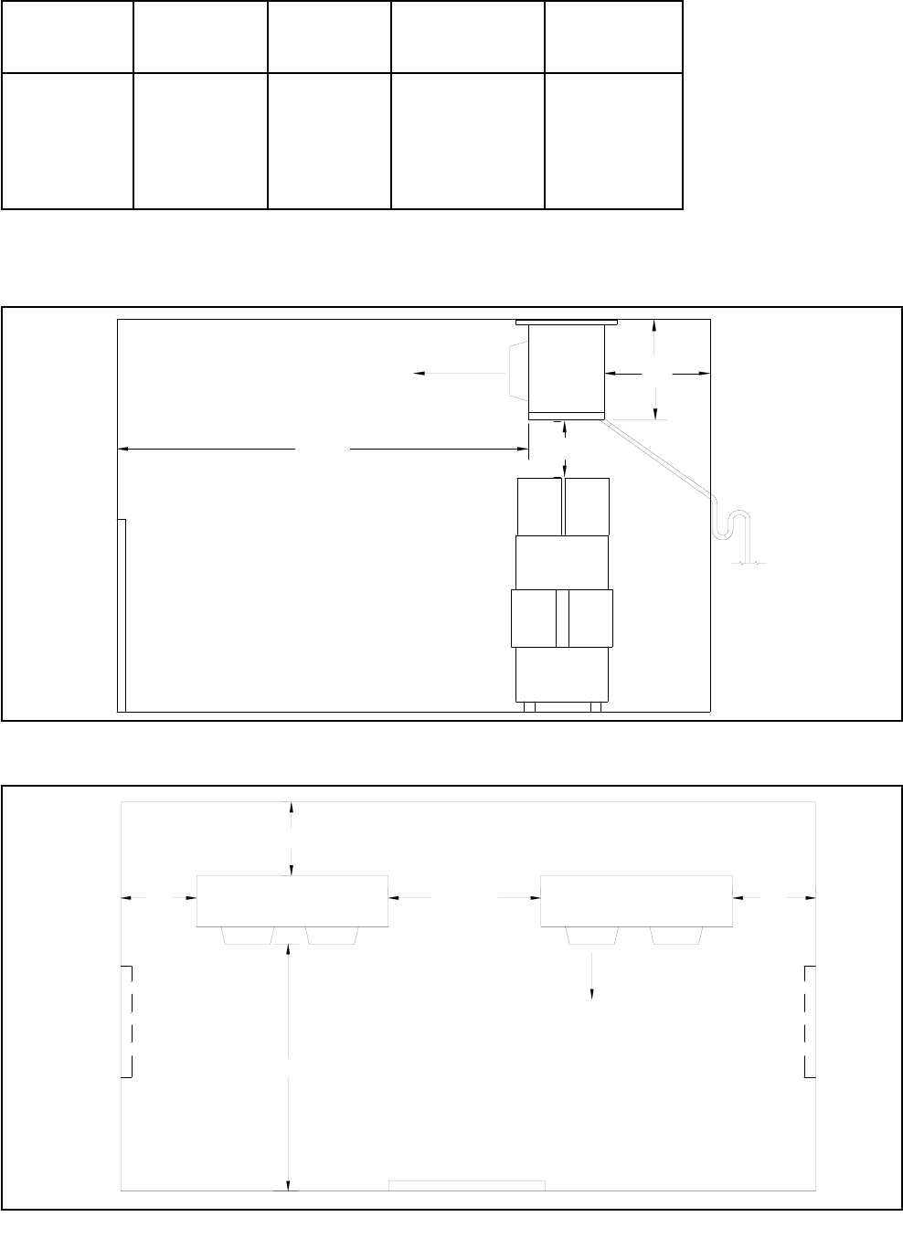
Condensing unit - Minimum clearances
Do not locate condensing units so that they are bordered on three or more sides by tall
obstructions. Condensing units should be positioned so that the airflow through the con-
denser is the same as the prevailing winds. If strong variable winds are common, a wind
deflector should be used on the discharge side of the unit. Be certain that there is adequate
room around the unit for regular inspection and service. For multiple unit sites, do not locate
units where the air discharge from one condensing unit will enter into the air intake of other
units.
Roof mounted condensing units should be located above supporting walls, over storage
areas or spaces not sensitive to noise or vibration. They must be adequately supported.
Pad mounted condensing units should be installed a minimum of 4 inches above ground
level, away from windows, doors and other areas where noise may be a problem. All units
must be level when mounted.
Minimum
HP Dimensions (in)
ABC
1/2 - 2 60 24 36
3 - 6 72 24 36
8 - 15 72 30 48
20 - 40 48 48 48
C
B
B
A
CONDENSING UNIT
PLAN VIEW
Discharge air Intake air
2
Table 1
Drawing 1

3
CONDENSING UNIT INSTALLATION (continued.)
Condensing units with spring mounted compressors are shipped with retainers under the
compressor feet to prevent damage during shipment. For Copeland H and K body
compressors, remove the retainers and loosen the mounting nut to allow 1/16” clearance
between the nut and rubber spacer. For 3HP and larger units, the mounting nuts must be
removed to insert the rubber spacer. Insert the rubber spacer over the mounting studs,
replace the nut and tighten to within 1/16” of the spacer. DO NOT
TIGHTEN THE NUTS
AGAINST THE SPACER OR FOOT.
Units with iso-pad mounted compressors are shipped with the mounting nuts tight. These
should be checked to make certain that they have not loosened during shipment.
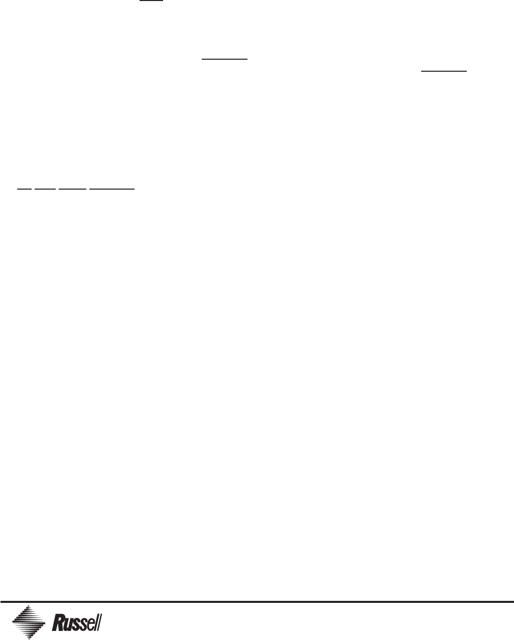
LOCATING AND MOUNTING UNIT COOLERS
Determine the best location for the unit in the walk-in cooler or freezer. Consider the air pat-
tern required to cover the entire space. For High Sierra Systems with two unit coolers, locate
the unit coolers so that the piping runs from the suction and liquid line tees are equal in size
and length.
Do not restrict the inlet or outlet air stream. Place the unit cooler as far as possible from
any door openings. Direct the discharge air stream towards the door whenever possible.
This will help to prevent warm, moist air from being drawn into the coil (Drawings 2, 3 and
Table 2). Adequate clearances should be maintained around the unit cooler to allow for
proper airflow through the unit and for regular maintenance and service to be preformed.
For all Hot Gas defrost unit coolers, ensure that the drain pan is in contact with the Hot Gas
drain pan loop after installation. If the drain pan is removed for any reason, verify
that it has
physical contact with the defrost loop when replaced.
The drain line should be pitched a minimum of 4" per foot to allow proper drainage and
should exit the room as quickly as possible. Do not reduce the drain line size. Do not locate
line bends, elbows or drain traps within the refrigerated space. All drain lines must be
trapped outside of the enclosure where the temperature is never below 35 degrees. Drain
lines should run to an open drain and should never be attached directly to a sewage or waste
line. Drain lines must be protected from possible freezing. Freezer units must have copper
drain lines that are heated and insulated.
Remove all packaging materials before lifting the unit into position. Be certain that the unit is
not sitting on the drain fitting or refrigerant connections. All-Temp units should be hung using
5/16" minimum diameter, stainless steel support rods or fasteners at all hanging slots. Use
minimum 3/8" hanger rods for Inter-Temp and Ultra-Temp models.
Tighten all fasteners securely. All units must be positioned level, flush with the ceiling and all
gaps must be properly caulked. Allow minimum clearances on all sides of the unit cooler(s) as
indicated in Table 2 (next page).
Recommended Minimum Dimensions
Table 2 Dimensions are in inches.
* Absolute minimum Distance
** 15’ is adequate clearance for these models
12"
min.
Slope Drain
line 4" per foot
and trap.
Air
5 x H*
obstruction
free area
door
H*
Drawing 2
Unit cooler Air intake* Side Air discharge Unit to
Height clearance clearance clearance floor
H 1 x H 1 x H 2 x H 5 x H
15 15 15 30 75
19 19 19 38 95
25 25 25 50 125
32 32 32 64 160
50 50 50 100 180**
Door
H* H*
H*
5 x H*
Back Wall
Front Wall
Alternate
Door
Location
Alternate
Door
Location
Air
Keep air discharge
area free from
obstruction
2 x H*
Discharge
Drawing 3
4

5
FIELD WIRING
All field wiring must be done in compliance with local and national electrical codes. Use only
properly sized Copper conductors. A system wiring diagram is located inside the condensing
unit control box. Wire components as indicated on the diagram. The equipment nameplates are
marked with electrical characteristics. All field wiring should enter the equipment through
electrical conduit bushings. Note: All units must be grounded.
Before applying power to the units, check all connections to ensure they have not come loose
during shipment. Be
certain that the power is disconnected before tightening any electrical
connections. Disconnect switches and evaporator branch circuit protection are supplied by the
equipment installer and must conform to governing electrical codes. Air defrost systems are
wired so that the evaporator fans run continuously. For electric defrost and High Sierra systems,
the evaporator fans are cycled off during the defrost and re-cooling period.
Electric defrost unit coolers are supplied with a temperature sensing defrost termination switch
that will end the defrost at a preset coil temperature. (Recommended time clock settings for
electric defrost are 2 defrosts per day, with a twenty minute fail safe setting. Adjust according to
job site conditions. Fewest possible defrost
s for the shortest possible duration are desirable.)
A high limit control is provided to prevent overheating if there is a component failure. A fan delay
control is installed to allow the water condensate on the fins to freeze before the evaporator fan
motors start. A pumpdown cycle is mandatory for all systems.
For both Sierra and High Sierra systems, a liquid line solenoid is factory installed and wired to
each unit cooler terminal board (multiple evap systems receive multiple solenoid valves). Follow
the system wiring diagram (provided in the condensing unit). Connection to
TB1-44 must be
made to assure proper pumpdown function. The room thermostat is mounted on the unit cooler
for single evaporator systems and supplied loose for multiple evaporator systems. Follow the
system wiring diagram supplied in the condensing unit.
REFRIGERANT PIPING
Condensing units and unit coolers are thoroughly cleaned and dehydrated at the factory. Use
only ACR (refrigeration grade) tubing that is dehydrated and sealed. Only use WROT Copper
fittings, cast fittings are a source of refrigerant leaks. All liquid and suction elbows must be long
radius types for minimum pressure drop. Refrigerant lines must be properly supported to
prevent vibration and breakage. Tube clamps should have a gasketed liner to prevent abrasion of
the tubing. Sierra and High Sierra must not exceed more then a 100’ refrigerant line run.
Install all piping and components in accordance with local and national codes. Make refrigerant
connections by using only hard or Silver bearing solder such as Silfos, Stay-Silv or higher Silver
content brazing material. Slowly purge dry nitrogen through the tubing while brazing to prevent
the formation of Copper oxide scale.
LIQUID LINE
Refer to the current ASHRAE Refrigeration Systems and Applications Handbook for assistance
in determining appropriate liquid line sizes.
Horizontal and vertical liquid lines are normally the same diameter. However, pressure loss due
to vertical lift may lead to flash gas that can inhibit proper TXV (and system) performance if not
properly accounted for. Under sizing the liquid line can result in flash gas while over sizing the
liquid line will unnecessarily increase the system charge requirement.
Sierra and High Sierra condensing units include Russell’s patented finned receiver
®
, which is
integrated into the air-cooled condenser. This finned receiver
®
also acts as an efficient liquid
sub-cooler. An additional liquid to suction heat exchanger is not normally required. The liquid
line must be insulated to obtain the maximum benefits of the subcooled liquid.

SUCTION LINES
The suction line and it’s components must be carefully selected and installed. The suction line
must be sized to maintain a balance of adequate refrigerant velocity, to allow for good oil
return, and a low pressure drop that will prevent excessive capacity loss. The optimal line
size will result in a reasonable refrigerant velocity and a minimum pressure drop. Total suction
line pressure loss should not exceed 2
o
F equivalent loss. For best system performance, the
suction line should be insulated.
Suction line risers should be no larger in diameter than the horizontal pipe run. Refer to the
current ASHRAE Refrigeration Systems and Applications Handbook for correct suction line
and riser sizing. Horizontal suction line runs should slope in the direction of flow, 1 inch per
ten feet of length. All suction lines should be insulated as soon as they exit the refrigerated
space. Install a 1/4-inch schrader fitting near the evaporator outlet to assist in accurate super-
heat readings. All suction line risers should be trapped to facilitate oil return. Additional
P-Traps are required for every 15 feet of elevation. Oil traps should be the same diameter as
the suction line riser that it attaches to.
MULTIPLE EVAPORATOR PIPING
High Sierra systems involving multiple evaporators require that piping runs be of equal length
to each evaporator. The line runs must be of equivelent length from the bull-head tees to
each unit cooler. This will ensure proper distributon of hot gas to each unit cooler during the
defrost cycle. Reference the drawing below for further clarification.
60c.o.
Sight
Glass
Defrost
Termination
Set: 250c.i.
Relief
Valve
Valve
200c.o.
Set: 90c.i.
Fan Cyle
Control
Check
Valve
Suction Filter
Liquid
Valve
Shutoff
Compressor
Condensing Unit
Reversing
Condenser Coil
TXV
Power
Supply
Insulation
Evaporator
Evaporator
TXV
Drain Pan Circuit
Valves
Check
Sol. Valve
Liquid
Check Valve
Drain Pan Circuit
Check
Valves
Check Valve
Liquid
Sol. Valve
TXV
Bi-Flow
Liquid Filter
Size For Total System Capacity
Size for one evaporator capacity.
Must be equal length or equivelent pressure drop.
Tee must be oriented to split hot gas defrost.
6
LEAK TESTING
After all refrigerant connections are made, add the proper system refrigerant until the pressure
is 25 to 35 PSI. Then pressurize with dry nitrogen up to 120 PSI. Always use a pressure
reducing regulator. Wait 30 minutes for the refrigerant to reach all parts of the system. Use an
electronic leak detector to inspect all connections and system components. Repair any leaks
that are found and re-check until all leaks are eliminated. Leave the system pressurized over
night. Once the system is tight, it must be evacuated before charging.

7
EVACUATION
Proper installation procedures must include a deep evacuation of the system. A clean/dry
system is essential when charging refrigerant. Open all service valves. The high vacuum
method is the most effective procedure for assuring a clean and dry system. It requires the
use of a two-stage high vacuum pump, an electronic high-vacuum gauge and 3/8" minimum
OD copper tubing. Use a high vacuum sealant on all lines and connections. Clean and dry
DEEP
VACUUM OIL is essential for proper system evacuation.
This step is required
FOR SIERRA/HIGH SIERRA SYSTEMS:
Evacuation access fitting:
AREA 1: From the compressor service valve (including the compressor head)
through the condenser up to the liquid line module; Connecting to the port on
the compressor discharge valve gets this area.
AREA 2: From the liquid line module to the liquid line solenoid; connecting to
the liquid line “King” valve port gets this area on Sierra system. The connection
will not properly evacuate area 1, above, since evacuation would have to be
pulled through the check valve in the module, which will have about 1 PSI
restriction. However, on High Sierra systems a pressure tap at the connection
for the terminator pressure control evacuates the liquid line since this connection
is downstream of the module.
AREA 3 : From the liquid line solenoid to the compressor (including the crankcase)
connecting to the suction service port gets this area.
The need for this clarification has arisen from the fact that some systems have
experienced high head pressure because non-condensables were left in the system
when these procedures were not followed.
All systems - continued
Connect the vacuum lines to both the high and low-pressure sides of the system. Run the
vacuum pump until the gauge reaches 500 microns for newly installed systems. With the
pump still running, shut off the high vacuum line valve. The vacuum gauge should not exceed
(1500 microns or less ) after two minutes once the pump is closed off, though the pressure
will increase slightly even on the most leak-free system. Open the compressor service valves
and pull a continuous vacuum for a minimum of 4 hours. Pulling the vacuum overnight is
highly recommended (mandatory for 5 HP systems and larger). Do not allow the system to
stand at high vacuum without the vacuum pump operating. Do not start the compressor while
the system is under a vacuum.
CHARGING
Both Sierra and High Sierra systems are designed to operate with minimum refrigerant
charge and minimum head pressures. - Low head pressures are normal at low ambient
conditions.
Make the charging line connection with a hose that is purged of air
, through a filter drier.
Break the vacuum with the proper system refrigerant. Charge liquid refrigerant into the high
side of the system. This should enable the system to operate. Add refrigerant charge as nec-
essary to achieve a clear sight glass
with the system close to normal operating condition,
whether it is winter or summer
. Ambient temperature is not relevant to the charging proce-
dure.
IMPORTANT! Sierra and High Sierra systems are critical charge systems.
Be careful, DO
NOT OVERCHARGE!

8
CHARGING
continuation...
Refrigerant can be added most rapidly by introducing liquid directly into the liquid line down
stream of the liquid line valve. Close the liquid line intermittently and add refrigerant directly
into the port on the side of the liquid line valve until the sight glass is clear.
NOTE: Some new refrigerants require liquid charging only.
Be extra diligent not to log liquid in the accumulator, if one is present in the system. An
accumulator is not recommended for Sierra or High Sierra systems. They can negatively
impact the charging procedure of these systems. Liquid build-up in the accumulator may
result from improper charging. Once in the accumulator the refrigerant returns very slowly.
Depending on how much is accumulated, how much frost is on the accumulator (frost acts
as an insulator so the refrigerant boils off slower), ambient temperature, etc..., this excess
refrigerant can cause significant problems.
START UP
Install gauges on the system to check both high and low pressures. Using the gauges, verify
that the low-pressure control is properly set (3 PSI cut out, 15 PSI cut in).
Pump down the system by closing the liquid line solenoid and the service valve to verify that
there is no objectionable increase in head pressure.
Be certain that the fan cycling control is properly adjusted. At the correct setting the cut-out
setting should be 30 PSI above the design suction pressure. The cut-in setting should be 30
PSI above the cut out pressure.
THIS STEP
IS REQUIRED FOR HIGH SIERRA ONLY
Move the high side gauge to the defrost termination schrader valve on the suction
line and start a defrost cycle. Verify that the defrost terminates at 250 PSI, adjust
the termination control if necessary. Set the time clock defrost fail-safe to
A MAXIMUM OF 10 MINUTES and an initial setting of 2 defrosts per day.
Check the evaporator superheat after the system has run long enough to reach a balanced
state. Low temperature systems normally operate most efficiently at a superheat settings that
range from 6 to 8 degrees at design room temperature. Medium temperature rooms normally
operate from 8 to 10 degree evaporator superheat. Adjust expansion valves only if necessary.
GENERAL MAINTENANCE
Disconnect all electrical power to the unit before inspecting or cleaning. Unit coolers and
condensing units should be checked periodically and cleaned of all dirt or grease accumulation.
Fan blades and guards may require more frequent cleaning. Remove debris from the
condenser coil using a brush or vacuum cleaner. All fan motors are life lubricated and do not
require periodic oiling. Do not use ammonia or other cleaning agents that are corrosive or
react with Copper or Aluminum.
If the liquid line filter is replaced High Sierra system, it must be replaced with a Bi-Flow filter
.

TYPICAL FIELD WIRING DIAGRAMS
SIERRA SYSTEMS
Air Defrost
Systems
Condensing unit
Condensing unit
Electric Defrost
Single unit cooler
1 phase motors
3 phase heaters
Condensing unit
Condensing unit
HIGH SIERRA COUNTER FLOW DEFROST
Single unit cooler
1 Phase motor(s)
Condensing unit
— —
Field wiring
TB1 - Terminal block # 1
TB2 - Terminal block # 2
C6 - Heater contactor
LLS - Liquid line solenoid
EF - Evaporator fan motor(s)
T’stat - Room thermostat
DT - Defrost Termination
FD - Fan Delay Control
Condensing unit
2 unit coolers
1 Phase motors
Legend (all diagrams)
*See page 5 for wiring instructions. 9
Electric Defrost
Two unit coolers
1 phase motors
1 phase heaters
Electric Defrost
Single unit cooler
1 phase motors
1 phase heaters

10
HIGH SIERRA - Sequence of operation.
Refrigeration cycle
The High Sierra counter flow defrost system is unique in design. It operates like most conventional
systems during the refrigeration cycle. As cooling is called for, the compressor,
condenser fan(s), evaporator fans and liquid line solenoid valve are all energized.
Refrigerant vapor exits the compressor discharge port, moves through the High Sierra reversing
valve and into the air-cooled condenser. As ambient air flows through the condenser, the refriger-
ant vapor gives up it's heat, becomes liquid and moves through the patented Sierra Finned
Receiver
®
and liquid sub-cooler.
The sub-cooled liquid refrigerant exits the sub-cooler, passing through the High Sierra check valve
/ TXV valve assembly, leaving the condensing unit via a bi-flow liquid filter.
The liquid refrigerant enters the evaporator, flowing through a factory mounted solenoid valve. It
passes through the expansion valve to be boiled off in the coil, providing cooling for the box. The
vaporized refrigerant returns through the suction line, the reversing valve and suction filter into the
compressor suction port.
As with any normal pump-down system, when the room temperature satisfies the thermostat, it de-
energizes the liquid line solenoid, causing the system to pump down and cycle off.
Counter flow defrost cycle
The defrost timer initiates the counter flow defrost cycle. The number of defrost cycles is set by the
installer. (The recommended frequency is one to two defrosts per day with the fail safe override set
at 10 minutes. A
normal defrost cycle lasts from 3 to 7 minutes.)
Upon the signal from the defrost timer, the reversing valve switches modes and the
evaporator fan motors are turned off. The liquid line solenoid remains energized.
The direction of refrigerant flow is now reversed, as are the functions of the evaporator and con-
denser. The reversing valve diverts the compressor discharge through, what was formerly the suc-
tion line, back towards the evaporator. A suction line check valve, (factory mounted), routes the
discharge gas through the evaporator drain pan circuit and into the coil tubes, thus providing the
heat source for the counter flow defrost.
The evaporator, now acting as the condenser, converts the discharge gas into liquid, releasing
large amounts of heat, defrosting the coil(s) very quickly.
The liquid refrigerant then exits the coil through the distributor, and the factory mounted TXV
bypass check valve. It moves through the liquid line, the bi-flow liquid filter, through the condenser
TX valve and into the system condenser (now acting as the evaporator). The liquid refrigerant is
then boiled off and returned to the compressor as suction gas, passing first through the reversing
valve and suction filter.
The defrost cycle is ended when the system pressure reaches the termination point at the defrost
control (located in the condensing unit). The inst
aller must verify that the coil clears completely of
all frost and ice. If the defrost cycle terminates before all frost has been completely removed from
the coil, the defrost termination pressure control setting may be increased incrementally until the
coil defrosts properly (maximum setting 300 psi). The recommended defrost termination setting is
250 psi with a 50 psi differential.

Diagram 5
Diagram 4
11
Counterflow defrost cycle - continued
After the refrigeration cycle resumes, the evaporator fan motors remain off during the cool
down period (never less than two minutes). This allows all condensate to drain before the
fan motors are energized, thus preventing water from blowing off the coil and into the room.
Notes:
1. The condensing unit pressure relief valve is provided to regulate potential excessive pres-
sures that may develop in the liquid line during extended shut down periods. It does not come
into play during the refrigeration or defrost cycles.
2. The condensing unit TX valve is factory set and should not be field adjusted.
3. The evaporator fan delay control is located in the condensing unit
control panel.
High Sierra Piping

Comp. Cond. Unit Rev. Valve Strainer Cond. Unit Liquid Filter Low Pres. High Pres. Fan Cycle
Type Model No. PART# PART# TXV (c.u.) PART# 230V Motor Blade Control Control Control
RHH100L44 21012 123277001 SBFSE-AA-Z 104471048 102540004 119103001 24464232 204464208 204464002
RHH165L44 21012 123277001 SBFSE-A-Z 104471049 102540004 119103001 24464232 204464208 204464002
RHH215L44 21012 123277001 SBFSE-B-Z 104471049 102540004 119103001 24464232 204464208 204464002
RHH315L44 21012 123277001 SBFSE-C-Z 104471046 102540004 119103001 24464232 204464208 204464002
RHS075L44 21012 123277001 SBFSE-AA-Z 104471048 102540004 119103001 24464232 204464208 204464002
RHS100L44 21012 123277001 SBFSE-A-Z 104471048 102540004 119103001 24464232 204464208 204464002
RHS150L44 21012 123277001 SBFSE-A-Z 104471049 102540004 119103001 24464232 204464208 204464002
RHS200L44 21012 123277001 SBFSE-B-Z 104471049 102540004 119103001 24464232 204464208 204464002
RHS250L44 21012 123277001 SBFSE-B-Z 104471046 102540004 119103001 24464232 204464208 204464002
RHS300L44 21012 123277001 SBFSE-C-Z 104471046 102540004 119103001 24464232 204464208 204464002
RHD300L44 16506 123277002 SBFSE-C-Z 104471046 201006007 213266000 24464232 204464208 204464002
RHD400L44 16506 123277002 EBSSE-6-Z 104471047 201006007 213266000 24464232 204464208 204464002
RHD500L44 16506 123277002 EBSSE-6-Z 104471047 201006007 213266000 24464232 204464208 204464002
RHO200L44 21012 123277001 SBFSE-A-Z 104471049 201006007 213266000 24464232 204464208 204464002
RHO250L44 21012 123277001 SBFSE-B-Z 104471046 201006007 213266000 24464232 204464208 204464002
RHO300L44 21012 123277001 SBFSE-B-Z 104471046 201006007 213266000 24464232 204464208 204464002
RHO301L44 21012 123277001 SBFSE-C-Z 104471046 201006007 213266000 24464232 204464208 204464002
RHO400L44 21012 123277001 SBFSE-C-Z 104471047 201006007 213266000 24464232 204464208 204464002
RHO500L44 16506 123277002 EBSSE-6-Z 104471047 201006007 213266000 24464232 204464208 204464002
RHO600L44 16506 123277002 EBSSE-6-Z 104471047 201006007 213266000 24464232 204464208 204464002
DHD5L44 21054 123277003 EBSSE-6-Z 104471047 205051004 213266000 204464041 Hi/Lo Combo 204464002
DHD6L44 21054 123277003 EBSSE-7 1/2-Z 104471047 205051004 213266000 204464041 Hi/Lo Combo 204464002
DHD8L44 21054 123277003 EBSSE-10-Z 104471066 205051004 213266000 204464041 Hi/Lo Combo 204464002
DHD9L44 21054 123277003 EBSSE-10-Z 104471066 205051004 213266000 204464041 Hi/Lo Combo 204464002
DHD10L44 21000 123277004 EBSSE-13-Z 104471066 205051004 213266000 204464041 Hi/Lo Combo 204464002
DHD12L44 21000 123277004 EBSSE-13-Z 104471066 205051004 213266000 204464041 Hi/Lo Combo 204464002
DHD15L44 21000 123277004 EBSSE-13-Z 104471193 205051004 213266000 204464041 Hi/Lo Combo 204464002
DHO6L44 16506 123277002 EBSSE-6-Z 104471066 205051004 213266000 204464041 Hi/Lo Combo 204464002
DHO8L44 21054 123277003 EBSSE-6-Z 104471066 205051004 213266000 204464041 Hi/Lo Combo 204464002
DHO10L44 21054 123277003 EBSSE-10-Z 104471066 205051004 213266000 204464041 Hi/Lo Combo 204464002
DHO13L44 21054 123277003 EBSSE-10-Z 104471066 205051004 213266000 204464041 Hi/Lo Combo 204464002
VHD15L44 21049 123277005 OSE-21-Z
104471021
†
110204000 210385000
204464041 Hi/Lo Combo 204464002
VHD22L44 21049 123277005 OSE-21-Z
104471021
†
110204000 210385000
204464041 Hi/Lo Combo 204464002
VHD27L44 21055 123277005 OSE-30-Z
104471021
†
110204000 210385000
204464041 Hi/Lo Combo 204464002
VHD30L44 21055 123277005 OSE-30-Z
104471021
†
110204000 210385000
204464041 Hi/Lo Combo 204464002
VHD44L44 21055 123277005 OSE-45-Z
104471022
†
110204000 210385000
204464041 Hi/Lo Combo 204464002
VHD54L44 21056 Contact (2) OSE-30-Z
104471022
†
110204000 210385000
204464041 Hi/Lo Combo 204464002
VHD60L44 21056 Factory (2) OSE-30-Z
104471022
†
110204000 210385000
204464041 Hi/Lo Combo 204464002
* Parts may vary based upon specific operating conditions.
† V-Series filter is not Bi-Flow Design. Part number is for replaceable core filter (shell only). Core Part# 14471034 (may require more than one core)
Discus
Discus
Scroll
Discus
Scroll
Typical High Sierra replacement parts- Low Temp. Models*
Hermetic
Semi-Hermetic
Condenser
Russell Part # Description
21065 Rebuild kit for Russell Part#16506
21066 Rebuild kit for Russell Part#21054
21067 Rebuild kit for Russell Part#21000
21068 Rebuild kit for Russell Part#21056
21070 O-Ring Kit for Russell Part# 21012
21072 O-Ring Kit for Russell Part#16506
21073 O-Ring Kit for Russell Part# 21054
21074 O-Ring Kit for Russell Part# 21000
21075 O-Ring Kit for Russell Part# 21049
21076 O-Ring Kit for Russell Part# 21055
21077 O-Ring Kit for Russell Part# 21056
21079 PILOT ASSY/MANIFOLD for Russell Part# 21054
21080 PILOT ASSY/MANIFOLD for Russell Part# 21000
21063 PILOT ASSY/MANIFOLD for Russell Part# 21049
204464020 HIGH SIERRA Defrost Termination Control
104799015 HIGH SIERRA Evap Fan Delay Control
204464004 HIGH SIERRA Condensing Unit Fan Cycle Control
104799020 HIGH SIERRA RELAYS R1 & R2 (Same number for each)
104799010 HIGH SIERRA Defrost Timer
12

Comp. Model Reversing Rev. Valve Cond. Unit Repl. Core Low Pres. High Pres.
Type Number Valve Strainer TXV Liquid Filter 230V Motor Blade Control Control
RHH075H22 21012 123277001 SBFVE-AA-C 104471048 102540004 119103001 24464232 204464208
RHH100H22 21012 123277001 SBFVE-A-C 104471048 102540004 119103001 24464232 204464208
RHH151H22 21012 123277001 SBFVE-A-C 104471049 102540004 119103001 24464232 204464208
RHH201H22 21012 123277001 SBFVE-B-C 104471049 102540004 119103001 24464232 204464208
RHH251H22 21012 123277001 SBFVE-B-C 104471046 102540004 119103001 24464232 204464208
RHH301H22 21012 123277001 SBFVE-C-C 104471046 102540004 119103001 24464232 204464208
RHH401H22 21012 123277001 SBFVE-C-C 104471047 205051004 213266000 24464232 204464208
RHH500H22 21012 123277001 SBFVE-C-C 104471047 205051004 213266000 24464232 204464208
RHH050M44 21012 123277001 SBFSE-A-C 104471048 102540004 119103001 24464232 204464208
RHH075M44 21012 123277001 SBFSE-A-C 104471048 102540004 119103001 24464232 204464208
RHH101M44 21012 123277001 SBFSE-B-C 104471048 102540004 119103001 24464232 204464208
RHH150M44 21012 123277001 SBFSE-B-C 104471049 102540004 119103001 24464232 204464208
RHH201M44 21012 123277001 SBFSE-C-C 104471049 102540004 119103001 24464232 204464208
RHH300M44 21012 123277001 SBFSE-C-C 104471046 102540004 119103001 24464232 204464208
RHH400M44 16506 123277002 EBSSE-6-C 104471047 205051004 213266000 24464232 204464208
RHS050H22 21012 123277001 SBFVE-AA-C 104471048 102540004 119103001 24464232 204464208
RHS075H22 21012 123277001 SBFVE-AA-C 104471048 102540004 119103001 24464232 204464208
RHS100H22 21012 123277001 SBFVE-A-C 104471048 102540004 119103001 24464232 204464208
RHS150H22 21012 123277001 SBFVE-A-C 104471049 102540004 119103001 24464232 204464208
RHS200H22 21012 123277001 SBFVE-B-C 104471049 102540004 119103001 24464232 204464208
RHS300H22 21012 123277001 SBFVE-C-C 104471046 102540004 119103001 24464232 204464208
RHS400H22 21012 123277001 SBFVE-C-C 104471047 205051004 213266000 24464232 204464208
RHS050M44 21012 123277001 SBFSE-A-C 104471048 102540004 119103001 24464232 204464208
RHS100M44 21012 123277001 SBFSE-A-C 104471048 102540004 119103001 24464232 204464208
RHS200M44 21012 123277001 SBFSE-B-C 104471049 102540004 119103001 24464232 204464208
RHS300M44 21012 123277001 SBFSE-C-C 104471046 102540004 119103001 24464232 204464208
RHS400M44 16506 123277002 EBSSE-6-C 104471047 205051004 213266000 24464232 204464208
RHO200M44 21012 123277001 SBFSE-C-C 104471049 205051004 213266000 24464232 204464208
RHO250M44 21012 123277001 SBFSE-C-C 104471046 205051004 213266000 24464232 204464208
RHO300M44 21012 123277001 SBFSE-C-C 104471046 205051004 213266000 24464232 204464208
RHO301M44 16506 123277002 EBSSE-6-C 104471046 205051004 213266000 24464232 204464208
RHO400M44 16506 123277002 EBSSE-6-C 104471047 205051004 213266000 24464232 204464208
RHO500M44 16506 123277002 EBSSE-6-C 104471047 205051004 213266000 24464232 204464208
RHO600M44 21054 123277003 EBSSE-6-C 104471047 205051004 213266000 24464232 204464208
RHO650M44 21000 123277004 EBSSE-7 1/2-C 104471066 205051004 213266000 24464232 204464208
* Parts selection may vary based upon specific operating conditions.
Medium Temp models are only available for warm ambient locations.
Typical High Sierra replacement parts - R-Series Medium Temp. Models*
Hermetic
Semi-Hermetic
Scroll
Condenser
13

Comp. Model Reversing Rev. Valve Cond. Unit
Bi-Flo
†
Low Pres. High Pres. Fan Cycle
Type Number Valve Strainer TXV Liquid Filter 230V Motor Blade Control Control Control
DHD5H22 16506 123277002 EBSVE-8-C 104471066 205051004 213266000 204464041 Hi/Lo Combo 204464002
DHD7H22 21054 123277003 EBSVE-11-C 104471066 205051004 213266000 204464041 Hi/Lo Combo 204464002
DHD8H22 21054 123277003 EBSVE-11-C 104471066 205051004 213266000 204464041 Hi/Lo Combo 204464002
DHD10H22 21054 123277003 EBSVE-15-C 104471193 205051004 213266000 204464041 Hi/Lo Combo 204464002
DHD12H22 21000 123277004 EBSVE-15-C 104471193 205051004 213266000 204464041 Hi/Lo Combo 204464002
DHD5M44 21054 123277003 EBSSE-10-C 104471066 205051004 213266000 204464041 Hi/Lo Combo 204464002
DHD6M44 21054 123277003 EBSSE-10-C 104471066 205051004 213266000 204464041 Hi/Lo Combo 204464002
DHD7M44 21054 123277003 EBSSE-10-C 104471066 205051004 213266000 204464041 Hi/Lo Combo 204464002
DHD8M44 21000 123277004 EBSSE-13-C 104471066 205051004 213266000 204464041 Hi/Lo Combo 204464002
DHD10M44 21000 123277004 EBSSE-13-C 104471193 205051004 213266000 204464041 Hi/Lo Combo 204464002
DHD12M44 21049 123277005 EBSSE-13-C 104471193 205051004 213266000 204464041 Hi/Lo Combo 204464002
DHO6M44 16506 123277002 EBSSE-7 1/2-C 104471047 205051004 213266000 204464041 Hi/Lo Combo 204464002
DHO7M44 21054 123277003 EBSSE-10-C 104471066 205051004 213266000 204464041 Hi/Lo Combo 204464002
DHO8M44 21054 123277003 EBSSE-10-C 104471066 205051004 213266000 204464041 Hi/Lo Combo 204464002
DHO10M44 21000 123277004 EBSSE-13-C 104471193 205051004 213266000 204464041 Hi/Lo Combo 204464002
DHO13M44 21000 123277004 EBSSE-13-C 104471193 205051004 213266000 204464041 Hi/Lo Combo 204464002
VHD15H22 21000 123277004 EBSVE-20-C
104471021
†
110204000 210385000
204464041 Hi/Lo Combo 204464002
VHD20H22 21049 123277005 EBSVE-20-C
104471021
†
110204000 210385000
204464041 Hi/Lo Combo 204464002
VHD25H22 21049 123277005 OVE-30-C
104471021
†
110204000 210385000
204464041 Hi/Lo Combo 204464002
VHD30H22 21049 123277005 OVE-30-C
104471022
†
110204000 210385000
204464041 Hi/Lo Combo 204464002
VHD35H22 21055 123277005 OVE-40-C
104471031
†
110204000 210385000
204464041 Hi/Lo Combo 204464002
VHD40H22 21055 123277005 OVE-40-C
104471031
†
110204000 210385000
204464041 Hi/Lo Combo 204464002
VHD50H22 21055 123277005 (2) OVE-30-C
104471031
†
110204000 210385000
204464041 Hi/Lo Combo 204464002
VHD60H22 21056 Contact Factory (2) OVE-30-C
104471032
†
110204000 210385000
204464041 Hi/Lo Combo 204464002
VHD70H22 21056 Contact Factory (2) OVE-40-C
104471033
†
110204000 210385000
204464041 Hi/Lo Combo 204464002
VHD80H22 21057 Contact Factory (2) OVE-40-C
104471033
†
110204000 210385000
204464041 Hi/Lo Combo 204464002
VHD15M44 21049 123277005 OSE-21-C
104471021
†
110204000 210385000
204464041 Hi/Lo Combo 204464002
VHD20M44 21049 123277005 OSE-21-C
104471021
†
110204000 210385000
204464041 Hi/Lo Combo 204464002
VHD25M44 21055 123277005 OSE-30-C
104471021
†
110204000 210385000
204464041 Hi/Lo Combo 204464002
VHD30M44 21055 123277005 OSE-30-C
104471022
†
110204000 210385000
204464041 Hi/Lo Combo 204464002
VHD35M44 21055 123277005 OSE-30-C
104471031
†
110204000 210385000
204464041 Hi/Lo Combo 204464002
VHD40M44 21056 Contact Factory OSE-35-C
104471031
†
110204000 210385000
204464041 Hi/Lo Combo 204464002
VHD50M44 21056 Contact Factory OSE-45-C
104471031
†
110204000 210385000
204464041 Hi/Lo Combo 204464002
VHD60M44 21056 Contact Factory OSE-45-C
104471032
†
110204000 210385000
204464041 Hi/Lo Combo 204464002
VHD70M44 21057 Contact Factory (2) OSE-30-C
104471033
†
110204000 210385000
204464041 Hi/Lo Combo 204464002
VHD80M44 21057 Contact Factory (2) OSE-35-C
104471033
†
110204000 210385000
204464041 Hi/Lo Combo 204464002
* Parts selection may vary based upon specific operating conditions.
† V-Series filter is not Bi-Flow Design. Part number is for replaceable core filter (shell only). Core Part# 14471034 (may require more than one core)
Medium Temp models are only available for warm ambient locations.
Typical High Sierra replacement parts- D-Series and V-Series Medium Temp. Models*
Discus
Scroll
Discus
Condenser
14

MODEL NUMBER ALL-TEMP²B - MODELS AA, AE (AFTER APRIL, 2004 ) PART NUM.
MOTOR, SHADED POLE, 1/20 HP, 1550 RPM, 115 V. 102540003
ALL MODELS MOTOR, SHADED POLE, 1/20 HP, 1550 RPM, 208-230 V. 102540004
MOTOR, SHADED POLE, 1/20 HP, 1550 RPM, 460 V. 102540005
ALL MODELS FAN GUARD, PLASTIC, BLACK, 12" 119647000
ALL MODELS FAN GUARD, WIRE, EPOXY COATED, BLACK, 12" 201006011
ALL MODELS MOTOR MOUNT 21062000
MOTOR, PSC, 1/20 HP, 1550 RPM, 115 V., (3 MFD CAPACITOR NOT INCL.) 108178001
ALL MODELS (OPTIONAL) MOTOR, PSC, 1/20 HP, 1550 RPM, 230 V., (2 MFD CAPACITOR NOT INCL.) 108178002
CAPACITOR, 3 MFD, FOR 1/20 115 V. PSC MOTOR 202163010
CAPACITOR, 2 MFD, FOR 1/20 230 V. PSC MOTOR 202163009
ALL "AE" MODELS DEFROST CONTROL, DEFROST TERMINATION, (TIMER RESET) 2 WIRE 103079010
ALL "AE" MODELS DEFROST CONTROL, FAN DELAY, 2 WIRE 103079009
1 - 6 FAN AE MODELS HEATER SAFETY SWITCH, 2 WIRE 103079003
AE14-37B, AE16-36B, DEFROST HEATER, CORE, 500 WATTS, 26-1/4" LENGTH, 208-230/460 V. 206240006
AE16-41B, AE16-46B DEFROST HEATER, DRAIN PAN, 500 WATTS, 21" LENGTH, 208-230/460 V. 200172042
AE24-72B, AE24-85B, DEFROST HEATER, CORE, 1000 WATTS, 44-1/4" LENGTH, 208-230/460 V. 206240008
AE26-92B DEFROST HEATER, DRAIN PAN, 1000 WATTS, 39" LENGTH, 208-230/460 V. 200172044
AE26-60B, AE26-75B DEFROST HEATER, CORE, 800 WATTS, 40-1/4" LENGTH, 208-230/460 V. 206240007
DEFROST HEATER, DRAIN PAN, 800 WATTS, 35" LENGTH, 208-230/460 V. 200172043
AE34-105B, AE36-120B, DEFROST HEATER, CORE, 1500 WATTS, 62-1/4" LENGTH, 208-230/460 V. 206240009
AE36-140B DEFROST HEATER, DRAIN PAN, 1500 WATTS, 57" LENGTH, 208-230/460 V. 200172045
AE44-140B, AE46-164B, DEFROST HEATER, CORE, 2000 WATTS, 80-1/4" LENGTH, 208-230/460 V. 206240010
AE46-185B DEFROST HEATER, DRAIN PAN, 2000 WATTS, 75" LENGTH, 208-230/460 V. 200172046
AE54-180B, AE56-210B DEFROST HEATER, CORE, 2500 WATTS, 97-3/4" LENGTH, 208-230 V. 206240011
DEFROST HEATER, DRAIN PAN, 2500 WATTS, 93" LENGTH, 208-230/460 V. 200172047
AE64-215B, AE66-245B, DEFROST HEATER, CORE, 3000 WATTS, 115-3/4" LENGTH, 208-230/460 V. 206240012
AE66-280B DEFROST HEATER, DRAIN PAN, 3000 WATTS, 111" LENGTH, 208-230/460 V. 200172048
1 FAN AA, & AE MODELS VENTURI, 20" LENGTH 8519104
AA28-76B, -97B, -122B,
AA26-70B, -87B, AE26-60B, VENTURI, 34" LENGTH 8519241
AE26-75B
AA28-106B, -134B, AA26-115B VENTURI, 38" LENGTH 8519242
AE26-92B, AE24-85B
3 FAN AA & AE MODELS VENTURI, 56" LENGTH 8519243
4 FAN AA & AE MODELS* VENTURI, 74" LENGTH 8519244
5 FAN AA & AE MODELS* VENTURI, 92" LENGTH 8519245
6 FAN AA & AE MODELS* VENTURI, 110" LENGTH 8519246
1 FAN AA, & AE MODELS DRAIN PAN, 27" LENGTH 8519592
AA28-76B, -97B, -122B,
AA26-70B, -87B, AE26-60B, DRAIN PAN, 41" LENGTH 8519593
AE26-75B
AA28-106B, -134B, AA26-115B DRAIN PAN, 45" LENGTH 8519594
AE26-92B, AE24-85B
3 FAN AA & AE MODELS DRAIN PAN, 63" LENGTH 8519595
4 FAN AA & AE MODELS* DRAIN PAN, 81" LENGTH 8519596
5 FAN AA & AE MODELS* DRAIN PAN, 99" LENGTH 8519597
6 FAN AA & AE MODELS* DRAIN PAN, 117" LENGTH 8519598
SHORT
HINGED END PANEL
8518612
LONG
HINGED END PANEL
8518613
ACF Model 1 Fan Evaps
Hot Gas Drain Pan Assembly w/ loop 12297800
ACF Model 2 Fan (Short) Evaps Hot Gas Drain Pan Assembly w/ loop 12297900
ACF Model 2 Fan (Long) Evaps
Hot Gas Drain Pan Assembly w/ loop 12298000
ACF Model 3 Fan Evaps Hot Gas Drain Pan Assembly w/ loop 12298100
ACF Model 4 Fan Evaps
Hot Gas Drain Pan Assembly w/ loop 12298200
ACF Model 5 Fan Evaps Hot Gas Drain Pan Assembly w/ loop 12298300
ALL-TEMP²B - HINGED END PANEL UNITS (AFTER APRIL, 2004 )
15
High Sierra Systems
Additional Service, Installation and Trouble Shooting Tips
In the event of freezing drain pan Problems: Check the following
1. Verify that the unit cooler has been installed in a way insuring the drain pan is slightly pitched towards the drain
connection. This will provide positive drainage of the condensate.
2. The surface of the drain pan must
be touching the Hot Gas drain pan tubes, located in the bottom of the unit
cooler. Later model units have the drain pan loops welded to the drain pan.
3. The High Sierra system has a time initiated and pressure terminated defrost. The pressure switch is factory set
at 250# Cut In pressure and 200# Cut Out pressure. If the 250 pound setting does not clear the coil, the
setting may be raised to a higher pressure, but no higher than 300 pounds (use high pressure gauge for
this check). The time clock should have a maximum
of (3) three defrosts per 24 hours. (We suggest the clock
be set for 1 to 2 defrosts per 24 hours). The time clock fail safe should be set at 10 minutes maximum. 1 to 2
defrosts per 24 hours will ensure a longer defrost, 3-5 minutes in length.
4. The evaporator fans should have a two minute delay after defrost. This control is located in the condensing unit
control panel. If the delay setting is less than two minutes, it should be corrected.
5. Check drain pan for straightness, if warped, the pan may have to be replaced.
6. Check the Hot Gas Loop, it should be straight and must make contact with the drain pan.
7. Evaporator Drain lines must be installed with copper tubing, wrapped with heat tape, insulated and trapped. The
trap should be located outside of the freezer.
8. Superheat setting must be checked, 8°F @ coil, 20°F to 40°F at the compressor.
9. Refrigerant charge, charge to clear sight glass after room is within 10° of desired temperature.
DO
NOT OVER CHARGE.
10. Check the expansion valve bulb on the outdoor unit, it must be clamped tightly in the proper location.
11. Fan Cycling control, Fan on at 90 psi. off at 60 psi.
Russell High Sierra System Data Sheet
Date: ____________ Contractor: ______________________________
High Sierra C.U. Model #_____________________ Serial # ____________________
Evaporator Coil Model #______________________ Serial # ____________________
1. Discharge pressure before defrost _________lbs. After defrost _______________ lbs.
2. Suction pressure before defrost _________ lbs. After defrost _______________ lbs.
3. Superheat @ Coil before defrost _________ °F After defrost_______________°F
4. Compressor Superheat before defrost _________°F After defrost_______________°F
5. Sight glass condition before _________ after defrost___________ (clear or bubbles)
6. Suction Temperature reading across reversing valve IN__________ OUT__________
7. How long did the defrost last _____ Time clock fail safe setting ______
8. What was the defrost termination pressure ___________ lbs.
9. How many defrosts per day__________
10.Coil condition after defrost _____________________________
11. Condenser fan cycling control: Cut in ________ Cut Out ________
12. Fan Delay setting (should be no less than 2 minutes in duration) _____________
221 S. BERRY ST. BREA, CA. 92822-1030 TEL. (714) 529-1935 FAX (714) 529-7203
www.russellcoil.com
pn: 122300059
