
2
Disclaimer
The information written in this document is assumed to be accurate without guarantee. The
information in this manual is subject to change for functional or performance improvements
without notice. SEGGER Microcontroller GmbH (SEGGER) assumes no responsibility for any errors
or omissions in this document. SEGGER disclaims any warranties or conditions, express, implied
or statutory for the fitness of the product for a particular purpose. It is your sole responsibility
to evaluate the fitness of the product for any specific use.
Copyright notice
You may not extract portions of this manual or modify the PDF file in any way without the prior
written permission of SEGGER. The software described in this document is furnished under a
license and may only be used or copied in accordance with the terms of such a license.
© 2013-2024 SEGGER Microcontroller GmbH, Monheim am Rhein / Germany
Trademarks
Names mentioned in this manual may be trademarks of their respective companies.
Brand and product names are trademarks or registered trademarks of their respective holders.
Contact address
SEGGER Microcontroller GmbH
Ecolab-Allee 5
D-40789 Monheim am Rhein
Germany
Tel. +49 2173 99312 0
Fax. +49 2173 99312 28
E-mail: [email protected]
Internet: www.segger.com
Ozone User Guide & Reference Manual (UM08025) © 2013-2024 SEGGER Microcontroller GmbH

3
Manual versions
This manual describes the current software version. If you find an error in the manual or a
problem in the software, please report it to us and we will try to assist you as soon as possible.
Contact us for further information on topics or functions that are not yet documented.
Print date: August 22, 2024
Manual
version
Revision Date By Description
3.36 0 240822 AD
Added description for Interworking with External Applications
Reworked section Terminal Window, in particular added description of Ansi
Escape Sequences
3.34 0 240516 AD
Added Instruction Based Call Stack Unwinding to section Call Stack Win-
dow
Added description for Custom Toolbar
Reworked section Incorporating a Bootloader into Ozone’s Startup Se-
quence
3.32 0 240222 AD
Added description for Context Aware Stepping
Added EBREAK instruction for RISC-V semihosting
3.30c 3 231201 AD
Added *.asm and *.arm files to list of assembly code files
Added description of option allowing to download programs into virtual ad-
dresses rather than physical addresses (see Target Download Addresses)
Fixed numbers in tables in section Errors and Warnings
Updated Trace Settings Dialog
3.30b 2 230915 AD
Added description for disassembler flag for Zfinx extension
3.30a 1 230628 AD
Add hints that toolbars may be shown/hidden via context menu
3.30 0 230605 AD
updated section Memory Dialog
updated section Target Actions
added target action Target.FillMemoryEx
updated section Timeline Window
3.28 4 230328 AD
updated section Installation.
updated section Timeline Window
3.28 3 230119 AD
Added description of Set Offset To Code feature.
3.28 2 221129 AD
Updated Find In Files Dialog.
Updated Find In Trace Dialog.
Updated Quick Find Widget.
Added string display limit to Table Window Settings.
Added desription of semihosting configuration parameter ExitMode in
Project.ConfigSemihosting
3.28 1 221102 AD
Added notes on breakpoint callback functions not being supported for data
breakpoints.
3.28 0 221007 AD
Added documentation of SmartView Window and SmartView Plugin-scripts
Added documentation for new TargetInterface Class methods.
Added description of Project.SetFlashLoader
Updated section Project Wizard
3.26 4 220912 AD
Chapter Directory Macros updated, added macros for date and time.
3.26 3 220707 AD
Chapter Terminal Window updated
Updated context menu description of break point window
Added command Exec.AddCommandOnOpen
3.26 2 220314 AD
Chapter Terminal Window updated
Updated context menu description of some windows
3.26 1 220125 AD
Chapter Elf.GetFileClass added
3.26 0 211129 AD
Updated to revision 3.26.
Chapter Minidumps updated.
Chapter Disassembly Plugin updated.
Chapter RTOS Awareness Plugins updated.
Chapter Compatibility with Embedded Studio updated.
Chapter Event Handler Functions updated.
Chapter getInstInfo updated.
Updated context menu description in chapter Source Viewer.
Updated context menu description in chapter Console Window.
3.24 2 210913 AD
Added NuttX to list of supported RTOSes in chapter RTOS Awareness.
Ozone User Guide & Reference Manual (UM08025) © 2013-2024 SEGGER Microcontroller GmbH

4
Manual
version
Revision Date By Description
Chapter TargetInterface.peekBytes updated.
3.24 1 210701 AD
Chapter Sampling Frequency updated.
Chapter Timeline Window updated.
3.24 0 210617 AD
Updated to revision 3.24.
3.22 0 201204 JD
Updated to revision 3.22.
3.20 1 200901 JD
Updated chapters Appendix and Support.
3.20 0 200518 JD
Section Project Load Diagnostics Dialog added.
Section Project Files updated.
Chapter Graphical User Interface updated.
Chapter Debug Information Windows updated.
Chapter Debugging With Ozone updated.
Chapter Appendix updated.
3.11 3 200326 JD
Broken document references fixed.
3.11 2 200320 JD
Section Find In Trace Dialog added.
Chapter Graphical User Interface updated.
Chapter Debug Information Windows updated.
Chapter Appendix updated.
3.11 1 200204 JD
Chapter Appendix updated.
3.11 0 200203 JD
Section Startup Completion Point added.
Section Export Actions added.
Section Instruction Trace Window updated.
Section Registers Window updated.
Section Table Windows updated.
Chapter Appendix updated.
3.10 0 191206 JD
Chapter Scripting Interface updated.
Chapter Appendix updated.
Multiple images updated.
Multiple text improvements.
2.71 1 191029 JD
Chapter Disassembly Plugin added.
Chapter Disassembly Window updated.
Chapter Timeline Window rewritten.
Chapter Appendix updated.
Chapter Data Graph Window renamed Data Sampling Window.
Chapter Power Graph Window renamed Power Sampling Window.
2.71 0 191007 JD
Chapter Appendix updated.
2.70 1 190923 JD
Section Register Initialization updated.
2.70 0 190830 JD
Section Quick Watch Dialog added.
Section Project File updated.
Section Project Script updated.
Chapter Appendix updated.
2.63 2 190819 JD
Section Semihosting added.
Section Semihosting Settings Dialog added.
Chapter Appendix updated.
2.63 1 190808 JD
Section J-Link Control Panel removed.
Chapter Appendix updated.
2.63 0 190718 JD
Section Debug Snapshots added.
Section Snapshot Programming added.
Section Snapshot Dialog added.
Section Minidumps added.
Chapter Debug Information Windows updated.
Chapter Graphical User Interface updated.
Chapter Appendix updated.
2.62 1 190409 JD
Section Appendix updated.
2.62 0 190405 JD
Section RTOS Window added.
Section RTOS Awareness Plugin added.
Section JavaScript Classes added.
Section Quick Find Widget added.
Section Features of Ozone updated.
Section Timeline Window updated.
Section Project Files updated.
Section Working With Expressions updated.
Ozone User Guide & Reference Manual (UM08025) © 2013-2024 SEGGER Microcontroller GmbH

5
Manual
version
Revision Date By Description
Section Find Dialog renamed Find In Files Dialog
Chapter Appendix updated.
Contact information updated.
2.61 1 181207 JD
Renamed user action category “View” to “Show”.
Section File Path Resolution Sequence updated.
Chapter Appendix updated.
2.61 0 181026 JD
Version number updated.
2.60 2 181023 JD
Moved Section Expressions to Chapter Debugging With Ozone.
Moved Section File Path Resolution to Chapter Debugging With Ozone.
Chapter Appendix updated.
2.60 1 181019 JD
Chapter Appendix updated.
2.60 0 181008 JD
Section Instruction Trace Export Dialog added.
Chapter Appendix updated.
2.57 4 180830 JD
Chapter Appendix updated.
2.57 3 180830 JD
Section Setting Up Trace added.
Section Power Graph Window added.
Section J-Link Control Panel added.
Section Data Breakpoints added.
Chapter Debugging With Ozone restructured.
Section Timeline Window updated.
Section Instruction Trace Window updated.
Section Call Stack Window updated.
Section Data Graph Window updated.
Section Trace Settings Dialog updated.
Section File Path Resolution Sequence updated.
Section Features of Ozone updated.
Section View Menu updated.
Chapter Appendix updated.
2.57 2 180711 JD
Section Trace Settings Dialog updated.
Chapter Appendix updated.
2.57 1 180227 JD
Section Trace Cache renamed to Setting Up The Instruction Cache.
Section Trace.ExportCSV added.
Section Errors and Warnings added.
2.57 0 180227 JD
Section Selective Tracing added.
Section Environment Variables added.
Section Working With Expressions updated.
Chapter Appendix updated.
The user manual was ported to emDoc.
2.56 1 180227 JD
Section Downloading Program Files added.
Section Register Initialization added.
Section Incorporating a Bootloader into Ozone’s Startup Sequence added.
Chapter Appendix updated.
2.56 0 180214 JD
Removed suffix “Co KG” from the company name.
Section Memory Window updated.
Section Tools Menu updated.
2.55 1 180129 JD
Added a new user action category Tools Actions.
Updated the description of user action Script.Exec.
2.55 0 180122 JD
Section Supported Target Devices updated.
Section Target Support Plugins added.
Documented breakpoint callback functions.
Section Action Tables updated.
2.54 0 171205 JD
Section Memory Usage Window updated.
2.53 1 171121 JD
Section Memory Usage Window added.
2.53 0 171113 JD
Section File.OpenRecent added.
Section Type Casts added.
Section Supported Target Devices updated.
Section System Register Descriptor updated.
2.52 1 171029 JD
Improved the layour and readability of multiple sections.
2.52 0 171022 JD
Chapter Appendix updated.
Section Newline Formats added.
Section Code Profile Export Formats added.
Ozone User Guide & Reference Manual (UM08025) © 2013-2024 SEGGER Microcontroller GmbH

6
Manual
version
Revision Date By Description
Section Memory Window updated.
Section Terminal Window updated.
2.50 1 170918 JD
Section Supported Programming Languages added.
2.50 0 170911 JD
Updated the version number to 2.50.
2.47 0 170905 JD
Sections 4.1.12, 7.8.9.9 added.
Sections 1.2, 3.9.7, 3.11.10, 4.7.13, 5.13.1.1, 7.3.1, 7.7.13 updated.
Sections 3.11.11, 7.7.2, 7.8.2.3 removed.
2.46 0 170817 JD
Updated the version number to 2.46
2.45 1 170810 JD
Section Command Line Arguments updated.
2.45 0 170808 JD
Section Trace Cache added.
Section Filter Bar added.
2.44 0 170712 JD
Section Command Line Arguments added.
Section User Files added.
Chapter Appendix updated.
2.42 0 170621 JD
Updated multiple figures and sections.
2.40 0 170515 JD
Updated multiple figures and sections.
2.32 0 170410 JD
Corrected spelling errors.
Section Call Frames updated.
Chapter Appendix updated.
2.31 0 170404 JD
Section Timeline Window added.
Section Project.RelocateSymbols added.
2.30 0 170313 JD
Updated the version number to 2.30.
2.29 1 170306 JD
Added system variable VAR_TRACE_PORT_WIDTH.
2.29 0 170129 JD
Section Call Graph Window added.
2.22 3 170118 JD
Section Project.AddRootPath updated.
2.22 2 161123 JD
Section Advanced Program Analysis And Optimization Hints added.
2.22 1 161111 JD
Section Data Graph Settings Dialog added.
Section User Actions updated.
2.22 0 161031 JD
Updated the version number to 2.22.
2.20 1 160928 JD
Section Project.SetJLinkLogFile added.
2.20 0 160915 JD
Updated the version number to 2.20.
2.18 0 160802 JD
Section Data Graph Window updated.
2.17 6 160718 JD
Renamed “User Guide” to “User Manual”.
2.17 5 160623 JD
Correct spelling errors.
2.17 4 160622 JD
Integrated documentation about editable data breakpoints.
Updated all content menu graphics and hotkey descriptions.
Removed obsolete user actions.
2.17 3 160616 JD
Removed obsolete user actions.
2.17 2 160613 JD
Fixed spelling and grammatical errors.
2.17 1 160606 JD
Section System Register Descriptor added.
2.17 0 160520 JD
Section Data Graph Window added.
Section Working With Expressions updated.
2.15 1 160427 JD
Section Live Watches added.
Section Working With Expressions added.
2.15 0 160324 JD
Changed the product name to “Ozone - the J-Link Debugger”.
2.12 2 160225 JD
Moved sections.
2.12 1 160215 JD
Section File Path Resolution Sequence added.
Section Hardware Requirements updated.
2.12 0 160122 JD
Section Code Profile Window added.
Section Instruction Trace Window updated.
Section Watched Data Window updated.
Ozone User Guide & Reference Manual (UM08025) © 2013-2024 SEGGER Microcontroller GmbH

7
Manual
version
Revision Date By Description
Section Source Viewer updated.
2.10 2 160115 JD
Fixed a typo in section Target Actions.
2.10 1 151208 JD
Section Directory Macros added.
2.10 0 151203 JD
Update the version number to 2.10.
1.79 0 151118 JD
Section Conditional Breakpoints added.
Section Big Endian Support added.
1.72 0 150505 JD
Original version.
Ozone User Guide & Reference Manual (UM08025) © 2013-2024 SEGGER Microcontroller GmbH
8
Ozone User Guide & Reference Manual (UM08025) © 2013-2024 SEGGER Microcontroller GmbH

9
About this document
Assumptions
This document assumes that you already have a solid knowledge of the following:
• The software tools used for building your application (assembler, linker, C compiler).
• The C programming language.
• The target processor.
• DOS command line.
If you feel that your knowledge of C is not sufficient, we recommend The C Programming Lan-
guage by Kernighan and Ritchie (ISBN 0–13–1103628), which describes the standard in C pro-
gramming and, in newer editions, also covers the ANSI C standard.
How to use this manual
This manual explains all the functions and macros that the product offers. It assumes you have
a working knowledge of the C language. Knowledge of assembly programming is not required.
Typographic conventions for syntax
This manual uses the following typographic conventions:
Style Used for
Body Body text.
Keyword
Text that you enter at the command prompt or that appears on
the display (that is system functions, file- or pathnames).
Parameter Parameters in API functions.
Sample Sample code in program examples.
Sample comment Comments in program examples.
Reference
Reference to chapters, sections, tables and figures or other doc-
uments.
GUIElement Buttons, dialog boxes, menu names, menu commands.
Emphasis Very important sections.
Ozone User Guide & Reference Manual (UM08025) © 2013-2024 SEGGER Microcontroller GmbH
10
Ozone User Guide & Reference Manual (UM08025) © 2013-2024 SEGGER Microcontroller GmbH

11
Table of contents
1 Introduction ..................................................................................................................21
1.1 What is Ozone? ........................................................................................... 22
1.2 Features of Ozone ........................................................................................23
1.2.1 Fully Customizable User Interface ....................................................... 23
1.2.2 Scripting Interface .............................................................................23
1.2.3 RTOS Awareness ............................................................................... 23
1.2.4 Code Profiling ................................................................................... 23
1.2.5 Power Profiling ..................................................................................23
1.2.6 Symbol Trace ....................................................................................23
1.2.7 Instruction Trace ............................................................................... 23
1.2.8 Unlimited Flash Breakpoints ............................................................... 23
1.2.9 Wide Range of Supported File Formats .................................................23
1.2.10 Peripheral and System Register Support ............................................. 24
1.2.11 Extensive Printf-Support ...................................................................24
1.2.12 Snapshots ...................................................................................... 24
1.2.13 Custom Instruction Support .............................................................. 24
1.2.14 Instruction Set Simulation ................................................................ 24
1.2.15 SmartView ......................................................................................24
1.3 Requirements .............................................................................................. 25
1.4 Supported Operating Systems ....................................................................... 26
1.5 Supported Target Devices ............................................................................. 27
1.5.1 ARM ................................................................................................ 27
1.5.2 RISC-V ............................................................................................ 27
1.5.3 Target Support Plugins .......................................................................27
1.6 Supported Debug Interfaces .......................................................................... 28
1.7 Supported Programming Languages ............................................................... 29
2 Getting Started ............................................................................................................30
2.1 Installation .................................................................................................. 31
2.1.1 Installation on Windows ..................................................................... 31
2.1.2 Uninstallation on Windows ..................................................................31
2.1.3 Installation on Linux ..........................................................................31
2.1.4 Uninstallation on Linux ...................................................................... 32
2.1.5 Installation on macOS ....................................................................... 32
2.1.6 Uninstallation on macOS .................................................................... 33
2.2 Using Ozone for the first time ....................................................................... 34
2.2.1 Project Wizard .................................................................................. 34
2.2.2 Starting the Debug Session ................................................................ 40
Ozone User Guide & Reference Manual (UM08025) © 2013-2024 SEGGER Microcontroller GmbH
12
3 Graphical User Interface .............................................................................................41
3.1 User Actions ................................................................................................ 42
3.1.1 Action Tables .................................................................................... 42
3.1.2 Executing User Actions ...................................................................... 42
3.1.3 Dialog Actions ...................................................................................42
3.2 Main Window ............................................................................................... 43
3.3 Menu Bar .................................................................................................... 44
3.3.1 File Menu ......................................................................................... 44
3.3.2 View Menu ....................................................................................... 45
3.3.3 Find Menu ........................................................................................ 45
3.3.4 Debug Menu ..................................................................................... 46
3.3.5 Tools Menu ....................................................................................... 46
3.3.6 Window Menu ................................................................................... 47
3.3.7 Help Menu ........................................................................................47
3.4 Toolbars ...................................................................................................... 49
3.4.1 Showing and Hiding Toolbars .............................................................. 49
3.4.2 Arranging Toolbars ............................................................................ 49
3.4.3 Docking and Undocking Toolbars ......................................................... 49
3.4.4 Custom Toolbar .................................................................................49
3.5 Status Bar ...................................................................................................50
3.5.1 Status Message .................................................................................50
3.5.2 Window Context Information .............................................................. 50
3.5.3 Connection State ...............................................................................50
3.6 Debug Information Windows ..........................................................................51
3.6.1 Context Menu ................................................................................... 51
3.6.2 Standard Shortcuts ........................................................................... 51
3.6.3 Window Layout ................................................................................. 51
3.6.4 Code Windows .................................................................................. 51
3.6.5 Table Windows .................................................................................. 51
3.7 Code Windows ............................................................................................. 52
3.7.1 Program Execution Point .................................................................... 52
3.7.2 Code Line Highlighting ....................................................................... 52
3.7.3 Breakpoints ...................................................................................... 53
3.7.4 Code Profile Information .................................................................... 54
3.7.5 Text Cursor Navigation Shortcuts ........................................................ 55
3.8 Table Windows .............................................................................................57
3.8.1 Member Rows ...................................................................................57
3.8.2 Column Header ................................................................................. 57
3.8.3 Display Format ................................................................................. 57
3.8.4 Filter and Total Value Bars ................................................................. 58
3.8.5 CSV Export ...................................................................................... 58
3.8.6 Change Level Highlighting .................................................................. 58
3.8.7 Letter Key Navigation ........................................................................ 59
3.8.8 Table Window Preferences .................................................................. 59
3.9 Window Layout ............................................................................................ 60
3.9.1 Opening and Closing Windows ............................................................ 60
3.9.2 Undocking Windows ...........................................................................60
3.9.3 Docking and Stacking Windows ...........................................................60
3.10 Change Level Highlighting ........................................................................... 61
3.11 Dialogs ......................................................................................................62
3.11.1 Breakpoint Properties Dialog ............................................................. 62
3.11.2 Code Profile Export Dialog ................................................................ 64
3.11.3 Data Breakpoint Dialog .................................................................... 66
3.11.4 Disassembly Export Dialog ............................................................... 67
3.11.5 Find In Files Dialog ..........................................................................69
3.11.6 Find In Trace Dialog ........................................................................ 71
3.11.7 Memory Dialog ................................................................................73
3.11.8 Instruction Trace Export Dialog ......................................................... 75
3.11.9 J-Link Settings Dialog ...................................................................... 76
Ozone User Guide & Reference Manual (UM08025) © 2013-2024 SEGGER Microcontroller GmbH
13
3.11.10 Project Load Diagnostics Dialog ....................................................... 77
3.11.11 Snapshot Dialog ............................................................................ 78
3.11.12 Semihosting Settings Dialog ............................................................81
3.11.13 System Variable Editor ................................................................... 82
3.11.14 Trace Settings Dialog ..................................................................... 83
3.11.15 User Preference Dialog ................................................................... 85
3.11.16 Quick Find Widget ......................................................................... 91
3.11.17 Quick Watch Dialog ........................................................................93
4 Debug Information Windows .......................................................................................94
4.1 Breakpoints/Tracepoints Window .................................................................... 95
4.1.1 Breakpoint Properties ........................................................................ 95
4.1.2 Breakpoint Dialog ..............................................................................95
4.1.3 Derived Breakpoints .......................................................................... 96
4.1.4 Vector Catches ..................................................................................96
4.1.5 Context Menu ................................................................................... 96
4.1.6 Editing Breakpoints and Vector Catches Programmatically .......................97
4.1.7 Table Window ................................................................................... 97
4.2 Call Graph Window .......................................................................................98
4.2.1 Overview ..........................................................................................98
4.2.2 Setup .............................................................................................. 98
4.2.3 Table Columns .................................................................................. 98
4.2.4 Uncertain Values ............................................................................... 99
4.2.5 Recursive Call Paths .......................................................................... 99
4.2.6 Function Pointer Calls ........................................................................ 99
4.2.7 Table Window ................................................................................... 99
4.2.8 Context Menu ................................................................................... 99
4.2.9 Call Graph Window Preferences ......................................................... 100
4.3 Call Stack Window ......................................................................................101
4.3.1 Overview ........................................................................................ 101
4.3.2 Table Columns ................................................................................ 101
4.3.3 Call Site Parameter Values ................................................................101
4.3.4 Instruction Based Call Stack Unwinding .............................................. 102
4.3.5 Unwinding Stop Reasons .................................................................. 102
4.3.6 Active Call Frame ............................................................................ 103
4.3.7 Context Menu ................................................................................. 103
4.3.8 Settings ......................................................................................... 103
4.3.9 Table Window ................................................................................. 104
4.4 Code Profile Window ...................................................................................105
4.4.1 Setup .............................................................................................105
4.4.2 Overview ........................................................................................ 105
4.4.3 Code Coverage ................................................................................105
4.4.4 Program Load ................................................................................. 106
4.4.5 Execution Counters ..........................................................................107
4.4.6 Filters ............................................................................................ 107
4.4.7 Context Menu ................................................................................. 108
4.4.8 User Preference Settings .................................................................. 109
4.4.9 Selective Tracing ............................................................................. 109
4.4.10 Table Window ................................................................................109
4.5 Console Window .........................................................................................110
4.5.1 Command Prompt ........................................................................... 110
4.5.2 Message Types ................................................................................110
4.5.3 Message Colors ............................................................................... 111
4.5.4 Context Menu ................................................................................. 111
4.5.5 Command Help ............................................................................... 111
4.5.6 Console Window Preferences .............................................................112
4.6 Data Sampling Window ............................................................................... 113
4.6.1 Hardware Requirements ................................................................... 113
4.6.2 Sampling Frequency ........................................................................ 113
Ozone User Guide & Reference Manual (UM08025) © 2013-2024 SEGGER Microcontroller GmbH
14
4.6.3 Data Limit ...................................................................................... 113
4.6.4 Window Layout ............................................................................... 113
4.6.5 Setup View ..................................................................................... 114
4.6.6 Samples View ................................................................................. 115
4.6.7 Timeline ......................................................................................... 116
4.6.8 Data Sampling Window Preferences ................................................... 116
4.7 Disassembly Window .................................................................................. 117
4.7.1 Assembly Code ............................................................................... 117
4.7.2 Execution Counters ..........................................................................117
4.7.3 Key Bindings ...................................................................................117
4.7.4 Context Menu ................................................................................. 118
4.7.5 Disassembly Plugin .......................................................................... 119
4.7.6 Offline Disassembly ......................................................................... 120
4.7.7 Code Window ..................................................................................120
4.7.8 Disassembler Options .......................................................................120
4.7.9 Appearance Settings ........................................................................ 120
4.8 Find Results Window ...................................................................................121
4.8.1 Find Result Tabs ..............................................................................121
4.8.2 Supported Text Search Locations .......................................................121
4.8.3 Match Highlighting ...........................................................................121
4.8.4 Context Menu ................................................................................. 121
4.9 Functions Window ...................................................................................... 123
4.9.1 Function Properties ..........................................................................123
4.9.2 Inline Expanded Functions ................................................................ 123
4.9.3 Context Menu ................................................................................. 124
4.9.4 Breakpoint Indicators .......................................................................124
4.9.5 Function Display Names ................................................................... 124
4.9.6 Table Window ................................................................................. 125
4.10 Global Data Window ................................................................................. 126
4.10.1 Table Window ................................................................................126
4.10.2 Data Breakpoint Indicator ...............................................................126
4.10.3 Context Menu ................................................................................126
4.11 Instruction Trace Window .......................................................................... 128
4.11.1 Setup ........................................................................................... 128
4.11.2 Instruction Row ............................................................................. 128
4.11.3 Instruction Stack ........................................................................... 128
4.11.4 Trace Blocks ..................................................................................128
4.11.5 Call Frames ...................................................................................129
4.11.6 Backtrace Highlighting ....................................................................129
4.11.7 Text Search .................................................................................. 129
4.11.8 Key Bindings ................................................................................. 130
4.11.9 Context Menu ................................................................................130
4.11.10 Instruction Trace Window Preferences .............................................131
4.11.11 Selective Tracing ..........................................................................131
4.11.12 Limitations .................................................................................. 131
4.12 Local Data Window ................................................................................... 132
4.12.1 Overview ...................................................................................... 132
4.12.2 Auto Mode .................................................................................... 132
4.12.3 Data Breakpoint Indicator ...............................................................132
4.12.4 Context Menu ................................................................................132
4.12.5 Table Window ................................................................................134
4.13 Memory Window .......................................................................................135
4.13.1 Window Layout ..............................................................................135
4.13.2 Base Address ................................................................................ 135
4.13.3 Drag & Drop ................................................................................. 136
4.13.4 Toolbar ......................................................................................... 136
4.13.5 Memory Dialog .............................................................................. 137
4.13.6 Change Level Highlighting ...............................................................137
4.13.7 Periodic Update ............................................................................. 137
4.13.8 User Input .................................................................................... 137
Ozone User Guide & Reference Manual (UM08025) © 2013-2024 SEGGER Microcontroller GmbH
15
4.13.9 Copy and Paste ............................................................................. 137
4.13.10 Context Menu ..............................................................................137
4.13.11 Multiple Instances ........................................................................ 138
4.14 Memory Usage Window ............................................................................. 139
4.14.1 Window Layout ..............................................................................139
4.14.2 Setup ........................................................................................... 140
4.14.3 Interaction .................................................................................... 140
4.14.4 Context Menu ................................................................................141
4.15 SmartView Window ................................................................................... 143
4.15.1 SmartView Plugin Concept .............................................................. 143
4.15.2 Selecting Pages ............................................................................. 143
4.15.3 Context Menu ................................................................................144
4.16 Power Sampling Window ............................................................................145
4.16.1 Hardware Requirements ................................................................. 145
4.16.2 Setup ........................................................................................... 145
4.16.3 Sampling Frequency .......................................................................145
4.16.4 Data Limit .................................................................................... 146
4.16.5 Timeline ....................................................................................... 146
4.16.6 Context Menu ................................................................................146
4.16.7 Power Sampling Window Preferences ............................................... 146
4.17 Registers Window ..................................................................................... 147
4.17.1 SVD Files ......................................................................................147
4.17.2 Register Groups .............................................................................148
4.17.3 Bit Fields ...................................................................................... 148
4.17.4 Processor Operating Mode .............................................................. 149
4.17.5 Register Display ............................................................................ 149
4.17.6 Context Menu ................................................................................149
4.17.7 Table Window ................................................................................150
4.17.8 Multiple Instances ..........................................................................150
4.18 RTOS Window .......................................................................................... 151
4.18.1 RTOS Plugin .................................................................................. 151
4.18.2 RTOS Informational Views ...............................................................151
4.18.3 Task Context Activation .................................................................. 152
4.18.4 Context Menu ................................................................................152
4.19 Source Files Window ................................................................................. 153
4.19.1 Source File Information .................................................................. 153
4.19.2 Unresolved Source Files ..................................................................153
4.19.3 Context Menu ................................................................................154
4.19.4 Table Window ................................................................................154
4.20 Source Viewer .......................................................................................... 155
4.20.1 Supported File Types ......................................................................155
4.20.2 Execution Counters ........................................................................ 155
4.20.3 Opening and Closing Documents ..................................................... 155
4.20.4 Editing Documents .........................................................................155
4.20.5 Document Tab Bar ......................................................................... 155
4.20.6 Document Header Bar .................................................................... 156
4.20.7 Symbol Tooltips ............................................................................. 156
4.20.8 Expression Tooltips ........................................................................ 156
4.20.9 Expandable Source Lines ................................................................ 157
4.20.10 Key Bindings ............................................................................... 157
4.20.11 Syntax Highlighting ...................................................................... 157
4.20.12 Source Line Numbers ................................................................... 157
4.20.13 Context Menu ..............................................................................157
4.20.14 Font ........................................................................................... 159
4.20.15 Code Window .............................................................................. 160
4.20.16 Source Viewer Preferences ............................................................ 160
4.21 Terminal Window ...................................................................................... 161
4.21.1 Supported IO Techniques ................................................................161
4.21.2 Terminal Input ...............................................................................161
4.21.3 Ansi Escape Sequences .................................................................. 161
Ozone User Guide & Reference Manual (UM08025) © 2013-2024 SEGGER Microcontroller GmbH
16
4.21.4 Logging ........................................................................................ 162
4.21.5 Control Character Handling ............................................................. 162
4.21.6 Terminal Window Limit ................................................................... 162
4.21.7 Context Menu ................................................................................162
4.21.8 Terminal Window Preferences .......................................................... 163
4.22 Timeline Window ...................................................................................... 164
4.22.1 Overview ...................................................................................... 164
4.22.2 Navigating the Window with the Mouse ............................................ 165
4.22.3 Hardware Requirements ................................................................. 165
4.22.4 Setup ........................................................................................... 166
4.22.5 Code Pane .................................................................................... 166
4.22.6 Sample Cursor .............................................................................. 167
4.22.7 Hover Cursor ................................................................................ 168
4.22.8 Time Reference Points ....................................................................168
4.22.9 Graph Legends .............................................................................. 168
4.22.10 Toolbar ....................................................................................... 169
4.22.11 Context Menu ..............................................................................169
4.22.12 Settings ...................................................................................... 172
4.22.13 Clear Event ................................................................................. 172
4.22.14 Set Offset To Code .......................................................................173
4.23 Watched Data Window .............................................................................. 175
4.23.1 Adding Expressions ........................................................................ 175
4.23.2 Local Variables .............................................................................. 175
4.23.3 Live Watches .................................................................................175
4.23.4 Quick Watches .............................................................................. 176
4.23.5 Context Menu ................................................................................176
4.23.6 Multiple Instances ..........................................................................177
4.23.7 Table Window ................................................................................177
5 Debugging With Ozone .............................................................................................178
5.1 Project Files ...............................................................................................179
5.1.1 Project File Example ........................................................................ 179
5.1.2 Opening Project Files ....................................................................... 179
5.1.3 Creating Project Files ....................................................................... 179
5.1.4 Programmability .............................................................................. 179
5.1.5 Project Settings ...............................................................................179
5.1.6 Project Load Diagnostics .................................................................. 180
5.1.7 User Files ....................................................................................... 180
5.2 Program Files .............................................................................................181
5.2.1 Supported Program File Types ...........................................................181
5.2.2 Symbol Information ......................................................................... 181
5.2.3 Opening Program Files ..................................................................... 181
5.2.4 Data Encoding ................................................................................ 181
5.3 Starting the Debug Session ......................................................................... 182
5.3.1 Connection Mode .............................................................................182
5.3.2 Initial Program Operation ................................................................. 182
5.3.3 Reprogramming the Startup Sequence ............................................... 183
5.4 Register Initialization .................................................................................. 184
5.4.1 Overview ........................................................................................ 184
5.4.2 Register Reset Values ...................................................................... 184
5.4.3 Manual Register Initialization ............................................................ 184
5.4.4 Project-Default Register Initialization ................................................. 184
5.5 Startup Completion Point .............................................................................186
5.5.1 Specifying the Startup Completion Point ............................................. 186
5.6 Debugging Controls .................................................................................... 187
5.6.1 Reset ............................................................................................. 187
5.6.2 Step .............................................................................................. 187
5.6.3 Resume ..........................................................................................188
5.6.4 Halt ............................................................................................... 188
Ozone User Guide & Reference Manual (UM08025) © 2013-2024 SEGGER Microcontroller GmbH
17
5.6.5 Run To ........................................................................................... 188
5.6.6 Set Next Statement ......................................................................... 188
5.6.7 Set Next PC ....................................................................................188
5.7 Breakpoints ............................................................................................... 189
5.7.1 Source Breakpoints ..........................................................................189
5.7.2 Instruction Breakpoints .................................................................... 189
5.7.3 Derived Breakpoints .........................................................................189
5.7.4 Advanced Breakpoint Properties ........................................................ 189
5.7.5 Permitted Implementation Types ....................................................... 189
5.7.6 Flash Breakpoints ............................................................................ 190
5.7.7 Breakpoint Callback Functions ........................................................... 190
5.7.8 Offline Breakpoint Modification .......................................................... 190
5.8 Data Breakpoints ........................................................................................191
5.8.1 Data Breakpoint Attributes ............................................................... 191
5.8.2 Editing Data Breakpoints .................................................................. 191
5.9 Program Inspection .................................................................................... 192
5.9.1 Execution Point ............................................................................... 192
5.9.2 Static Program Entities .....................................................................192
5.9.3 Data Symbols ................................................................................. 192
5.9.4 Symbol Tooltips ...............................................................................192
5.9.5 Call Stack .......................................................................................193
5.9.6 Target Registers .............................................................................. 193
5.9.7 Target Memory ................................................................................193
5.9.8 Inspecting a Running Program .......................................................... 193
5.10 Downloading Program Files ........................................................................ 195
5.10.1 Download Behavior Comparison .......................................................195
5.10.2 Script Callback Behavior Comparison ................................................195
5.10.3 Avoiding Script Function Recursions ................................................. 195
5.10.4 Downloading Bootloaders ................................................................196
5.10.5 Target Download Addresses ............................................................ 196
5.11 Terminal IO ..............................................................................................197
5.11.1 Real-Time Transfer .........................................................................197
5.11.2 SWO ............................................................................................ 197
5.11.3 Semihosting .................................................................................. 197
5.12 Semihosting ............................................................................................. 198
5.12.1 Supported Architectures ................................................................. 198
5.12.2 Enabling Semihosting ..................................................................... 198
5.12.3 Supported Operations .....................................................................198
5.12.4 Input Operations ........................................................................... 199
5.12.5 Unsafe Operations ......................................................................... 200
5.12.6 Semihosting Configuration .............................................................. 200
5.12.7 Starting and Stopping Semihosting .................................................. 200
5.12.8 Generic Semihosting ...................................................................... 200
5.13 Working With Expressions ..........................................................................201
5.13.1 Areas of Application ....................................................................... 201
5.13.2 Operands ......................................................................................201
5.13.3 Operators ..................................................................................... 201
5.13.4 Type Casts ....................................................................................201
5.14 Locating Missing Source Files ..................................................................... 203
5.14.1 Causes for Missing Source Files ....................................................... 203
5.14.2 Missing File Indicators .................................................................... 203
5.14.3 File Path Resolution Sequence ......................................................... 203
5.14.4 Operating System Specifics .............................................................204
5.15 Setting Up The Instruction Cache ............................................................... 205
5.16 Setting Up Trace .......................................................................................206
5.16.1 Trace Features Overview .................................................................206
5.16.2 Target Requirements ...................................................................... 206
5.16.3 Debug Probe Requirements .............................................................206
5.16.4 Trace Settings ............................................................................... 206
5.17 Selective Tracing ...................................................................................... 208
Ozone User Guide & Reference Manual (UM08025) © 2013-2024 SEGGER Microcontroller GmbH
18
5.17.1 Overview ...................................................................................... 208
5.17.2 Hardware Requirements ................................................................. 208
5.17.3 Tracepoints ................................................................................... 208
5.17.4 Scope ...........................................................................................208
5.18 Advanced Program Analysis And Optimization Hints ...................................... 209
5.18.1 Program Performance Optimization .................................................. 209
5.19 Debug Snapshots ..................................................................................... 211
5.19.1 Use Cases .....................................................................................211
5.19.2 Supported Architectures ................................................................. 211
5.19.3 Default System Restore .................................................................. 211
5.19.4 Advanced System Restore ...............................................................211
5.19.5 The Scope of Snapshots ................................................................. 212
5.20 Remote Debugging ................................................................................... 213
5.20.1 Remote Debugging Over LAN .......................................................... 213
5.20.2 Remote Debugging Over The Internet .............................................. 213
5.21 Messages And Notifications ........................................................................ 215
5.21.1 Message Format ............................................................................ 215
5.21.2 Message Codes ..............................................................................215
5.21.3 Logging Sinks ............................................................................... 215
5.21.4 Debug Console .............................................................................. 215
5.21.5 Application Logfile ..........................................................................215
5.21.6 Other Logfiles ............................................................................... 215
5.22 File Path Arguments ..................................................................................216
5.23 Other Debugging Activities .........................................................................217
5.23.1 Finding Text Occurrences ................................................................ 217
5.23.2 Saving And Loading Memory ........................................................... 217
5.23.3 Relocating Symbols ........................................................................217
5.23.4 Closing the Debug Session ..............................................................217
5.23.5 Interworking with External Applications ............................................ 217
6 Scripting Interface .....................................................................................................219
6.1 Project Script ............................................................................................. 220
6.1.1 Script Language .............................................................................. 220
6.1.2 Script Structure ...............................................................................220
6.1.3 Script Functions Overview ................................................................ 221
6.1.4 Event Handler Functions ...................................................................221
6.1.5 User Functions ................................................................................ 221
6.1.6 Debugger API Functions ................................................................... 222
6.1.7 Process Replacement Functions ......................................................... 222
6.1.8 Executing Script Functions ................................................................225
6.2 Disassembly Plugin ..................................................................................... 226
6.2.1 Script Language .............................................................................. 226
6.2.2 Loading the Plugin ...........................................................................226
6.2.3 Script Functions Overview ................................................................ 226
6.2.4 Debugger API ................................................................................. 226
6.2.5 Writing the Disassembly Plugin ......................................................... 227
6.2.6 The Flags Parameter ........................................................................ 230
6.3 RTOS Awareness Plugin ...............................................................................231
6.3.1 Script Language .............................................................................. 231
6.3.2 Loading the Plugin ...........................................................................231
6.3.3 Script Functions Overview ................................................................ 231
6.3.4 Debugger API ................................................................................. 231
6.3.5 Writing the RTOS Plugin ................................................................... 232
6.3.6 Compatibility with Embedded Studio .................................................. 237
6.3.7 DLL Plugins .................................................................................... 237
6.4 SmartView Plugin ....................................................................................... 238
6.4.1 Script Language .............................................................................. 238
6.4.2 Loading the Plugin ...........................................................................238
6.4.3 Script Functions Overview ................................................................ 238
Ozone User Guide & Reference Manual (UM08025) © 2013-2024 SEGGER Microcontroller GmbH
19
6.4.4 Debugger API ................................................................................. 239
6.4.5 Writing the SmartView Plugin ............................................................239
6.5 Snapshot Programming ............................................................................... 249
6.5.1 Snapshot Commands ....................................................................... 249
6.5.2 OnSnapshotSave ............................................................................. 249
6.5.3 OnSnapshotLoad ............................................................................. 250
6.6 Incorporating a Bootloader into Ozone's Startup Sequence ...............................253
7 Appendix ................................................................................................................... 256
7.1 Value Descriptors ....................................................................................... 257
7.1.1 Frequency Descriptor ....................................................................... 257
7.1.2 Source Code Location Descriptor ....................................................... 257
7.1.3 Color Descriptor .............................................................................. 257
7.1.4 Font Descriptor ............................................................................... 257
7.1.5 System Register Descriptor ...............................................................258
7.2 System Constants ...................................................................................... 259
7.2.1 Host Interfaces ............................................................................... 259
7.2.2 Target Interfaces ............................................................................. 259
7.2.3 Boolean Value Constants .................................................................. 259
7.2.4 Value Display Formats ......................................................................259
7.2.5 Memory Access Widths .....................................................................259
7.2.6 Access Types .................................................................................. 260
7.2.7 Connection Modes ........................................................................... 260
7.2.8 Reset Modes ................................................................................... 260
7.2.9 Breakpoint Implementation Types ......................................................260
7.2.10 Disassembler Option Flags .............................................................. 261
7.2.11 Trace Sources ................................................................................262
7.2.12 Tracepoint Operation Types ............................................................. 262
7.2.13 Newline Formats ............................................................................262
7.2.14 Trace Timestamp Formats ...............................................................262
7.2.15 Code Profile Export Options ............................................................ 262
7.2.16 Disassembly Export Options ............................................................ 263
7.2.17 Session Save Flags ........................................................................ 263
7.2.18 Snapshot Save Flags ......................................................................263
7.2.19 ELF Config Flags ............................................................................264
7.2.20 Clear Events ................................................................................. 264
7.2.21 Destination Address Ranges for Download .........................................264
7.2.22 Unwinding Information Source .........................................................264
7.2.23 Font Identifiers ..............................................................................264
7.2.24 Color Identifiers .............................................................................265
7.2.25 User Preference Identifiers ..............................................................266
7.2.26 System Variable Identifiers ............................................................. 269
7.3 Command Line Arguments ...........................................................................271
7.3.1 Project Generation ...........................................................................271
7.3.2 Appearance and Logging .................................................................. 271
7.4 Directory Macros ........................................................................................ 273
7.4.1 Environment Variables ..................................................................... 273
7.5 Startup Sequence Flow Chart .......................................................................274
7.6 Errors and Warnings ................................................................................... 275
7.7 Minidumps ................................................................................................. 281
7.8 Action Tables ............................................................................................. 282
7.8.1 Breakpoint Actions ...........................................................................282
7.8.2 Code Profile Actions .........................................................................282
7.8.3 Debug Actions .................................................................................283
7.8.4 Edit Actions .................................................................................... 283
7.8.5 ELF Actions .....................................................................................284
7.8.6 Export Actions ................................................................................ 284
7.8.7 File Actions .....................................................................................284
7.8.8 Find Actions ....................................................................................285
Ozone User Guide & Reference Manual (UM08025) © 2013-2024 SEGGER Microcontroller GmbH
20
7.8.9 Help Actions ................................................................................... 285
7.8.10 J-Link Actions ................................................................................285
7.8.11 OS Actions ....................................................................................285
7.8.12 Process Actions ............................................................................. 285
7.8.13 Project Actions .............................................................................. 286
7.8.14 Register Actions ............................................................................ 286
7.8.15 Script Actions ................................................................................287
7.8.16 Show Actions ................................................................................ 287
7.8.17 Snapshot Actions ........................................................................... 287
7.8.18 Target Actions ............................................................................... 288
7.8.19 Timeline Actions ............................................................................ 288
7.8.20 Tools Actions .................................................................................288
7.8.21 Toolbar Actions ..............................................................................288
7.8.22 Trace Actions ................................................................................ 289
7.8.23 Utility Actions ................................................................................289
7.8.24 Window Actions ............................................................................. 289
7.8.25 Watch Actions ............................................................................... 290
7.9 User Actions .............................................................................................. 291
7.9.1 File Actions .....................................................................................291
7.9.2 Find Actions ....................................................................................297
7.9.3 Tools Actions ...................................................................................299
7.9.4 Edit Actions .................................................................................... 300
7.9.5 Export Actions ................................................................................ 303
7.9.6 Window Actions ...............................................................................306
7.9.7 Toolbar Actions ............................................................................... 311
7.9.8 Utility Actions ................................................................................. 313
7.9.9 Script Actions ................................................................................. 314
7.9.10 Show Actions ................................................................................ 315
7.9.11 Snapshot Actions ........................................................................... 320
7.9.12 Debug Actions ...............................................................................323
7.9.13 Help Actions ..................................................................................329
7.9.14 Process Actions ............................................................................. 330
7.9.15 Project Actions .............................................................................. 331
7.9.16 Code Profile Actions ....................................................................... 346
7.9.17 Register Actions ............................................................................ 348
7.9.18 Target Actions ............................................................................... 348
7.9.19 Timeline Actions ............................................................................ 355
7.9.20 J-Link Actions ................................................................................355
7.9.21 OS Actions ....................................................................................357
7.9.22 Breakpoint Actions .........................................................................357
7.9.23 ELF Actions ................................................................................... 368
7.9.24 Trace Actions ................................................................................ 371
7.9.25 Watch Actions ............................................................................... 373
7.10 JavaScript Classes .................................................................................... 375
7.10.1 Threads Class ................................................................................375
7.10.2 Debug Class ..................................................................................377
7.10.3 TargetInterface Class ......................................................................378
8 Support ......................................................................................................................382
9 Glossary .................................................................................................................... 383
Ozone User Guide & Reference Manual (UM08025) © 2013-2024 SEGGER Microcontroller GmbH

Chapter 1
Introduction
Ozone is SEGGER’s user-friendly and high-performance debugger for Arm and RISC-V Mi-
crocontroller programs. This manual explains the debuggers usage and functionality. The
reader is welcome to send feedback about this manual and suggestions for improvement
Ozone User Guide & Reference Manual (UM08025) © 2013-2024 SEGGER Microcontroller GmbH
22 CHAPTER 1 What is Ozone?
1.1 What is Ozone?
Ozone is a source-level debugger for embedded software applications written in C/C++
and running on embedded targets. It was developed with three design goals in mind: user-
friendly, high performance and advanced feature set. Ozone is tightly coupled with SEG-
GER’s set of J-Link and J-Trace debug probes to ensure optimal performance and user ex-
perience.
Ozone User Guide & Reference Manual (UM08025) © 2013-2024 SEGGER Microcontroller GmbH
23 CHAPTER 1 Features of Ozone
1.2 Features of Ozone
Ozone has a rich set of features and capabilities. The following list gives a quick overview.
Each feature and its usage is explained in more detail in chapter 3 as well as later chapters
of the manual.
1.2.1 Fully Customizable User Interface
Ozone features a fully customizable multi-window user interface. All windows can be un-
docked from the Main Window and freely positioned and resized on the desktop. Fonts,
colors, and toolbars can be adjusted according to the user’s preference. Content can be
moved among windows via Drag&Drop.
1.2.2 Scripting Interface
A C-language scripting interface enables users to reconfigure Ozone’s graphical user inter-
face and most parts of the debugging workflow via script files. All actions that are accessible
via the graphical user interface have an affiliated script command that can be executed
from script code or from the debuggers console window.
1.2.3 RTOS Awareness
Ozone’s RTOS Window displays RTOS-specific debug information and is controlled by a
JavaScript plugin. By implementing new plugins, users are able to add support for any
embedded operating system of their choice. Ozone ships with RTOS-awareness plugins for
embOS, FreeRTOS, ChibiOS, NuttX and Zephyr out of the box.
1.2.4 Code Profiling
Ozone’s code profiling features assist users in optimizing their code. The Code Profile Win-
dow displays CPU load and code coverage statistics selectively at a file, function or instruc-
tion level. Code profiles can be saved to disk in human-readable or in CSV format for further
processing. Ozone’s code windows display code profile statistics inlined with the code.
1.2.5 Power Profiling
Ozone’s Timeline Window displays the current drawn by the target relative to program
execution flow. Power sampling resolutions of down to 5 us are supported.
1.2.6 Symbol Trace
The values of program variables and arbitrary C-style expressions can be tracked at time
resolutions of down to 100 us and visualized within the Timeline Window.
1.2.7 Instruction Trace
Ozone’s Instruction Trace Window provides a history of executed machine instructions.
The history is updated incrementally following each program halt or step and may display
millions of instructions, limited by Host-PC RAM only. When an instruction is selected, its
execution context is shown within all debug windows.
1.2.8 Unlimited Flash Breakpoints
Ozone integrates SEGGER’s flash-breakpoints technology which allows users to set an un-
limited number of software breakpoints in flash memory.
1.2.9 Wide Range of Supported File Formats
Ozone supports a wide range of program and data file formats:
Ozone User Guide & Reference Manual (UM08025) © 2013-2024 SEGGER Microcontroller GmbH
24 CHAPTER 1 Features of Ozone
• ELF or compatible files (*.elf, *.out, *.axf)
• Motorola s-record files (*.srec, *.mot)
• Intel hex files (*.hex)
• Binary data files (*.bin)
1.2.10 Peripheral and System Register Support
Ozone supports System View Description files that describe the memory-mapped (periph-
eral) register set of the target. Once an SVD file has been selected, its registers become
accessible via the Registers Window and script commands.
1.2.11 Extensive Printf-Support
Ozone can capture printf-output by the embedded application via SEGGER’s Real-Time
Transfer (RTT) technology that provides extremely fast IO coupled with low MCU intrusion,
the Cortex-M SWO capability, and ARM’s semihosting.
1.2.12 Snapshots
Ozone enables users to save and restore the entire debug session, including advanced
target state, to/from a session file called debug snapshot.
1.2.13 Custom Instruction Support
Ozone features a powerful disassembler that can be extended and reprogrammed via a
javascript plugin file.
1.2.14 Instruction Set Simulation
Using J-Link’s instruction set simulation capability, Ozone achieves one of the fastest step-
ping performances of any debugger for embedded systems on the market.
1.2.15 SmartView
The plugin-based SmartView window allows to present information from complex data
structures in the target software in easy to comprehend, human readable tables. Users may
implement new plugins tailored to their own needs, thus enabling the feature for virtually
any embedded software component.
Ozone User Guide & Reference Manual (UM08025) © 2013-2024 SEGGER Microcontroller GmbH
25 CHAPTER 1 Requirements
1.3 Requirements
To use Ozone, the following hardware and software requirements must be met:
• Windows 2000 or later operating system
• 1 gigahertz (GHz) or faster 32-bit (x86) or 64-bit (x64) processor
• 1 gigabyte (GB) RAM
• 100 megabytes (MB) available hard disk space
• J-Link or J-Trace debug probe
• JTAG or SWD data cable to connect the target with the debug probe (not needed for
J-Link OB)
Ozone User Guide & Reference Manual (UM08025) © 2013-2024 SEGGER Microcontroller GmbH
26 CHAPTER 1 Supported Operating Systems
1.4 Supported Operating Systems
Ozone currently supports the following operating systems:
• Microsoft Windows 2000
• Microsoft Windows XP
• Microsoft Windows XP x64
• Windows Vista Microsoft
• Windows Vista x64
• Windows 7
• Windows 7 x64
• Windows 8
• Windows 8 x64
• Windows 10
• Linux
• macOS/OS X
Ozone User Guide & Reference Manual (UM08025) © 2013-2024 SEGGER Microcontroller GmbH
27 CHAPTER 1 Supported Target Devices
1.5 Supported Target Devices
Ozone currently works in conjunction with microcontrollers (target devices) based on the
following architecture profiles:
1.5.1 ARM
• ARM7
• ARM9
• ARM11
• Cortex-M
• Cortex-A
• Cortex-R
1.5.2 RISC-V
• RV32I
1.5.3 Target Support Plugins
Ozone’s target support is based on a generic plugin API that simplifies the process of ex-
tending device support to new MCU architectures.
Ozone User Guide & Reference Manual (UM08025) © 2013-2024 SEGGER Microcontroller GmbH
28 CHAPTER 1 Supported Debug Interfaces
1.6 Supported Debug Interfaces
Ozone communicates with the target via a J-Link or J-Trace debug probe. Other debug
probes are not supported.
J-Link/J-Trace support the following target interfaces:
• JTAG
• SWD
• cJTAG
Ozone User Guide & Reference Manual (UM08025) © 2013-2024 SEGGER Microcontroller GmbH
29 CHAPTER 1 Supported Programming Languages
1.7 Supported Programming Languages
Ozone supports debugging of programs whose source language is:
• C
• C++
It is likely that applications written in programming languages other than the ones listed
above can be debugged satisfactory using Ozone, as ELF debugging information is stored
in a mostly language-independent format.
Ozone User Guide & Reference Manual (UM08025) © 2013-2024 SEGGER Microcontroller GmbH

Chapter 2
Getting Started
This chapter contains a quick start guide. It covers the installation procedure and explains
how to use the Project Wizard in order to create a basic Ozone project. The chapter com-
pletes by explaining how a debug session is entered.
Ozone User Guide & Reference Manual (UM08025) © 2013-2024 SEGGER Microcontroller GmbH

31 CHAPTER 2 Installation
2.1 Installation
This section explains how Ozone is installed and uninstalled from the operating system.
2.1.1 Installation on Windows
Ozone for Windows ships as an executable file that installs the debugger into a user-spec-
ified destination folder. The installer consists of four pages and guides the user through the
installation process. The pages themselves are self-explanatory and users should have no
difficulty following the instructions.
First page of the windows installer
After installation, Ozone can be started by double-clicking on the executable file that is
located in the destination folder. Alternatively, the debugger can be started by executing
the desktop or start menu shortcuts.
2.1.1.1 Multiple Installed Versions
Multiple versions of Ozone can co-exist on the host system if they are installed into different
folders. Application settings, such as user interface fonts, are shared among the installed
versions.
2.1.2 Uninstallation on Windows
Ozone can be uninstalled from the operating system by running the uninstaller’s executable
file (Uninstall.exe) that is located in the installation folder. The uninstaller is very simple to
use; it only displays a single page that offers the option to keep the debuggers application
settings intact or not. After clicking the uninstall button, the uninstallation procedure is
complete.
2.1.3 Installation on Linux
Ozone for Linux ships as an installer (.deb or .rpm) or alternatively as a binary archive
(.tgz).
Ozone User Guide & Reference Manual (UM08025) © 2013-2024 SEGGER Microcontroller GmbH
32 CHAPTER 2 Installation
2.1.3.1 Installer
The Linux installer requires no user interaction and installs Ozone into folder /opt/ SEG-
GER/ozone/<version>. A symlink to the executable file is copied to folder /usr/ bin. The
installer automatically resolves unmet library dependencies so that users do not have to
install libraries manually.
SEGGER provides two individual Linux installers for Debian and RedHat distributions. Both
installers behave exactly the same way and require an Internet connection.
2.1.3.2 Binary Archive
The binary archive includes all relevant files in a single compacted folder. This folder can
be extracted to any location on the file system. When using the binary archive to install
Ozone, please also make sure that the host system satisfies all library dependencies (see
Library Dependencies on page 32).
2.1.3.3 Library Dependencies
The following libraries must be present on the host system in order to run Ozone:
• libfreetype6 2.4.8 or above
• libfontconfig1 2.8.0 or above
• libext6 1.3.0 or above
• libstdc++6 4.6.3 or above
• libgcc1 4.6.3 or above
• libc6 2.15 or above
Please note that Ozone’s Linux installer automatically resolves unmet dependencies and
installs library files as required.
2.1.3.4 Multiple Installed Versions
Multiple versions of Ozone can co-exist on the host system if they are installed into different
folders. Application settings, such as user interface fonts, are shared among the installed
versions.
2.1.4 Uninstallation on Linux
Ozone can be uninstalled from Linux either by using a graphical package manager such as
synaptic or by executing a shell command (see Uninstall Commands on page 32).
2.1.4.1 Uninstall Commands
Debian
sudo dpkg -remove Ozone
RedHat
sudo yum remove Ozone
2.1.4.2 Removing Application Settings
Ozone’s persistent application settings are stored within the hidden file "$Home/.con-
fig/SEGGER/Ozone.conf". In order to erase Ozone’s persistent application settings, delete
this file and re-login to the OS.
2.1.5 Installation on macOS
Ozone for macOS ships as an installer.
Ozone User Guide & Reference Manual (UM08025) © 2013-2024 SEGGER Microcontroller GmbH

33 CHAPTER 2 Installation
The macOS-installer installs Ozone into the application folder. It provides a single installa-
tion option, which is the choice of the installation disk.
MacOS Installer
2.1.5.1 Multiple Installed Versions
Installing multiple versions of Ozone is supported. Each version is installed into a dedicated
directory in the Applications folder which incorporates the version number. Thus it is easily
possible to select the desired version to be launched.
In addtion, an alias to the version installed the latest is created in the Applications folder.
2.1.6 Uninstallation on macOS
To uninstall Ozone from macOS, move its application folder to the trash bin. The application
folder is "/applications/SEGGER/Ozone<version>".
2.1.6.1 Removing Application Settings
Ozone’s persistent application settings are stored in the hidden file $Home/Library/Prefer-
ences/com.segger.Ozone.plist. In order to erase Ozone’s persistent application settings,
delete this file and re-login to the OS.
Ozone User Guide & Reference Manual (UM08025) © 2013-2024 SEGGER Microcontroller GmbH

34 CHAPTER 2 Using Ozone for the first time
2.2 Using Ozone for the first time
When running Ozone for the first time, users are presented with a default user interface
layout and the Project Wizard pops up.
2.2.1 Project Wizard
The Project Wizard provides a graphical facility to specify the required settings needed to
start a debug session. The wizard hosts a total of three settings pages that are described in
more detail below. The user may navigate forward and backward through these pages via
the next and back buttons. Note that the Project Wizard will continue to pop up on start-
up until the first project was created or opened.
First page of the Project Wizard
Ozone User Guide & Reference Manual (UM08025) © 2013-2024 SEGGER Microcontroller GmbH
35 CHAPTER 2 Using Ozone for the first time
Device
On the Project Wizard’s first page, the user is asked to specify details about the target
device. By clicking on the dotted button of the device field, a complete list of MCU’s grouped
by vendors is opened in a separate dialog from which the user can choose a target device.
Register Set
The dotted button of the register set description field is used to select an SVD file that
describes the register set of the target device. An additional drop-down box enables users to
select any of the standard SVD files shipped with Ozone. The selection made here governs
which CPU registers will be accessible via the Registers Window and script commands.
Instruction Set Extension
By specifying the instruction set extension in use by the debuggee - if any - enhances the
correctness of disassembly and other instruction-level information. The drop-down box lists
all extensions which are natively supported by Ozone. Users may add support for further
extensions by implementing disassembly plugins (see Disassembly Plugin on page 119).
Peripherals
The user may optionally specify an SVD file that describes the vendor-specific peripheral
register set of the target. If a valid SVD is specified here, vendor-specific peripheral registers
will become accessible via the debugger’s Registers Window and script commands.
Flash Banks
For some devices J-Link offers a choice of flash loaders which may be used for a flash bank.
This table lists all the flash banks of a device and the flash loaders available for each bank.
Initially, the default flash loaders are displayed, but the user may change that by changing
the flash loader for one or more flash banks by selecting the desired flash loader from a
drop-dwon menu.
In case a flash bank does not support multiple flash loaders there is no drop-down menu
for that bank.
Ozone User Guide & Reference Manual (UM08025) © 2013-2024 SEGGER Microcontroller GmbH

36 CHAPTER 2 Using Ozone for the first time
On the second page of the Project Wizard, connection settings are defined.
Second page of the Project Wizard
Target Interface
The target interface setting specifies how the J-Link/J-Trace debug probe is connected to
the target. Ozone currently supports the JTAG and SWD target interfaces.
Target Interface Speed
The target interface speed parameter controls the communication speed with the target.
The range of accepted values is 1 kHz to 50 MHz. Some MCUs require a low, others an
adaptive target interface speed throughout the initial connection phase. Usually, the tar-
get interface speed can be increased after the initial connection, when certain peripheral
registers of the target were initialized. In case the connection fails, it is advised to retry
connecting at a low or adaptive target interface speed.
Ozone User Guide & Reference Manual (UM08025) © 2013-2024 SEGGER Microcontroller GmbH
37 CHAPTER 2 Using Ozone for the first time
Host Interface
The host interface parameter specifies how the J-Link/J-Trace debug probe is connected
to the PC hosting the debugger. All J-Link/J-Trace models provide a USB interface. Some
J-Link/J-Trace models provide an additional Ethernet interface, which can be used for de-
bugging an embedded application remotely (see Remote Debugging on page 213).
Serial No. / IP Address
In case multiple debug probes are connected to the host-PC via USB, the user may enter
the serial number of the debug probe he/she wishes to use. If Ethernet is selected as host
interface, the caption of this field changes to IP Address and the user may either enter the
IP address of the debug probe to connect to. For remote debugging, the credentials of a
remote server are expected to be input here (see Remote Debugging on page 213).
Ozone User Guide & Reference Manual (UM08025) © 2013-2024 SEGGER Microcontroller GmbH
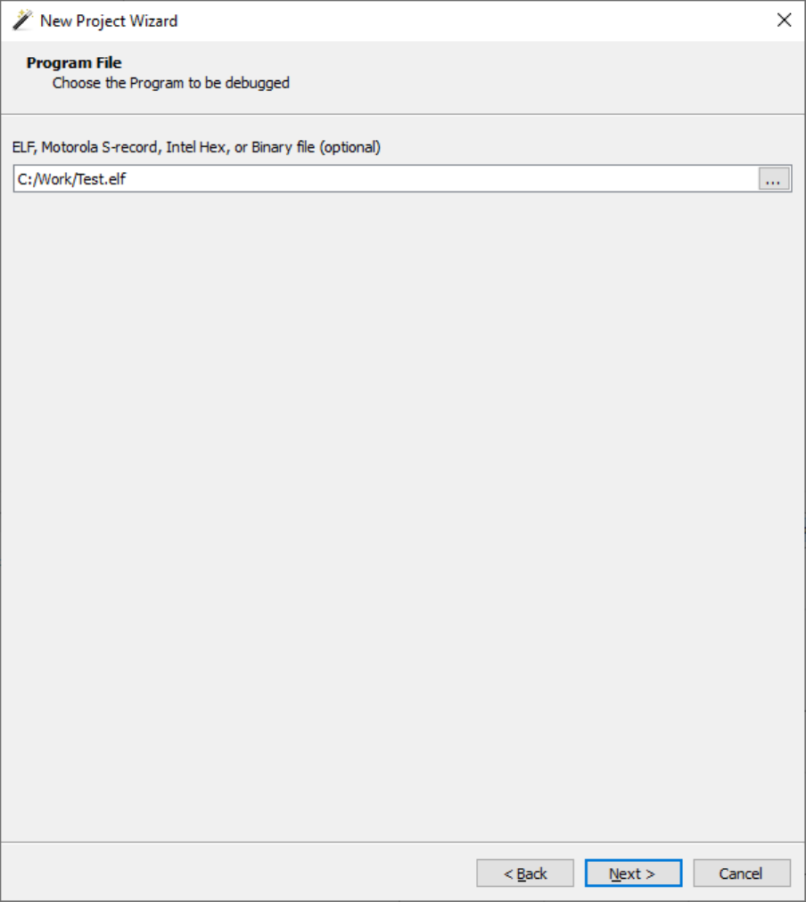
38 CHAPTER 2 Using Ozone for the first time
On the third page of the Project Wizard, the user specifies the debuggee.
Third page of the Project Wizard
Program File
This input field specifies the program to debug. Please note that only ELF or compatible pro-
gram files contain symbol information. When specifying a program file without symbol in-
formation, the debug features of Ozone are limited (see Symbol Information on page 181).
Ozone User Guide & Reference Manual (UM08025) © 2013-2024 SEGGER Microcontroller GmbH

39 CHAPTER 2 Using Ozone for the first time
On the last page of the Project Wizard, advanced project settings are defined.
Last page of the Project Wizard
Initial PC
Indicates how the debugger is to set the initial value of the PC register. The first option
is the default option. When the third option is checked, an Ozone expression denotes the
memory location of the initial PC value (see Working With Expressions on page 201). When
the fourth option is checked, an Ozone expression (constant) denotes the initial PC value.
Initial SP
Indicates how the debugger is to set the initial value of the SP register. The first option
is the default option. When the third option is checked, an Ozone expression denotes the
memory location of the initial SP value (see Working With Expressions on page 201). When
the fourth option is checked, an Ozone expression (constant) denotes the initial SP value.
Ozone User Guide & Reference Manual (UM08025) © 2013-2024 SEGGER Microcontroller GmbH
40 CHAPTER 2 Using Ozone for the first time
J-Link Script File
Sets the J-Link script which is to be executed upon target connection (see
Project.SetJLinkScript on page 343.
J-Link Log File
Sets the log file that is to receive logging output of the J-Link library (see Project.SetJLin-
kLogFile on page 344.
Completing the Project Wizard
When the user completes the Project Wizard, a new project with the specified settings is
created and the source file containing the program’s entry function is opened inside the
Source Viewer. The debugger is still offline, i.e. a connection to the target has not yet been
established. At this point, only windows whose content does not depend on target data
are operational and already display content. To put the remaining windows into use and to
begin debugging the program, the debug session must be started.
2.2.2 Starting the Debug Session
The debug session is started by clicking on the green start button in the debug toolbar or
by pressing the shortcut F5. After the startup procedure is complete, users may start to
debug the program using the controls of the Debug Menu. The debugging workflow when
using Ozone is described in detail in Chapter 5.
Ozone User Guide & Reference Manual (UM08025) © 2013-2024 SEGGER Microcontroller GmbH

Chapter 3
Graphical User Interface
This chapter provides a description of Ozone’s graphical user interface and its usage. The
focus lies on a brief description of graphical elements. Chapter 5 will revisit the debugger
from a functional perspective.
Ozone User Guide & Reference Manual (UM08025) © 2013-2024 SEGGER Microcontroller GmbH

42 CHAPTER 3 User Actions
3.1 User Actions
A user action (or action for short) is a particular operation within Ozone that can be triggered
via the user interface or programmatically from a script function. Ozone provides a set of
around 250 user actions.
3.1.1 Action Tables
Section Action Tables on page 42 provides multiple tables that contain quick facts on all
user actions. The action tables are particularly well suited as a reference when running the
debugger from the command prompt or when writing script functions.
3.1.2 Executing User Actions
User actions can (potentially) be executed in any of the ways listed below.
Execution Method Description
Menu A user action can be executed by clicking on its menu item.
Toolbar A user action can be executed by clicking on its tool button.
Hotkey A user action can be executed by pressing its hotkey.
Command Prompt
A user action can be executed by entering its command into
the Console Window’s command prompt.
Script Function
A user action can be executed by placing its command into a
script function.
However, some user actions do not have an associated text command and thus cannot
be executed from the command prompt or from a script function. On the other hand,
some actions can only be executed from these locations, but have no affiliated user inter-
face element. Furthermore, some actions do not provide a hotkey. Section User Actions
on page 42 provides information about which method of execution is available for the
different user actions.
3.1.2.1 User Action Hotkeys
A user action that belongs to a particular debug window may share the same hotkey with
another window-local user action. As a rule of thumb, a window-local user action can only
be triggered via its hotkey when the window containing the action is visible and has the
input focus. On the contrary, global user actions have unique hotkeys that can be triggered
without restriction.
3.1.3 Dialog Actions
Several user actions execute a dialog. The fact that a user action executes a dialog is
indicated by three dots that follow the action’s name within user interface menus.
Ozone User Guide & Reference Manual (UM08025) © 2013-2024 SEGGER Microcontroller GmbH

43 CHAPTER 3 Main Window
3.2 Main Window
Ozone’s Main Window consists of the following elements, listed by their location within the
window from top to bottom:
• Menu Bar
• Tool Bar
• Content Area
• Status Bar
These components will be explained further down this chapter. First, the Main Window is
described:
Main Window hosting debug information windows
In its center, the Main Window hosts the source code document viewer, or Source Viewer
for short. The Source Viewer is surrounded by three content areas to the left, right and
on the bottom. In these areas, users may arrange debug information windows as desired,
as described in section Window Layout on page 51. The only window that cannot be
undocked or repositioned is the Source Viewer itself.
Ozone User Guide & Reference Manual (UM08025) © 2013-2024 SEGGER Microcontroller GmbH

44 CHAPTER 3 Menu Bar
3.3 Menu Bar
Ozone’s Main Window provides a menu bar that categorizes all user actions into five func-
tional groups. It is possible to control the debugger from the menu bar alone. The five
menu groups are described below.
3.3.1 File Menu
The File Menu hosts actions that perform file sys-
tem and related operations (see File Actions on
page 284).
New
This submenu hosts actions to create a new
project and to run the Project Wizard (see
Project Wizard on page 34).
Open
Opens a project-, program-, data- or source-file
(see File.Open on page 293).
Open Folder...
A submenu with multiple entries to open a spe-
cific directory in the standard file explorer:
• Project Folder: opens the project file
directory
• Application Folder: opens the directory
containing the program file
• Source Folder: opens the directory containing the active source document
• Ozone Folder: opens the directory containing the Ozone executable
(see File.Open on page 293).
Edit Project File
Opens the project file within the Source Viewer.
Save Project as
Opens a dialog that lets users save the current project to the file system.
Save <file>
Saves all changes made to the active document, i.e. the document currently shown within
the Source Viewer.
Save <file> As...
Opens a dialog that lets users save the active document under a new path to the file system.
The active document will be closed and reopened from its new location.
Save Copy Of <file> As...
Opens a dialog that lets users save a copy of the active document to the file system.
Save All
Saves all modified Source Viewer documents and project files.
Ozone User Guide & Reference Manual (UM08025) © 2013-2024 SEGGER Microcontroller GmbH

45 CHAPTER 3 Menu Bar
Recent Projects
The “Recent Projects” submenu contains a list of recently used projects. When an entry is
selected, the associated project is opened.
Recent Programs
The “Recent Programs” submenu contains a list of recently opened program files. When an
entry is selected, the associated program file is opened.
Export
A submenu that hosts an entry for each of Ozone’s data exports:
Export Dialog Command
Code profile Code Profile Export Dialog Export.CodeProfile
Disassembly Disassembly Export Dialog Export.Disassembly
Instruction Instruction Trace Export Dialog Export.Trace
Power graphs Power Sampling Window Export.PowerGraphs
Data graphs Data Sampling Window Export.DataGraphs
3.3.2 View Menu
The View Menu contains an entry for each debug information window. By clicking on an
entry, the corresponding window is added to the Main Window at the last used position
(see Opening and Closing Windows on page 60).
embOS
If an RTOS awareness plugin has been loaded using action Project.SetOSPlugin, an addi-
tional entry for the RTOS Window (see RTOS Window on page 151) is added to the View
Menu.
SmartView
If a SmartView plugin has been loaded using action Project.SetSmartViewPlugin, an addi-
tional entry for the SmartView Window (see SmartView Window on page 143) is added
to the view menu.
Toolbars
This submenu hosts three checkable actions that define which toolbars are visible (see
Toolbars on page 49).
Enter/Exit Full Screen
Enters or exit full screen mode.
3.3.3 Find Menu
The Find Menu hosts actions that locate program symbols
and text patterns.
Find...
Opens the Quick Find Widget in text search mode.
Find In Files...
Opens the Find In Files Dialog
Ozone User Guide & Reference Manual (UM08025) © 2013-2024 SEGGER Microcontroller GmbH

46 CHAPTER 3 Menu Bar
Find In Trace...
Opens the Find In Trace Dialog
Find Function...
Opens the Quick Find Widget in function search mode.
Find Global Data...
Opens the Quick Find Widget in global data search mode.
Find Source Files...
Opens the Quick Find Widget in source file search mode.
3.3.4 Debug Menu
The Debug Menu hosts actions that control program ex-
ecution (Debug Actions on page 283).
Start/Stop Debugging
Starts the debug session, if it is not already started.
Stops the debug session otherwise.
Continue/Halt
Resumes program execution, if the program is halted.
Halts program execution otherwise.
Reset
Resets the program using the last employed reset mode. Other reset modes can be executed
from the action’s submenu (see Reset on page 187).
Step Over
Steps over the current source code line or machine instruction, depending on the active
code window (see Active Code Window on page 52 and Step on page 187). Context
aware stepping is supported, if enabled.
Step Into
Steps into the current subroutine or performs a single instruction step, depending on the
active code window (see Active Code Window on page 52 and Step on page 187).
Step Out
Steps out of the current subroutine (see Step on page 187).
Load/Save Snapshot
Opens the Snapshot Dialog (see Snapshot Dialog on page 78).
3.3.5 Tools Menu
The Tools Menu hosts dialog actions that allow users
to edit Ozone’s graphical and behavioral settings (see
Tools Actions on page 288).
J-Link Settings
Opens the J-Link-Settings Dialog that enables users
to specify J-Link/J-Trace specific settings such as the
Ozone User Guide & Reference Manual (UM08025) © 2013-2024 SEGGER Microcontroller GmbH

47 CHAPTER 3 Menu Bar
target device and debug interface to be used (see J-Link Settings Dialog on page 76).
Trace Settings
Opens the Trace Settings Dialog that is provided to configure trace (see Trace Settings
Dialog on page 83).
Semihosting Settings
Opens the Semihosting Settings Dialog that is provided to configure semihosting operations
(see Semihosting Settings Dialog on page 81).
Preferences
Opens the User Preference Dialog that enables users to specify behavioral and visual pref-
erences of the debugger (see User Preference Dialog on page 85).
System Variables
Opens the System Variable Editor that enables users to configure project-specific behavioral
settings of the debugger (see System Variable Editor on page 82).
3.3.6 Window Menu
The Window Menu lists all open windows and documents and provides actions to alter the
window and document state.
Close Window
Closes the debug window that contains the input focus.
Close All Windows
Closes all debug windows.
Undock
Undocks the debug window that contains the input focus.
Window List
The list of open debug information windows. By se-
lecting an item, the corresponding debug window is
opened and gains the input focus.
Close Document
Closes the active source document.
Close All Documents
Closes all source documents.
Close All Unedited Documents
Closes all unedited source documents.
Document List
The list of open source documents is appended to the window menu.
3.3.7 Help Menu
User help related actions.
User Guide
Opens the user guide and reference manual.
Ozone User Guide & Reference Manual (UM08025) © 2013-2024 SEGGER Microcontroller GmbH

49 CHAPTER 3 Toolbars
3.4 Toolbars
Three of Ozone’s main menu groups − File, Debug and View − have affiliated toolbars
that can be docked to the Main Window or positioned freely on the desktop. In addition, a
breakpoint toolbar is provided as well as a toolbar for accommodating custom buttons.
Category Toolbar
File
Debug
View
Break-
points
Custom
3.4.1 Showing and Hiding Toolbars
Toolbars can be added to the Main Window via the toolbar menu (View → Toolbars) or
by executing command Toolbar.Show using the toolbar’s name as parameter (e.g. Tool-
bar.Show("Debug")). Removing toolbars from the Main Window works the same way using
action Toolbar.Close (see Toolbar.Close on page 311).
3.4.2 Arranging Toolbars
Toolbars can be arranged either next to each other or above each other within the toolbar
area as desired. To reposition a toolbar, pick the toolbar handle and drag it to the desired
position.
3.4.3 Docking and Undocking Toolbars
Toolbars can be undocked from the toolbar area and positioned anywhere on the desktop.
To undock a toolbar, pick the toolbar’s handle and drag it outside the toolbar area. To hide
an undocked toolbar, follow the instructions of section Showing and Hiding Toolbars on
page 49.
3.4.4 Custom Toolbar
In contrast to the other toolbars the custom toolbar can be populated by the user. The user
may add buttons by means of the command Toolbar.AddCustomButton and when pressing
the button, a user function (see User Functions on page 221) in the Ozone project file will
be performed. In fact, pressing a button will have the same effect as invoking the function
via Script.Exec in the Command Prompt in the Console Window or directly inside the Ozone
project script (.jdebug).
The command specified to be executed when pressing the button is not checked upon
creation of the button. It is possible to specify a function call to a function that does not
exist or add unsuitable parameters. When pressing the button with an invalid command,
an error message will be displayed in the Console Window. If a legal command is passed,
the output that is to be expected when manually issuing the command will be displayed
in the Console Window.
The custom tool bar allows to disable buttons by means of the command Toolbar.Disable-
CustomButton and re-enable a button via Toolbar.EnableCustomButton. After creation a
button is always enabled. Clicking onto a disabled button does not have any effect.
A custom button may be removed by issuing the command Toolbar.RemoveCustomButton.
Ozone User Guide & Reference Manual (UM08025) © 2013-2024 SEGGER Microcontroller GmbH

50 CHAPTER 3 Status Bar
3.5 Status Bar
Ozone’s status bar displays information about the debugger’s current state. The status bar
is divided into three sections (from left to right):
• Status message and progress bar
• Window context information
• Connection state
Status bar
3.5.1 Status Message
On the left side of the status bar, a status message is displayed. The status message informs
about the following objects, depending on the situation:
Program State
By default, the status message informs about the program state, e.g. “Program running”.
Operation Status
When the debugger performs a lengthy operation, the status message displays the name
of the operation. In addition, a progress bar is displayed that indicates the progress of the
operation.
Context Help
When hovering the mouse cursor over a user interface element, the status message displays
a short description of the element.
3.5.2 Window Context Information
The middle section of the status bar displays information about the active debug information
window.
3.5.3 Connection State
The right section of the status bar informs about the debugger’s connection state. When
the debugger is connected to the target, the data transmission speed is displayed as well.
Ozone User Guide & Reference Manual (UM08025) © 2013-2024 SEGGER Microcontroller GmbH

51 CHAPTER 3 Debug Information Windows
3.6 Debug Information Windows
Ozone provides multiple debug information windows that cover different functional areas of
the debugger. This section describes the common features shared by all debug information
windows. An individual description of each debug information window is given in chapter
Debug Information Windows on page 51.
3.6.1 Context Menu
Each debug information window owns a context menu that
provides access to the window’s options. The context menu
can be opened by right-clicking on the window.
The state of switchable context menu options is main-
tained across sessions, i.e binary window options remain unchanged after Ozone was closed
and restarted.
3.6.2 Standard Shortcuts
Each debug information window supports the following set of standard hotkeys:
Hotkey Description
ESC Moves the input focus to the Source Viewer.
F6 Moves the input focus to next debug information window.
Shift+F6 Moves the input focus to previous debug information window.
Alt+x Closed the current debug information window.
3.6.3 Window Layout
Section Window Layout on page 51 describes how debug information windows are added
to, removed from and arranged on the Main Window.
3.6.4 Code Windows
Ozone includes two debug information windows that display the program’s source code and
assembly code, respectively. The code windows share several common properties that are
described in Code Windows on page 51.
3.6.5 Table Windows
Several of Ozone’s debug information windows are based on a joint table layout that pro-
vides a common set of features. A shared description of the table-based debug information
windows is given in Table Windows on page 51.
Ozone User Guide & Reference Manual (UM08025) © 2013-2024 SEGGER Microcontroller GmbH

52 CHAPTER 3 Code Windows
3.7 Code Windows
Ozone includes two debug information windows that display program code: the Source
Viewer and the Disassembly Window. These windows display the program’s source code and
assembly code, respectively. Both windows share multiple properties which are described
below. For an individual description of each window, refer to Source Viewer on page 155
and Disassembly Window on page 117.
3.7.1 Program Execution Point
Ozone’s code windows automatically scroll to the position of the PC line when the user steps
or halts the program. In case of the Source Viewer, the document containing the PC line
is automatically opened if required.
3.7.1.1 Active Code Window
At any point in time, either the Source Viewer or the Disassembly Window is the active
code window. The active code window determines the debugger’s stepping behavior, i.e.
whether the program is stepped per source code line or per machine instruction.
3.7.1.2 Recognizing the Active Code Window
The active code window can be distinguished from the inactive code window by a higher
color saturation level of the PC line (see the illustration below).
Source Viewer (inactive, left) and Disassembly Window (active, right)
3.7.1.3 Switching the Active Code Window
A switch to the active code window occurs either manually or automatically.
Manual Switch
A manual switch of the active code window can be performed by clicking on one of the
code windows. The selected window will become active while the other code window will
become inactive.
Automatic Switch to the Disassembly Window
When the user steps or halts the program and the PC is not affiliated with a source code
line via the program’s address mapping table, the debugger will automatically switch to the
Disassembly Window. The user can hereupon continue stepping the program on a machine
instruction level.
Automatic Switch to the Source Viewer
When the program was reset or halted and the PC is affiliated with a source code line, the
debugger will switch to the Source Viewer as its active code window.
3.7.2 Code Line Highlighting
Each code window applies distinct highlights to particular code lines. The table below ex-
plains the meaning of each highlight. Code line highlighting colors can be adjusted via the
Ozone User Guide & Reference Manual (UM08025) © 2013-2024 SEGGER Microcontroller GmbH

53 CHAPTER 3 Code Windows
User Preference Dialog (see User Preference Dialog on page 85) or via the command
Edit.Color (see Edit.Color on page 301).
Highlight Meaning
for (int i = 0) { The code line contains the program execution point (PC).
Function(x,y); The code line contains the call site of a function on the call stack.
for (int i = 0) { The code line is the selected line.
for (int i = 0) {
The code line contains the instruction that is currently selected
within the instruction trace window (see Backtrace Highlighting on
page 129).
3.7.3 Breakpoints
Ozone’s code windows provide multiple options to set, clear, enable, disable and edit break-
points. The different options are described below.
3.7.3.1 Toggling Breakpoints
Both code windows provide the following options to set or clear breakpoints on the selected
code line:
Method Set Clear
Context Menu Menu Item “Set Breakpoint” Menu Item “Clear Breakpoint”
Hotkey F9 F9
Breakpoint Bar Single-Click Single-Click
Breakpoints on arbitrary addresses and code lines can be toggled using the actions
Break.Set, Break.SetOnSrc, Break.Clear and Break.ClearOnSrc (see Breakpoint Actions on
page 282).
3.7.3.2 Enabling and Disabling Breakpoints
The breakpoint on the selected code line can be enabled or disabled by pressing the hotkey
Shift-F9. Breakpoints on arbitrary addresses and code lines can be enabled and disabled us-
ing actions Break.Enable, Break.Disable, Break.EnableOnSrc and Break.DisableOnSrc (see
Breakpoint Actions on page 282).
3.7.3.3 Editing Advanced Breakpoint Properties
Advanced breakpoint properties, such as the trigger condition or implementation type,
can be edited via the Breakpoint Properties Dialog (see Breakpoint Properties Dialog on
page 62) or via commands Break.Edit (see Break.Edit on page 361) and Break.SetType
(see Break.SetType on page 359).
3.7.3.4 Breakpoint Bar
Each code window hosts a breakpoint bar on its left side. The breakpoint bar displays
distinct icons that provide additional information about code lines. The following table gives
an overview.
Icon Meaning
The code line does not contain executable code.
The code line contains executable code.
A breakpoint is set on the code line.
The code line contains the PC instruction and will be executed next.
Ozone User Guide & Reference Manual (UM08025) © 2013-2024 SEGGER Microcontroller GmbH

54 CHAPTER 3 Code Windows
Icon Meaning
The code line contains a call site of a function on the call stack.
The code line contains the PC instruction and a breakpoint is set on the line.
The code line contains a call site and a breakpoint is set on the line.
The code line contains a tracepoint that starts trace.
The code line contains a tracepoint that stops trace.
The display of the breakpoint bar can be toggled from the User Preference Dialog (see User
Preference Dialog on page 85) or via command Edit.Preference (see Edit.Preference on
page 300).
3.7.4 Code Profile Information
The code windows are able to display code profile information within a switchable sidebar
area on the left side of the window.
3.7.4.1 Hardware Requirements
The code profile features of Ozone require the employed hardware setup to support in-
struction tracing (see Instruction Trace Window on page 128). To use Ozone’s full set of
trace features, a J-Trace PRO debug probe (see Streaming Trace on page 194) must be
employed.
3.7.4.2 Code Execution Counters
When code profiling features are supported by the
hardware setup, the code windows display a counter
next to each text line that contains executable code.
The counter indicates how often the source code line
or instruction was executed.
Resetting Execution Counters
The execution counters are reset automatically at the
same time the program is reset. A manual reset can
be performed via context menu or command Profile.Reset.
Toggling Execution Counters
The display of execution counters can be toggled via the context menu.
3.7.4.3 Execution Profile Tooltips
When hovering the mouse cursor over an execu-
tion counter, the execution profile of the affiliat-
ed source line or instruction is displayed within
a tooltip:
Fetched: number of times the instruction was
fetched from memory.
Executed: number of times the instruction was
executed.
Not-Executed: number of times the (conditional) instruction was fetched from memory
but not executed.
Load: number of times the instruction was fetched divided by the total amount of instruc-
tions fetched during program execution.
Ozone User Guide & Reference Manual (UM08025) © 2013-2024 SEGGER Microcontroller GmbH

55 CHAPTER 3 Code Windows
The execution profile of a source line is identical to the execution profile of the first instruc-
tion of the source line.
When user preference PREF_EXEC_PROFILE_RESPECTS_FILTERS is set, an instruction fil-
tered from the code coverage statistic will not be accounted for when computing the exe-
cution profiles of source lines and instructions. (see Adding and Removing Coverage Filters
on page 107).
3.7.4.4 Execution Profile Color-Codes
The background of an execution counter is painted in a style which conveys the execution
profile of the affiliated source line or instruction. The following styles are used:
Conditional instructions:
Style Description
instruction was never fetched for execution.
instruction has taken both execution paths.
instruction was always executed.
instruction was never executed.
Non-conditional instructions:
Style Description
instruction was never fetched for execution.
instruction was executed.
Source lines:
Style Description
no instruction of the source line was fetched for execution.
some instructions of the source line were fetched for execution, but not all.
all instructions of the source line were fetched for execution and at least one
conditional instruction of the source lines was always executed.
all instructions of the source line were fetched for execution and at least one
conditional instruction of the source lines was never executed.
all instructions of the source line were executed at least once and all condi-
tional instructions have taken both execution paths.
Changing Code Profile Colors
The colors used in the styles above can be adjusted via the User Preference Dialog (see User
Preference Dialog on page 85) or via command Edit.Color (see Edit.Color on page 301).
3.7.5 Text Cursor Navigation Shortcuts
Ozone’s code windows provide standard text navigation/selection hotkeys. The Shift key
can be held together with any of the below keys to extend the text selection to the new
cursor position.
Arrow key Moves the text cursor in the specified direction.
PgUp Moves the text cursor one page up.
PgDn Moves the text cursor one page down.
Ozone User Guide & Reference Manual (UM08025) © 2013-2024 SEGGER Microcontroller GmbH

56 CHAPTER 3 Code Windows
Arrow key Moves the text cursor in the specified direction.
Home Moves the text cursor to the start of the line.
End Moves the text cursor to the end of the line.
Ctrl+Left Moves the text cursor to the previous word.
Ctrl+Right Moves the text cursor to the next word.
Ctrl+Home Moves the text cursor to the start of the document.
Ctrl+End Moves the text cursor to the end of the document.
Ctrl+PgUp Moves the text cursor to the first visible line.
Ctrl+PgDn Moves the text cursor to the last visible line.
Ozone User Guide & Reference Manual (UM08025) © 2013-2024 SEGGER Microcontroller GmbH

57 CHAPTER 3 Table Windows
3.8 Table Windows
Several of Ozone’s debug information windows are based on a joint table layout that pro-
vides a common set of features. The Global Data Window illustrated below is an example
of a table-based debug information window.
3.8.1 Member Rows
A table row that displays a button on its
left side can be expanded to reveal its
contained entries. A table window where
multiple rows have been expanded at-
tains a tree structure as illustrated on the
right.
Member Display Limit
The number of child entries that can be
displayed for a table row can be limited via the User Preference Dialog. When table rows
are not shown due to the display limit, an indication is displayed as shown on the right.
3.8.2 Column Header
Hiding Columns
Each table column has an entry in the context menu of the ta-
ble header. When an entry is checked or unchecked, the cor-
responding table column is shown or hidden. The table head-
er context menu can be opened by right-clicking on the table
header.
Sorting Columns
Table rows can be sorted according to the values displayed in a
particular column. To sort a table according to a particular column, a left click on the column
header suffices. A sort indicator in the form of a small arrow indicates the column according
to which the table is currently sorted. The sort strategy depends on the data type of the
column.
3.8.3 Display Format
Ozone User Guide & Reference Manual (UM08025) © 2013-2024 SEGGER Microcontroller GmbH

58 CHAPTER 3 Table Windows
The table windows enable users to change the value display format of a particular (or all)
value items. If supported, the value display format can be changed via the window’s context
menu or via commands Window.SetDisplayFormat and Edit.DisplayFormat (see Window
Actions on page 289).
3.8.4 Filter and Total Value Bars
Each table window provides two distinct header rows that are always visible, regardless of
the scroll bar positions.
The filter bar (1) enables users to filter the table content. When a filter is set on a table
column, only table rows whose column value matches the filter stay visible.
The total value bar (2) informs about the aggregate value of a table column. The aggregate
value is the sum of all values currently shown within the column.
The display state of the filter and total value bars (shown or hidden) can be toggled via
the context menu of the table window.
3.8.4.1 Value Range Filters
Columns that display numerical data accept value range filter input. A value range filter is
specified in any of the following formats:
Format Description
x-y keep items whose column value is contained within the range [x,y].
>x keep items whose column value is greater than x.
≥x keep items whose column value is greater than or equal to x.
<x keep items whose column value is less than x.
≤x keep items whose column value is less than or equal to x.
3.8.4.2 Filter Bar Context Menu
In addition to the standard text interaction options, the filter bar context menu provides
the following actions:
Clear All Filters
Clears all column filters.
Set Filter...
Opens the filter input dialog.
3.8.5 CSV Export
All table windows provide a context menu entry
that enables users to export the (filtered) table
content to a comma-separated values file.
3.8.6 Change Level Highlighting
Ozone User Guide & Reference Manual (UM08025) © 2013-2024 SEGGER Microcontroller GmbH
59 CHAPTER 3 Table Windows
Multiple debug information windows highlight numeric values according to recency of their
last change (see Change Level Highlighting on page 58).
3.8.7 Letter Key Navigation
By repeatedly pressing a letter key within a table window, the table rows that start with
the given letter are scrolled into view one after the other.
3.8.8 Table Window Preferences
Section Table Window Settings on page 88 lists all user preference settings pertaining
to table windows.
Ozone User Guide & Reference Manual (UM08025) © 2013-2024 SEGGER Microcontroller GmbH

60 CHAPTER 3 Window Layout
3.9 Window Layout
This section describes how debug information windows can be added to, removed from and
arranged on the Main Window.
3.9.1 Opening and Closing Windows
Opening Windows
Windows are opened by clicking on the affiliated view menu item (e.g. View → Breakpoints)
or by executing the command Window.Show using the window’s name as parameter (e.g.
Window.Show("Breakpoints")). When a window is opened, it is added to its last known
position on the user interface.
Closing Windows Programmatically
Windows can be closed via command Window.Close using the window’s name as parameter.
3.9.2 Undocking Windows
Windows can be undocked from the Main Window by dragging or double-clicking the win-
dow’s title bar. An undocked window can be freely positioned and resized on the desktop.
Undocked disassembly window floating over the Main Window
3.9.3 Docking and Stacking Windows
Windows can be docked on the left, right or bottom side of the Main Window by dragging
and dropping the window at the desired position. If a window is dragged and dropped over
another window the windows are stacked. More than two windows can be stacked above
each other.
Stacked debug information windows
Ozone User Guide & Reference Manual (UM08025) © 2013-2024 SEGGER Microcontroller GmbH

61 CHAPTER 3 Change Level Highlighting
3.10 Change Level Highlighting
Ozone emphasizes changed values with a set of three different colors that indicate the
recency of the change. The change level of a particular value is defined as the number of
times the program was stepped since the value has changed. The table below depicts the
default colors that are assigned to the different change levels.
Change Level Meaning
Level 1 The value has changed one program step ago.
Level 2 The value has changed two program steps ago.
Level 3 The value has changed three program steps ago.
Level 4 (and above)
The value has changed 4 or more program steps ago or does
not display change levels.
Both foreground and background colors used for change level highlighting can be adjusted
via the User Preference Dialog (see User Preference Dialog on page 85 or via command
Edit.Color (see Edit.Color on page 301).
Ozone User Guide & Reference Manual (UM08025) © 2013-2024 SEGGER Microcontroller GmbH

62 CHAPTER 3 Dialogs
3.11 Dialogs
This section describes the different dialogs that are employed within Ozone.
3.11.1 Breakpoint Properties Dialog
The Breakpoint Properties Dialog enables users to edit advanced breakpoint properties
such as the trigger condition and the implementation type. The dialog can be accessed via
the context menu of the Source Viewer, Disassembly Window or Breakpoints/Tracepoints
Window. Breakpoint properties can also be set programmatically using actions Break.Edit
(see Break.Edit on page 361) and Break.SetType (see Break.SetType on page 359).
State
Enables or disables the breakpoint.
Permitted Implementation
Sets the breakpoint’s permitted implementa-
tion type (see Break.SetType on page 359).
Skip Count
Program execution can only halt each Skip-
Count+1 number of times the breakpoint is hit.
Furthermore, the remaining trigger conditions
must be met in order for program execution to
halt at the breakpoint.
Reload
When unchecked, the skip count condition is
deactivated as soon as the program halts at the
breakpoint for the first time.
Task
Specifies the RTOS task that must be running
in order for the breakpoint to be triggered. The
RTOS task that triggers the breakpoint can be
specified either via its name or via its ID. When
the field is left empty, the breakpoint is task-
insensitive.
Condition
An integer-type or boolean-type symbol ex-
pression that must be met in order for program execution to halt at the breakpoint. When
option “trigger when true” is selected, the expression must evaluate to a non-zero value in
order for the breakpoint to be triggered. When option “trigger when changed” is selected,
the breakpoint is triggered each time the expression value changed since the last time the
breakpoint was encountered.
Extra Actions
Specifies the additional actions that are performed when the breakpoint is hit. The provid-
ed options are a text message that is printed to the Console Window, a message that is
displayed within a popup dialog and a script function that is executed (see Project Script
on page 220).
Note
Ozone User Guide & Reference Manual (UM08025) © 2013-2024 SEGGER Microcontroller GmbH

63 CHAPTER 3 Dialogs
Due to hardware limitations, executing a script function is not supported for data break
points.
Ozone User Guide & Reference Manual (UM08025) © 2013-2024 SEGGER Microcontroller GmbH

64 CHAPTER 3 Dialogs
3.11.2 Code Profile Export Dialog
The Code Profile Export Dialog is provided to save the application’s code profile to a text
or a CSV file (see Code Profile Window on page 105).
Code Profile Export Dialog
Report Scope
Functions to be covered by the output file.
Tree View
Allows users to select the functions to be covered by the output file.
Output Format
Output file format. The default option “Report” generates a human-readable text file. The
alternate option “CSV” generates a comma-separated values file that can be used with
table-processing software such as excel.
CSV Format
Available when output file format is “CSV”. Specifies which program entities within the se-
lected report scope are to be exported. For example, if the report scope contains a single
file and the selected CSV format is “Instructions”, then a code profile report about all in-
structions within the selected file is generated.
Ozone User Guide & Reference Manual (UM08025) © 2013-2024 SEGGER Microcontroller GmbH

65 CHAPTER 3 Dialogs
Export File Paths
Specifies if absolute file paths (checked) or file names (unchecked) are to be exported.
Output File
Output file path.
3.11.2.1 Commands
The functionality of the code profile export dialog can be accessed from script functions
using command Export.CodeProfile on page 303.
3.11.2.2 Code Profile Report
Shown below is the content of a text file generated by the Code Profile Export Dialog.
Code Profile Report Example
Ozone User Guide & Reference Manual (UM08025) © 2013-2024 SEGGER Microcontroller GmbH

66 CHAPTER 3 Dialogs
3.11.3 Data Breakpoint Dialog
The Data Breakpoint Dialog enables users to place data breakpoints on global program
variables and individual memory addresses. Please refer to Data Breakpoints on page 191
for further information on data breakpoints in Ozone.
The dialog can be accessed from the con-
text menu of the Breakpoints/Tracepoints win-
dow (see Breakpoints/Tracepoints Window on
page 95) or from the context menu of the
data symbol windows.
Data Location
The data location pane enables users to speci-
fy the memory address(es) to be monitored for
IO accesses. When field “From Expression” is
checked, the memory address results from the
evaluation of a symbol expression (see Work-
ing With Expressions on page 201. Otherwise,
the memory address is specified manually. The
Mask field specifies the bits of the input address
which are ignored when evaluating the location
condition. An address mask of 0 monitors ex-
actly and only the input address for IO access-
es. An address mask of 0xFFFFFFFF monitors
all memory addresses.
Access Condition
The access condition pane enables users to
specify the type and size of a memory access
that triggers the data breakpoint.
Value Condition
The value condition pane enables users to specify the memory data value required to trigger
the data breakpoint. The mask field specifies the bits of the memory data value which are
to be ignored when evaluating the condition. A value mask of 0 performs an exact match
against the value entered within the “Value” field. A value mask of 0xFFFFFFFF matches any
value and has the same effect as selecting “Ignored”. The value condition can be disabled
by checking the “Ignored” field.
3.11.3.1 Applying Changes
By pressing the OK button, a data breakpoint with the specified attributes is set in target
hardware and added to the Breakpoints/Tracepoints Window. In case the debugger is dis-
connected from the target, the data breakpoint is added to the Breakpoints/Tracepoints
Window and scheduled to be set in target hardware when the debug session is started.
Note
Due to hardware limitations, executing a script function, as is available for source- or
instruction breakpoints, is not supported for data break points.
Ozone User Guide & Reference Manual (UM08025) © 2013-2024 SEGGER Microcontroller GmbH

67 CHAPTER 3 Dialogs
3.11.4 Disassembly Export Dialog
The Disassembly Export Dialog is provided to save the disassembly of arbitrary memory
address ranges, including source code and symbol information, to CSV and assembly code
files.
Disassembly Export Dialog
CSV
Disassembly data is exported in CSV format.
Assembly Code
Disassembly data is exported to a single recompilable GNU-syntax assembly code file. This
option is currently only available when debugging on Cortex-M.
Entity / Function
Selects the address range to be exported.
Remove Trailing NOPs at the end of functions
Indicates if “no-operation” instructions, emitted by the compiler for function alignment
purposes, are to be filtered from the output.
3.11.4.1 Exemplary Output
Shown below is an excerpt of a CSV file that was generated using the Disassembly Export
Dialog.
Ozone User Guide & Reference Manual (UM08025) © 2013-2024 SEGGER Microcontroller GmbH


69 CHAPTER 3 Dialogs
3.11.5 Find In Files Dialog
The Find In Files Dialog enables users to search for text patterns within multiple source
code documents.
Find What
Defines the search pattern. The search
pattern is either a plain text, an expres-
sion containing wild cards (see Use Unix
Style Wildcards) or a regular expres-
sion (see Use Regular Expressions), de-
pending on the type of the search be-
low.
Look In
Selects the source code documents that
are to be included in the search (see File
Search Scope on page 70).
Search Inline Assembly Code
Also search within source-inline assem-
bly code lines.
Match Case
Specifies if the letter casing of the
search pattern is relevant.
Match Whole Word
Specifies if a match must start and end
at word boundaries.
This setting is mutual exclusive with us-
ing wild cards and regular expressions.
Use Unix Style Wildcards
Indicates if the search pattern is to be interpreted as an expression containing wildcards.
This setting is mutual exclusive with matching whole words and using regular expressions.
Use Regular Expressions
Indicates if the search pattern is to be interpreted as a regular expression. In that case,
the search is conducted on the basis of a regular expression pattern match.
This setting is mutual exclusive with matching whole words and using wild cards.
Show File Paths
Indicates if the file path of matches should be included in the search result. The search
result is displayed within the Find Results Window (see Find Results Window on page 121).
Find All
Finds all occurrences of the search pattern in the selected search scope. The search result
is printed to the Find Results Window.
Find Next/Previous
Finds the next/previous occurrence of the search pattern in the selected search scope.
When a match is found, it is highlighted within the Source Viewer. After closing the Find
Ozone User Guide & Reference Manual (UM08025) © 2013-2024 SEGGER Microcontroller GmbH
70 CHAPTER 3 Dialogs
In Files Dialog, the next/previous occurrence of the search pattern can be located using
shortcut F3/Shift+F3.
In Addtion, shortcut Ctrl+F3 is provided to locate the next occurrence of the word under
the cursor without the need to open the Find In Files Dialog.
3.11.5.1 File Search Scope
Find in files can be conducted in one of three search scopes. The desired search scope can
be specified via the “Look In” selection box of the Find In Files Dialog.
Search Scope Description
Current Document The search is conducted within the active document.
All Open Documents
The search is conducted within all documents that are open
within the Source Viewer.
Current Project
The search is conducted within all source files used to com-
pile the debuggee.
Ozone User Guide & Reference Manual (UM08025) © 2013-2024 SEGGER Microcontroller GmbH

71 CHAPTER 3 Dialogs
3.11.6 Find In Trace Dialog
The Find In Trace Dialog enables users to search for text patterns within the content of the
Instruction Trace Window (see Instruction Trace Window on page 128).
Find what
Defines the search pattern. The search
pattern is either a plain text, an expres-
sion containing wild cards (see Use Unix
Style Wildcards) or a regular expres-
sion (see Use Regular Expressions), de-
pending on the type of the search be-
low.
Look where
Defines the text columns to include
within the search. When a match spans
multiple text columns, the checkboxes
of these text columns must be checked
in order for the match to be accounted.
Address
Defines if the address text column is in-
cluded within the search.
Encoding
Defines if the instruction encoding text
column is included within the search.
Assembly Code
Defines if the assembly code text col-
umn (including mnemonics, operands
and assembly comments) is included
within the search.
Source Code
Defines if the source code text column is included within the search.
Function Header
Defines if call frame header titles are included within the text search (see Call Frames).
Match Case
Specifies if the letter casing of the search pattern is relevant.
Match Whole Word
Specifies if a match must start and end at word boundaries.
This setting is mutual exclusive with using wild cards and regular expressions.
Use Unix Style Wildcards
Indicates if the search pattern is to be interpreted as an expression containing wildcards.
This setting is mutual exclusive with matching whole words and using regular expressions.
Ozone User Guide & Reference Manual (UM08025) © 2013-2024 SEGGER Microcontroller GmbH
72 CHAPTER 3 Dialogs
Use Regular Expressions
Indicates if the search pattern is to be interpreted as a regular expression. In that case,
the search is conducted on the basis of a regular expression pattern match.
This setting is mutual exclusive with matching whole words and using wild cards.
Find All
Finds all occurrences of the search pattern within the selected text columns. The search
result is printed to the Find Results Window.
Find Next/Previous
Finds the next/previous occurrence of the search pattern within the selected text columns.
When a match is found, it is highlighted within the Instruction Trace Window. After closing
the Find In Trace Dialog, the next/previous occurrence of the search pattern can be located
using shortcut F3/Shift+F3.
In Addtion, shortcut Ctrl+F3 is provided to locate the next occurrence of the word under
the cursor without the need to open the Find In Trace Dialog.
Ozone User Guide & Reference Manual (UM08025) © 2013-2024 SEGGER Microcontroller GmbH

73 CHAPTER 3 Dialogs
3.11.7 Memory Dialog
The Memory Dialog is a multi-functional dialog that is used to:
• Dump target memory data to a binary file
• Download data from a binary file to target memory
• Fill a target memory area with a specific value
All values entered into the Memory Dialog are interpreted as hexadecimal numbers, even
when not prefixed with “0x”.
3.11.7.1 Save Memory Data
In its first application, the Memory Di-
alog is used to save target memory
data to a binary file.
File
The destination binary file (*.bin) into
which memory data should be stored.
By clicking on the dotted button, a file
dialog is displayed that lets users se-
lect the destination file.
Address
The addresses of the first byte stored
to the destination file. Size The number of bytes stored to the destination file.
3.11.7.2 Load Memory Data
In its second application, the Memory Dialog is used to write data from a binary file to
target memory.
File
The binary file (*.bin) whose contents are to be written to target memory. By clicking on
the dotted button, a file dialog is displayed that lets users choose the data file.
Address
The download address, i.e. the memory address that should store the first byte of the data
content.
End Address / Size
The number of bytes that should be written to target memory starting at the download
address.
3.11.7.3 Fill Memory
In its third application, the Memory Di-
alog is used to fill a memory area with
a specific value.
Fill Value
The fill value.
Width
The word width (i.e. the number of
bytes) the fill value consumes. Sup-
Ozone User Guide & Reference Manual (UM08025) © 2013-2024 SEGGER Microcontroller GmbH
74 CHAPTER 3 Dialogs
ported values are 1, 2, 3, 4 and 8 bytes. This allows for memory being filled byte- word-
or double-word wise, and also supports filling frame buffers encoding a color in 3 bytes.
Address
The start and end addresses (inclusive) of the memory area.
End Address / Size
The size of the memory area.
Ozone User Guide & Reference Manual (UM08025) © 2013-2024 SEGGER Microcontroller GmbH

75 CHAPTER 3 Dialogs
3.11.8 Instruction Trace Export Dialog
The Instruction Trace Export Dialog is provided to save the current instruction trace record
to a CSV file.
Instruction Trace Export Dialog
Maximum Instruction Count
Maximum number of instructions to export.
Output File
Output file.
3.11.8.1 Exemplary Output
Shown below is an excerpt of a CSV file that was generated using the Instruction Trace
Export Dialog.
CSV content generated by the Instruction Trace Export Dialog
Ozone User Guide & Reference Manual (UM08025) © 2013-2024 SEGGER Microcontroller GmbH

76 CHAPTER 3 Dialogs
3.11.9 J-Link Settings Dialog
The J-Link-Settings-Dialog enables users to configure J-Link/J-Trace related settings, such
as the target model and the debug interface. Refer to Project Wizard on page 34 for a
description of these settings.
J-Link Settings Dialog
3.11.9.1 Opening the J-Link Settings Dialog
The J-Link Settings Dialog can be opened from the Tools Menu or by executing command
Tools.JLinkSettings.
3.11.9.2 Applying Changes
Save To Project
By clicking the “Save To Project” button, the selected J-Link settings are written to the
project file and thereby applied persistently.
OK
By clicking the Ok button, the selected J-Link settings are applied to the current session
only.
Ozone User Guide & Reference Manual (UM08025) © 2013-2024 SEGGER Microcontroller GmbH

77 CHAPTER 3 Dialogs
3.11.10 Project Load Diagnostics Dialog
The Project Load Diagnostics Dialog notifies users about erroneous project settings and
other project loading issues, such as syntax errors. This dialog is only shown when required,
and only during loading of a project file.
Project Load Diagnostics Dialog
3.11.10.1 Project Load Diagnostics
For each issue encountered during project loading, an entry is added to the load diagnostics
table. This entry provides a basic description of the issue and an index into Ozone’s appli-
cation message table. The application message table usually provides further information
about the issue (see Errors and Warnings on page 275).
3.11.10.2 Suggested Fix-Ups
For each issue that the debugger knows how to resolve automatically, an entry is added
to the fix-ups table.
3.11.10.3 Buttons
Apply selected fix-ups
Applies the selected fix-ups and updates the project file.
Edit Project File
Closes the dialog, cancels project loading and opens the project file within the Source
Viewer.
Reload Project
Closes the dialog and reloads the project file.
Continue
Closes the dialog and continues project file loading.
Cancel
Closes the dialog and unloads the project.
Ozone User Guide & Reference Manual (UM08025) © 2013-2024 SEGGER Microcontroller GmbH

78 CHAPTER 3 Dialogs
3.11.11 Snapshot Dialog
The snapshot dialog enables users to save and load debug snapshots (see Debug Snapshots
on page 211). The dialog has two display modes: a “save snapshot” and a “load snapshot”
mode.
3.11.11.1 Load Snapshot
When opened in load mode, the snapshot dialog informs about basic properties of the
snapshot to be loaded, such as the employed target device and program file. The snapshot
dialog can be opened in load mode from the Debug Menu or by executing command De-
bug.LoadSnapshot.
Snapshot Load Diagnostics
A requirement for the successful restoration of a debug session from a snapshot is that
the snapshot settings match the project settings. In particular, the program file must bi-
nary-match the program file at the time the snapshot was saved. When any mismatches
occur, the snapshot load diagnostics dialog will be shown to inform the user.
3.11.11.2 Save Snapshot
When opened in save mode, the snapshot dialog enables users to define what data will be
saved to the snapshot. In particular, the dialog provides two sub-dialogs that allow to define
Ozone User Guide & Reference Manual (UM08025) © 2013-2024 SEGGER Microcontroller GmbH

79 CHAPTER 3 Dialogs
what components of the system state, i.e. which target memory regions and registers, are
to be saved.
The snapshot dialog can be opened in save mode from the Debug Menu or by executing
command Debug.SaveSnapshot.
3.11.11.3 Memory Selection
The “Memory Selection” sub-dialog of the snapshot dialog enables users to define the target
memory regions to be stored to the snapshot.
Import
Adds the memory regions defined by an Embedded Studio memory map file to the list.
Restore Defaults
Resets to the default configuration, which is:
• all FLASH and RAM region defined for the target by J-Link/J-Trace.
• all ELF program data sections with the allocatable flag (A) set.
Ozone User Guide & Reference Manual (UM08025) © 2013-2024 SEGGER Microcontroller GmbH

80 CHAPTER 3 Dialogs
Save to Project
Applies changes persistently by writing them to the user file of the project.
Ok
Applies changes to the current session only.
3.11.11.4 Register Selection
The “Register Selection” sub-dialog of the snapshot dialog enables users to define the target
registers to be stored to the snapshot.
Users may save CPU registers and peripheral registers to the snapshot, although only CPU
registers will be automatically restored when the snapshot is loaded (see Advanced System
Restore on page 211).
Save to Project
Applies changes persistently by writing them to the user file of the project.
Ok
Applies changes to the current session only.
Ozone User Guide & Reference Manual (UM08025) © 2013-2024 SEGGER Microcontroller GmbH

81 CHAPTER 3 Dialogs
3.11.12 Semihosting Settings Dialog
The semihosting settings dialog enables users to conveniently edit any of the semihosting
settings described in section Project.ConfigSemihosting on page 337. The dialog can be
opened from the tools menu or the context menu of the Terminal Window (see Terminal
Window on page 161). An elaborate description of Ozone’s semihosting facility can be
found in section Semihosting on page 197.
Save to Project
Applies changes persistently by writing them to the user file of the project.
OK
Applies changes to the current session only.
Ozone User Guide & Reference Manual (UM08025) © 2013-2024 SEGGER Microcontroller GmbH

82 CHAPTER 3 Dialogs
3.11.13 System Variable Editor
Ozone defines a set of system variables that control project-specific behavioral aspects
of the debugger. The System Variable Editor lets users observe and edit these variables
in a tabular fashion. A description of each system variable is provided by section System
Variable Identifiers on page 269.
System Variable Editor
3.11.13.1 Opening the System Variable Editor
The System Variable Editor can be opened from the Main Menu (Edit → System Variables)
or by executing command Tools.SysVars.
3.11.13.2 Editing System Variables Programmatically
The command Edit.SysVar on page 301 is provided to manipulate system variables within
script functions or at the command prompt (see Command Prompt on page 110).
3.11.13.3 Applying Changes
Save To Project
By clicking the “Save To Project” button, the displayed system variable state is written to
the project file and thereby applied persistently.
Ok
By clicking the Ok button, the selected J-Link settings are applied to the current session
only.
Ozone User Guide & Reference Manual (UM08025) © 2013-2024 SEGGER Microcontroller GmbH

83 CHAPTER 3 Dialogs
3.11.14 Trace Settings Dialog
The Trace Settings Dialog enables the user to configure the available trace input sources.
Trace Source
Selects the trace source to be used:
Trace Source Description
Trace Pins
Instruction Trace (ETM) data is read realtime-continuously from the
target’s trace pins and supplied to Ozone’s Trace Windows. This option
requires a J-Trace debug probe to be employed (see Streaming Trace
on page 194).
Trace Buffer
Instruction Trace (ETM) data is read from the target’s trace data
buffer and supplied to Ozone’s Trace Windows.
SWO
“Printf-type” textual application (ITM) data is read via the SWO chan-
nel and supplied to Ozone’s Terminal Window on page 161.
For detailed information on ETM and ITM trace and how to set up your hardware and soft-
ware accordingly, please consult the J-Link User Guide .
Note
The simultaneous use of multiple trace sources in Ozone is currently not supported.
Timestamps (Trace Pins, SWO)
Specifies if the target is to output cycle counters (instruction execution timestamps) mul-
tiplexed with the pin trace. The cycle counters are employed by various debug windows to
present users with information about the CPU time spend inside individual program entities.
CPU Frequency (Trace Pins)
Specifies the constant conversion factor to use when converting cycle counters to time
values and vice versa.
Ozone User Guide & Reference Manual (UM08025) © 2013-2024 SEGGER Microcontroller GmbH
84 CHAPTER 3 Dialogs
Trace Port Width (Trace Pins)
Specifies the number of trace pins comprising the target’s trace port (see Project.SetTra-
cePortWidth on page 340).
Maximum Instruction Count (Trace Pins)
The maximum number of instructions that are read from the selected trace source before
readout is stopped.
Trace Timing (Trace Pins)
Specifies the software delays to be applied to the individual trace port data lines. This essen-
tially performs a software phase correction of the trace port’s data signals (see Project.Set-
TraceTiming on page 340).
CPU frequency (SWO)
Specifies the core frequency of the target in Hz. (see Project.ConfigSWO on page 341).
SWO Frequency (SWO)
Specifies the signal frequency of the SWO trace interface in Hz. (see Project.ConfigSWO
on page 341).
Data from stimulus ports (SWO)
Specifies the stimulus ports that are used for transferring SWO data. (see Edit.SysVar using
argument VAR_SWO_PORTMASK).
3.11.14.1 Opening the Trace Settings Dialog
The Trace Settings Dialog can be opened from the Main Menu (Edit → Trace Settings) or
by executing command Tools.TraceSettings.
3.11.14.2 Applying Changes
Save To Project
By clicking the “Save To Project” button, the selected trace settings are written as Ozone
commands to the project file and thereby applied persistently.
Ok
By clicking the Ok button, the selected trace settings are applied to the current session only.
Ozone User Guide & Reference Manual (UM08025) © 2013-2024 SEGGER Microcontroller GmbH

85 CHAPTER 3 Dialogs
3.11.15 User Preference Dialog
The User Preference Dialog provides multiple user-specific options. In particular, fonts,
colors and switchable items such as line numbers and sidebars can be customized.
User preference dialog
3.11.15.1 Opening the User Preference Dialog
The User Preference Dialog can be opened from the Main Menu (Edit → Preferences) or by
executing command Tools.Preferences (see Tools.Preferences on page 299).
3.11.15.2 Dialog Components
Page Navigator
The Page Navigator on the left side of the User Preference Dialog displays the available
settings pages grouped into two categories: general and appearance. Each settings page
applies to a single or multiple debug information windows, as indicated by the page name.
Settings Pane
The Settings Pane on the right side of the User Preference Dialog displays the settings
associated with the selected page.
3.11.15.3 General Application Settings
This settings page lets users adjust general application settings.
Setting Description
Open the most recent project on
startup
When set, the most recent project is opened when
the debugger is started. When unset, a welcome
screen is displayed when the debugger is started.
Show a popup dialog when
project settings are erroneous
When set, a popup dialog is displayed when the
project file contains errors or inconsistent settings.
Ozone User Guide & Reference Manual (UM08025) © 2013-2024 SEGGER Microcontroller GmbH

86 CHAPTER 3 Dialogs
Setting Description
Show progress bar while running
When set, a moving progress bar is animated with-
in Ozone’s status bar area while the program is ex-
ecuting.
Show dialog option “Do not show
again”
When set, popup-dialogs contain a checkbox that
enables users to stop the dialog from popping up.
Reset all dialog options “do not
show again”
When set, the users choice for all dialog options “Do
not show again” is reset when the preference dialog
is closed.
Show tooltips Toggles the display of mouse-over tooltips.
Append type signatures to func-
tion names
When set, type signatures are appended to function
names.
Prepend class names to C++
member functions
When set, C++ member functions are prefixed with
the class name.
Allow automatic creation of out-
put directory paths
When set, directory paths are automatically created
as necessary for file output operations.
Disable target exception dialog
When set, a CPU fault does not cause the target ex-
ception dialog to pop up.
Block Separator
Separator character used to delimit blocks within
the display texts of large integer numbers.
3.11.15.4 Call Stack Window Settings
Setting Description
Callstack layout
Selects if the current frame is displayed on top or at
the bottom of the call stack.
Callstack depth limit
Maximum number of frames that are displayed
within the Call Stack Window.
Show parameter names/val-
ues/types
When set, the display text of a call frame is aug-
mented with the names/values/types of the para-
meters of the affiliated function.
3.11.15.5 Call Graph Window Settings
Setting Description
Group by root functions
When set, the call graph window contains an (ex-
pandable) entry for each root function of the pro-
gram. When unset, the top level contains an entry
for each program function.
3.11.15.6 Code Profile Window Settings
Setting Description
Highlight source code lines When set, source code text is syntax-highlighted.
Highlight assembly code When set, assembly code is syntax-highlighted.
Show instruction encodings
When set, instruction encodings are syntax-high-
lighted.
Show source line numbers
When set, source line numbers are prefixed to
source code text lines.
Show breakpoints When set, breakpoint indicators are displayed.
Ozone User Guide & Reference Manual (UM08025) © 2013-2024 SEGGER Microcontroller GmbH

87 CHAPTER 3 Dialogs
3.11.15.7 Console Window Settings
Setting Description
Show timestamps
When set, all messages logged to the Console Win-
dow are prefixed with a time stamp.
3.11.15.8 Data Sampling Window Settings
Setting Description
Data limit
Data limit, in KB, of the data sampling window.
When the data limit is surpassed, the oldest data is
overwritten.
3.11.15.9 Disassembly Window Settings
Setting Description
Show source
When set, the assembly code is augmented with
source code text to improve readability.
Show labels
When set, the assembly code is augmented with la-
bels to improve readability.
Show breakpoint bar
Toggles the breakpoint bar (see Breakpoint Bar on
page 53).
Show execution counters
Toggles instruction execution counters (see Code
Execution Counters on page 54).
Show instruction encodings Toggles instruction encodings.
Show pseudo instructions
When set, pseudo instruction syntax is prefered
over normal syntax within disassembly.
Register name format Selects the register name format.
Hide mapping symbol labels
Specifies if mapping symbol labels should be hidden
from disassembly.
3.11.15.10 Instruction Trace Window Settings
Setting Description
Show instruction encodings Toggles instruction encodings.
Timestamp Format
Selects the time stamp format (see Trace Time-
stamp Formats on page 262}.
Sync With Code
Specifies if the row selection is synchronized with
the code windows (see Backtrace Highlighting on
page 129).
3.11.15.11 Power Sampling Window Settings
Setting Description
Maximum sample count
Maximum number of samples than can be
processed and displayed by the Power Sampling
Window.
Ozone User Guide & Reference Manual (UM08025) © 2013-2024 SEGGER Microcontroller GmbH

88 CHAPTER 3 Dialogs
3.11.15.12 Source Viewer Settings
Setting Description
Show breakpoint bar
Toggles the breakpoint bar (see Breakpoint Bar on
page 53).
Show expansion indicators Toggles expansion indicators.
Show execution counters
Toggles execution counters (see Code Execution
Counters on page 54).
Show instruction encodings
Toggles instruction encodings within inline assembly
code text lines.
Lock header bar
When set, the header bar is visible at all times.
When unset, the header bar is only visible when
hovered with the mouse.
Indent inline assembly code
When set, inline assembly code text lines are in-
dented in relation to the affiliated source statement.
Document editing restriction
Selects when editing of source code documents is
disabled.
Line number frequency
Selects the frequency of source code text lines that
display line numbers.
Tab Spacing
Number of white spaces drawn for each tabulator in
the source text.
3.11.15.13 Table Window Settings
Setting Description
Show text value for…
By setting a data type’s option to yes, all symbols
of this data type display their value in the format
“<number> (<text representation>)” instead of
just “<number>”.
Globally hide filter bars
When set, the display of table filter bars is glob-
ally disabled (see Filter and Total Value Bars on
page 58).
Globally hide total value bars
When set, the display of total value bars is glob-
ally disabled (see Filter and Total Value Bars on
page 58).
Symbol member count display
limit
Maximum number of members that are displayed
for complex-type symbols such as arrays.
String display limit
The maximum number of characters that are dis-
played for strings.
Hide C++ class member functions Do not display C++ class member functions.
Resize column when item is ex-
panded
Adjust the column size when a table item is ex-
panded.
Resize column when item is col-
lapsed
Adjust the column size when a table item is col-
lapsed.
3.11.15.14 Terminal Window Settings
Setting Description
Suppress control characters
When set, non-printable and control characters are
filtered from IO data prior to terminal output (see
User Preference Identifiers on page 266).
Ozone User Guide & Reference Manual (UM08025) © 2013-2024 SEGGER Microcontroller GmbH
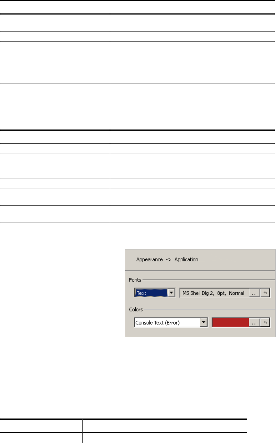
89 CHAPTER 3 Dialogs
Setting Description
Clear on reset
When set, the window’s text area is cleared follow-
ing each program reset.
Data limit Date limit, in KB, of the Terminal Window.
Zero-terminate input
When set, a string termination character (\0) is ap-
pended to terminal input before the input is sent to
the debuggee.
Echo input
When set, each terminal input is appended to the
terminal window’s text area.
Newline input termination format
Selects the type of line break to be appended to
terminal input before the input is send to the de-
buggee (see Newline Formats on page 262).
3.11.15.15 Timeline Window Settings
Setting Description
Cursor labels Selects the cursor labels to be displayed
Mouse wheel action
Selects the action to be performed when the mouse
wheel is scrolled (scroll time-axis, scroll Y-axis,
zoom time-axis, zoom Y-axis, none)
Time origin Selects the time origin (CPU halt, program start)
Auto scroll
Selects the auto-scrolling behavior(do not auto
scroll, auto scroll while program is running)
Clear event
Selects the debug event upon which the timeline is
cleared (see Clear Event).
3.11.15.16 Appearance Settings
On the appearance settings pages,
fonts and colors of a particular win-
dow or window group can be adjust-
ed. Within the window group “Appli-
cation”, the default appearance set-
tings for all windows and dialogs can
be specified.
Fonts
Lets users adjust individual fonts of the
window or window group.
Colors
Lets users adjust individual colors of
the window or window group.
3.11.15.17 Specifying User Preferences Programmatically
Each setting provided by the User Preference Dialog is affiliated with an user action. User
preference actions allow users to change the preference from a script function or at the
command prompt. The table below gives an overview of the available user preference ac-
tions.
User Preference Category Affiliated User Action(s)
General Settings Edit.Preference (see Edit.Preference on page 300)
Ozone User Guide & Reference Manual (UM08025) © 2013-2024 SEGGER Microcontroller GmbH


91 CHAPTER 3 Dialogs
3.11.16 Quick Find Widget
The Quick Find Widget is a pop-up screen that facilitates locating program symbols and
text patterns.
Quick Find Widget in text mode (left) and symbol mode (right).
How to use the quick find widget
As letters are typed into the input box, the list of match suggestions updates and shrinks.
The user selects the desired match via the arrow keys and upon pressing return, the se-
lected match will be shown and highlighted within its containing debug window.
3.11.16.1 Search Modes
The search mode of the Quick Find Widget can be selected using keyboard shortcuts or
the toolbar at the top.
Mode Hotkey Initial Match List Content
Find Text Ctrl+F All text lines of the active document.
Find Function Ctrl+M All functions.
Find Global Data Ctrl+J All global variables.
Find Source File Ctrl+K All source code files.
3.11.16.2 Text Search Options
When in text search mode, additional search options are provided via the toolbar below
the find text line:
Search Option Description
Match case The search is case sensitive.
Match whole word
Matching text must begin and end at word boundaries. This
setting is mutual exclusive with using wild cards and regular
expressions.
Use Unix Style Wildcards
The input text is interpreted as an expression containing
wildcards. This setting is mutual exclusive with matching
whole words and using regular expressions.
Use regular expression
The input text is interpreted as a regular expression. This
setting is mutual exclusive with matching whole words and
using wild cards.
Ozone User Guide & Reference Manual (UM08025) © 2013-2024 SEGGER Microcontroller GmbH

92 CHAPTER 3 Dialogs
Search Option Description
Include inline assembly
code
The search includes the active document’s inline assembly
code lines.
Furthermore, text search mode provides two buttons to toggle the “Matches” and “Current
Match” panes in the toolbar below the find text line.
Ozone User Guide & Reference Manual (UM08025) © 2013-2024 SEGGER Microcontroller GmbH

93 CHAPTER 3 Dialogs
3.11.17 Quick Watch Dialog
The Quick Watch Dialog enables users to observe the value of the expression under the
cursor (see Working With Expressions on page 201).
Quick Watch Dialog showing a symbol expression.
How to use the Quick Watch Dialog
The Quick Watch Dialog can be brought up by pressing hotkey Shift+F9 while the text
cursor is over the expression/symbol to be evaluated. A recently evaluated expression can
be select from the drop-down box. The values of symbols and member symbols can be
edited by double-clicking on a table row or by pressing spacebar.
3.11.17.1 Context Menu
The context menu of the Quick Watch Dialog provides options to select the display mode
of all or individual items. In addition, the context menu of the table header row enables
to toggle individual table columns.
Ozone User Guide & Reference Manual (UM08025) © 2013-2024 SEGGER Microcontroller GmbH

Chapter 4
Debug Information Windows
This chapter provides individual descriptions of Ozone’s debug information windows, start-
ing with the Breakpoint Window.
Ozone User Guide & Reference Manual (UM08025) © 2013-2024 SEGGER Microcontroller GmbH

95 CHAPTER 4 Breakpoints/Tracepoints Window
4.1 Breakpoints/Tracepoints Window
Ozone’s Breakpoints/Tracepoints Window lists all breakpoints, data breakpoints, tracepoints
and vector catches that have been set by the user during the current debug session.
Breakpoints window showing the state of breakpoints (top) and vector catches (bottom).
For reasons of simplicity, the terms breakpoint and tracepoint are used interchangeably
in this section.
4.1.1 Breakpoint Properties
The Breakpoint Window displays the following information about breakpoints:
Column Description
State Indicates if the breakpoint is enabled or disabled.
Type One of CODE, DATA, TRACE_START and TRACE_STOP.
Location Source code or instruction address location of the breakpoint.
Extras
Lists all advanced breakpoint properties that are set to non-default
values. Advanced breakpoint properties are summarized in Advanced
Breakpoint Properties on page 189 and Data Breakpoint Attributes
on page 191. Tracepoints do not carry advanced properties.
4.1.2 Breakpoint Dialog
The breakpoint dialog enables users to place break-
points on:
• Machine instructions
• Source lines
• Functions and other code symbols such as
assembly code labels
Source Line Input
Source code lines are specified in a predefined format
(see Source Code Location Descriptor on page 257).
Opening the Breakpoint Dialog
The Breakpoint Dialog can be accessed via the con-
Ozone User Guide & Reference Manual (UM08025) © 2013-2024 SEGGER Microcontroller GmbH

96 CHAPTER 4 Breakpoints/Tracepoints Window
text menu of the Breakpoint Window.
4.1.3 Derived Breakpoints
Source breakpoints can be expanded in order to reveal their derived instruction breakpoints.
4.1.4 Vector Catches
The list of supported vector catches and their states are shown within a
separate table of the Breakpoint Window (see title figure). The context
menu of this table hosts the following actions:
Set/Clear
Sets or clears the selected vector catch.
Clear All
Clears all vector catches.
Vector Catches
Shows or hides the vector catch table.
4.1.5 Context Menu
The Breakpoint Window’s context menu hosts
the following actions (see Breakpoint Actions
on page 282):
Clear
Clears the selected breakpoint.
Enable / Disable
Enables or disables the selected breakpoint.
Edit
Edits advanced properties of the selected
Breakpoint such as its trigger condition (see
Breakpoint Properties Dialog on page 62).
Show Source
Displays the source code line associated with
the selected breakpoint. This action can also be
triggered by double-clicking a table row.
Show Disassembly
Displays the assembly code line associated with
the selected breakpoint.
Set Breakpoint...
Opens the Breakpoint Dialog (see Breakpoint Dialog on page 95).
Set Data Breakpoint...
Opens the Data Breakpoint Dialog (see Data Breakpoint Dialog on page 66).
Ozone User Guide & Reference Manual (UM08025) © 2013-2024 SEGGER Microcontroller GmbH
97 CHAPTER 4 Breakpoints/Tracepoints Window
Set Tracepoint...
Opens the Tracepoint Dialog.
Enable All
Enables all breakpoints. The vector catches remain untouched.
Disable All
Disables all breakpoints. The vector catches remain untouched.
Clear All
Clears all breakpoints.
Filter Bar
Shows or hides the filter bar.
Vector Catches
Shows or hides the vector catch table.
Export
Opens a file dialog that enables users to export the table content to a CSV file. This action
can also be executed from the project script using command Window.Export.
4.1.6 Editing Breakpoints and Vector Catches Programmati-
cally
Ozone provides multiple user actions that allow users to edit breakpoints from script code
or from the command prompt (see Breakpoint Actions on page 282 and Trace Actions on
page 289).
User action Break.SetVectorCatch (see Break.SetVectorCatch on page 368) is provided to
set and clear vector catches within script functions or plugins.
4.1.7 Table Window
The Breakpoint Window shares multiple features with other table-based debug information
windows (see Table Windows on page 57).
Ozone User Guide & Reference Manual (UM08025) © 2013-2024 SEGGER Microcontroller GmbH

98 CHAPTER 4 Call Graph Window
4.2 Call Graph Window
Ozone’s Call Graph Window informs about function call paths and stack usages.
4.2.1 Overview
Each table row of the Call Graph Window provides information about a single function call.
The top-level rows of the call graph are populated with the program’s entry point functions.
Individual functions can be expanded in order to reveal their callees.
4.2.2 Setup
In order to obtain correct output when debugging applications that include custom instruc-
tions, a disassembly support plugin must have been loaded (see Project.SetDisassembly-
Plugin on page 334).
4.2.3 Table Columns
Name
Name of the function.
Stack Total
The maximum amount of stack space used by any call path that originates at the function,
including the function’s local stack usage.
Stack Local
The amount of stack space used exclusively by the function.
Code Total
The maximum code size of any call path that originates at the function, including the func-
tion’s local code size.
Code Local
The function’s code size, including code-inline data pools if present.
Ozone User Guide & Reference Manual (UM08025) © 2013-2024 SEGGER Microcontroller GmbH

99 CHAPTER 4 Call Graph Window
Depth
The maximum length of any non-recursive call path that originates at the function.
Called From
Source code location of the function call.
Call Site PC
Instruction memory location of the function call.
Note
Instruction-level information may not be accessible to Ozone before debug session
startup completion (see Startup Completion Point on page 186). Ozone will display
a warning sign next to table values which may be unavailable due to this reason.
4.2.4 Uncertain Values
A plus (+) sign that follows a table value indicates that the value is not exact but rather a
lower bound estimate of the true value. A trailing “R” or “FP” further indicates the reason
for the uncertainty. R stands for recursion and FP stands for function pointer call.
4.2.5 Recursive Call Paths
In order to obtain meaningful values for recursive call paths, the Call Graph Window only
evaluates these paths up to the point of recursion. This means that the total stack usage
and depth values obtained for recursive call paths are only lower bound estimates of the
true values (see Uncertain Values on page 99).
4.2.6 Function Pointer Calls
The Call Graph Window is able to detect function calls via function pointers. Currently, these
calls are restricted to be leaf nodes of the call graph. A function pointer call is indicated
by the display name “<fp-call>”.
4.2.7 Table Window
The Call Graph Window shares multiple features with other table-based debug information
windows provided by Ozone (see Table Windows on page 57).
4.2.8 Context Menu
Set/Clear Breakpoint
Sets or clears a breakpoint on the se-
lected function.
Show Call Site
Displays the call location of the select-
ed function within the Source Viewer
(see Source Viewer on page 155). This
action can also be triggered by dou-
ble-clicking a table row.
Show Implementation
Displays the implementation of the se-
Ozone User Guide & Reference Manual (UM08025) © 2013-2024 SEGGER Microcontroller GmbH
100 CHAPTER 4 Call Graph Window
lected function within the Source Viewer (see Source Viewer on page 155).
Show path with max stack usage
Expands all table rows on the call path with the highest stack usage.
Expand All / Collapse All
Expands or collapses all top-level entry point functions.
Group By Root Functions
Indicates if the top-level shows root functions only, i.e. functions that are not called by any
other functions. If unchecked, the top level shows all program functions.
Group Callees
Displays all calls made to the same function as a single table row.
Filter Bar / Total Value Bar
Toggles the named table header bar.
Export
Opens a file dialog that enables users to export the table content to a CSV file. This action
can also be executed from the project script using command Window.Export.
4.2.9 Call Graph Window Preferences
Section Call Graph Window Settings on page 86 lists all user preference settings pertaining
to the Call Graph Window.
Ozone User Guide & Reference Manual (UM08025) © 2013-2024 SEGGER Microcontroller GmbH

101 CHAPTER 4 Call Stack Window
4.3 Call Stack Window
Ozone’s Call Stack Window displays the function call sequence that led to the current pro-
gram execution point.
4.3.1 Overview
The topmost row of the Call Stack Window informs about the current program execution
point. Each of the other rows display information about a function call that led to the current
program execution point. In the illustration above, the second row informs about the call
site where function _FuncB called function _FuncC.
The preference “Callstack Layout” for the Call Stack Window allows to reverse the order of
rows such that the current program execution point is displayed at the bottom, not the top.
Changing that preference is also possible via the context menu of the call stack window.
4.3.2 Table Columns
The Call Stack Window provides the following information about function call sites:
Table Column Description
Function The calling function’s name.
Stack Info Size and position of the stack frame of the calling function.
Source Source code location of the function call.
PC Instruction address of the function call.
Return Address
PC that will be attained when the program returns from the function
call. This field is displayed as “location:value”, where “location” is the
target data location of the return address.
Note
A call site that the debugger cannot affiliate with a source code line is displayed as
the address of the machine instruction that caused the branch to the called function.
4.3.3 Call Site Parameter Values
The Call Stack Window may display the values and types of all local function parameters.
This settings can be toggled via the window’s context menu and via the preferences for
the Call Stack Window.
Ozone User Guide & Reference Manual (UM08025) © 2013-2024 SEGGER Microcontroller GmbH

102 CHAPTER 4 Call Stack Window
4.3.4 Instruction Based Call Stack Unwinding
The debug information found in the ELF file provides so called unwinding information which
describes where to find and how to interpret the information on the stack for finding the
sequence of function calls that led to the currently executing code. This debug information
also allows reconstruction of some of the register values that were valid inside a function.
The format of such unwinding information is documented in the DWARF standard.
Ozone uses that unwinding information for obtaining the sequence of function calls as well
as the values of parameters passed in each call.
In some ELF files the unwinding information is incomplete or missing. This may be caused
by having configured the build tool chain incorrectly. There are also build tool chains which
are incapable of creating the unwinding information according to the DWARF standard.
In case the unwinding information is missing in the ELF file, Ozone offers deriving the
unwinding information from an analysis of the instructions rather than from the ELF file.
This can be enabled via the system variable “Unwinding information source”.
The unwinding information in the ELF file normally contains information only for high-level
language code, not for assembly language. Therefore the call stack displayed in the call
stack window normally ends with the firsts function for which unwinding information is
available. For applications without an RTOS this may be the main function, for applications
incorporating an RTOS this is often a function inside the RTOS code.
Instruction analysis, however, is oblivious of an instruction being part of high-level language
code or assembly language code. Thus the analysis does not necessarily stop at main and
may stretch into the startup or RTOS code.
Call stack window operating on instruction analysis
For some branch instructions the destination address cannot be determined. If a function
call takes place in a code sequence that is reached only by such a branch instruction, the
call stack ends prematurely in that very place. Once the code execution leaves that code
sequence, the call stack is displayed correctly.
Note
As of now, instruction based call stack unwinding is available only for 16/32-bit ARM
architectures, it is not yet supported for RISC-V.
4.3.5 Unwinding Stop Reasons
The reason why call stack unwinding stopped is displayed at the bottom of the stack. Nor-
mally, the reason “Top of stack - no unwinding symbols at <Address>” indicates a complete
evaluation of the call stack. In case the system variable “Unwinding information source” is
set to “Instruction Analysis” a regular call stack evaluation ends with “Invalid return address
location: N/A”. The message “depth limit reached” is displayed if the number of call frames
displayed in the window exceeds the preference “Callstack Depth Limit” for the Call Stack
Window. In that case you may wish to increase the value for that preference.
Ozone User Guide & Reference Manual (UM08025) © 2013-2024 SEGGER Microcontroller GmbH

103 CHAPTER 4 Call Stack Window
Any other message indicates missing or erroneous unwinding information in the ELF file.
4.3.6 Active Call Frame
By selecting a table row within the Call Stack Window, the affiliated call frame becomes
the active program execution point context of the debugger. At this point, the Register and
Local Data Windows display content no longer for the current PC, but for the active call
frame. The active frame can be distinguished from the other frames in the call stack by the
preceding arrow dsiplayed left of the function name.
4.3.7 Context Menu
The Call Stack Windows’s context menu hosts ac-
tions that navigate to a call site’s source code or as-
sembly code line (see Show Actions on page 287).
Set/Clear Breakpoint
Sets or clears a breakpoint on the function of the
selected frame.
Show Source
Displays the selected call site within the Source
Viewer (see Source Viewer on page 155). This ac-
tion can also be triggered by double-clicking a table
row.
Show Disassembly
Displays the selected call site within the Dis-
assembly Window (see Disassembly Window on
page 117).
Show Stack Frame
Displays the base of the selected call frame with-
in the Memory Window (see Memory Window on page 135).
Parameter Names / Values / Types
Toggles the display of function parameter names / values / types.
Current Frame On Top
Selects the ordering of the frames on the call stack.
Filter Bar / Total Value Bar
Toggles the named table header bar.
Export
Opens a file dialog that enables users to export the table content to a CSV file. This action
can also be executed from the project script using command Window.Export.
4.3.8 Settings
The call stack window evaluates the following system variables settings:
System Variable Description
VAR_CALLSTACK_UNWIND_IN-
FO_SRC
Unwinding information is obtained from the ELF file
(“DWARF information”), by instruction analysis (“In-
Ozone User Guide & Reference Manual (UM08025) © 2013-2024 SEGGER Microcontroller GmbH

104 CHAPTER 4 Call Stack Window
System Variable Description
struction Analysis”), or the source is automatically
chosen (“Automatic”).
Section Call Stack Window Settings on page 86 lists all user preference settings pertaining
to the call stack window.
4.3.9 Table Window
The Call Stack Window shares multiple features with other table-based debug information
windows (see Table Windows on page 57).
Ozone User Guide & Reference Manual (UM08025) © 2013-2024 SEGGER Microcontroller GmbH

105 CHAPTER 4 Code Profile Window
4.4 Code Profile Window
Ozone’s Code Profile Window displays the program’s execution profile selectively at a file,
function, source line or instruction level.
4.4.1 Setup
Section Setting Up Trace on page 206 explains how to configure Ozone and the hardware
setup for trace, thereby enabling the Code Profile Window.
Note
Instruction-level information may not be accessible to Ozone before debug session
startup completion (see Startup Completion Point on page 186). Ozone will display
a warning sign next to table values which may be unavailable due to this reason.
4.4.2 Overview
Each table row displays the execution profile of a single program entity (PE). A program
entity is either a source file, a function, an executable source line or a machine instruction.
Table rows can be expanded to show their contained PEs. Table values continuously update
while the program is running.
4.4.3 Code Coverage
Code profile window displaying code coverage statistics.
Table columns code coverage and instruction coverage provide information about the pro-
gram’s code coverage.
Instruction Coverage
Percentage of machine instructions of the PE that have been covered since code profile data
was reset. A machine instruction is considered covered if it has been “fully” executed. In
the case of conditional instructions, “full execution” means that the condition was both met
and not met. In the title figure, 77.0% or 47 of 61 machine instructions within function
main were covered.
Ozone User Guide & Reference Manual (UM08025) © 2013-2024 SEGGER Microcontroller GmbH

106 CHAPTER 4 Code Profile Window
Source Coverage
Percentage of executable source code lines of the PE that have been covered since code
profile data was reset. An executable source code line is considered covered if all of its
machine instructions were fully executed. In the case of conditional instructions, “full exe-
cution” means that the condition was both met and not met. In the title figure, 66.7% or
6 of 9 executable source codes lines within function main were covered.
4.4.3.1 Color Bars
Table columns code coverage and instruction coverage display color bars to help identify
PE’s whose code can potentially be optimized.
A color bar is split vertically into a green (1), orange (2) and a white (3) segment. Each
segment visualizes a percentage value. The percentage values of all 3 segments add up
to 100.
Segment Source Coverage Instruction Coverage Prognosis
Percentage of source
lines that are fully cov-
ered. Identical to the
value displayed within
the table cell.
Percentage of instruc-
tions that are fully cov-
ered. Identical to the
value displayed within
the table cell.
Little to no potential for
optimization
Percentage of source
lines that are partially
covered
Percentage of instruc-
tions that are partially
covered
Good potential for opti-
mization
Percentage of source
lines that are not cov-
ered
Percentage of instruc-
tions that are not cov-
ered
Potential for removal
A source line or instruction is considered:
• fully covered, if its execution profile color code is solid-green
• partially covered, if its execution profile color code is orange or split orange-green
• not covered, if its execution profile color code is gray
Refer to Execution Profile Color-Codes on page 55.
4.4.4 Program Load
Table columns Run Count, Fetch Count and Load inform about the CPU usage of PE’s.
Run Count
Number of times the PE was executed since code profile data was reset.
Load
Number of instruction fetches that occurred within the PE’s address range divided by the
total number of instruction fetches that occurred since code profile data was reset.
Fetch Count
Number of instruction fetches that occurred within the address range of the PE.
Ozone User Guide & Reference Manual (UM08025) © 2013-2024 SEGGER Microcontroller GmbH

107 CHAPTER 4 Code Profile Window
Code profile window displaying PE load statistics.
4.4.5 Execution Counters
Ozone also shows the program’s execution profile inlined with the code. For more informa-
tion, refer to Code Profile Information on page 54.
4.4.6 Filters
Individual PE’s can be filtered from the code profile statistic. In particular, there are two
different type of filters that can be applied to PE’s, as described below.
Profile Filter
When a profile filter is set on a PE, its CPU load is filtered from the code profile statistic.
After filtering, the load column displays the distribution of the remaining CPU load across
all none-filtered PE’s.
Coverage Filter
When a coverage filter is set on a PE, its code coverage value is filtered from the code profile
statistic. After filtering, the code coverage columns displays coverage values computed as
if the filtered PE does not exist.
4.4.6.1 Adding and Removing Profile Filters
A profile filter can be set and removed via commands Profile.Exclude and Profile.Include
(see Code Profile Actions on page 282). In Addition, the load column of the Code Profile
Window provides a check box for each item that enables users to quickly set or unset the
filter on the item.
4.4.6.2 Adding and Removing Coverage Filters
A coverage filter can be set and removed via commands Coverage.Exclude and Cover-
age.Include (see Code Profile Actions on page 282). In Addition, the code coverage
columns of the Code Profile Window provide a check box for each item that enables users
to quickly set or unset the filter on the item.
4.4.6.3 Filtering Code Alignment Instructions
Compilers may place alignment instructions into program code that have no particular op-
eration and do never get executed. These so-called NOP-instructions can be filtered from
the code coverage statistic via context menu entry “Exclude All Trailing NOPs” or via com-
mand Coverage.ExcludeNOPs (see Coverage.ExcludeNOPs on page 348).
Ozone User Guide & Reference Manual (UM08025) © 2013-2024 SEGGER Microcontroller GmbH

108 CHAPTER 4 Code Profile Window
4.4.6.4 Observing the List of Active Filters
The Code Profile Filter Dialog can be accessed from the context menu and displays all filters
that were set, alongside the affiliated user action commands that were executed.
4.4.7 Context Menu
The context menu of the Code Pro-
file Window provides the following
actions:
Set/Clear Breakpoint
Sets or clears a breakpoint on the
selected function, source line or in-
struction.
Show Source
Displays the selected item with-
in the Source Viewer (see Source
Viewer on page 155).
Show Disassembly
Displays the selected item within
the Disassembly Window (see Dis-
assembly Window on page 117).
Include/Exclude from
Filters or unfilters the selected
item from the load, code coverage
or both statistics.
Exclude All Trailing NOPs
Excludes all “no operation” (code
alignment) instructions, which trail
the function’s code body, from the
code coverage statistic.
Exclude (Dialog)
Moves multiple items to the fil-
tered set (see Profile.Exclude on page 346).
Include (Dialog)
Removes multiple items from the filtered set (see Profile.Include on page 346).
Remove All Filters
Removes all filters.
Show Filters
Opens a dialog that displays an overview of the currently active filters.
Reset Execution Counters
Resets all execution counters (see Code Execution Counters on page 54).
Ozone User Guide & Reference Manual (UM08025) © 2013-2024 SEGGER Microcontroller GmbH
109 CHAPTER 4 Code Profile Window
Reset Data
Resets the session’s trace and sampling data. This action can also be executed from the
project script using command Timeline.Reset (see Timeline.Reset on page 355).
Execution Counters in Source
Displays execution counters within the Source Viewer (see Source Viewer on page 155).
Execution Counters in Disassembly
Displays execution counters within the Disassembly Window (see Disassembly Window on
page 117).
Group by Files
Groups all functions into expandable source file nodes.
Sort Respects Filters
When this option is checked, filtered items are moved to the bottom of the table.
Parent Relative Load
When this option is checked, the CPU load of a table item is calculated as the total number of
instructions executed within the item divided by the total number of instructions executed
within the parent item. Otherwise, the total number of instructions executed is used as
the divisor.
Filter Bar / Total Value Bar
Toggles the named table header bar.
Export
Opens a file dialog that enables users to export the table content to a CSV file. This action
can also be executed from the project script using command Window.Export.
4.4.8 User Preference Settings
The User Preference Dialog allows users to specify appearance-related settings of the Code
Profile Window. The available settings are listed in section Code Profile Window Settings
on page 86.
4.4.9 Selective Tracing
Ozone can instruct the target to constrain trace data output to individual address ranges
(see Tracepoints on page 208). When selective tracing is active, it acts as a hardware
prefilter of code profile data.
4.4.10 Table Window
The Code Profile Window shares multiple features with other table-based debug information
windows (see Table Windows on page 57).
Ozone User Guide & Reference Manual (UM08025) © 2013-2024 SEGGER Microcontroller GmbH

110 CHAPTER 4 Console Window
4.5 Console Window
Ozone’s Console Window displays application- and user-induced messages.
4.5.1 Command Prompt
The Console Window displays a command prompt below its text area that enables users to
execute any user action that has a command (see User Actions on page 42). It is possible
to control the debugger from the command prompt alone.
4.5.2 Message Types
The type of a console message depends on its origin. There are three different message
sources and hence there are three different message types. The message types are de-
scribed below.
4.5.2.1 Command Feedback Messages
When a user action is executed − be it via the Console Window’s command prompt or any of
the other ways described in Executing User Actions on page 42 − the action’s command text
is added to the Console Window. This process is termed command feedback. For actions
that query a value, the returned value is displayed in a trailing comment.
Target.GetReg("PC"); // returns 0x8000284
4.5.2.2 Error Messages
When an unexpected condition occurs and depending on the severity of the condition, an
error or warning message is logged to the Console Window. Most error and warning mes-
sages are accompanied by a message code. The message code is an index into table Errors
and Warnings on page 275, which provides additional information about the exception.
Target.GetReg("ProgramCounter"): unknown register "ProgramCounter".
4.5.2.3 J-Link/J-Trace Messages
Control and status messages emitted by the debug probe API are a distinct message type.
J-Link: Device STM32F13ZE selected.
4.5.2.4 Script Messages
Messages emitted from script functions are a distinct message type.
Executing Script Function "BeforeTargetConnect".
The commands Util.Log (see Util.Log on page 313) and TargetInterface.message (see Tar-
getInterface.message on page 381) can be employed within project scripts and JavaScript
plugins, respectively, to log a message to the Console Window. Command Util.Error (see
Ozone User Guide & Reference Manual (UM08025) © 2013-2024 SEGGER Microcontroller GmbH

111 CHAPTER 4 Console Window
Util.Error on page 313) is provided to display an error message box and stop the debug
session.
4.5.3 Message Colors
Messages printed to the Console Window are colored according to their type.
The message colors can be adjusted via command Edit.Color (see Edit.Color on page 301)
or via the User Preference Dialog (see User Preference Dialog on page 85). The default
coloring scheme is depicted above.
4.5.4 Context Menu
The context menu of the Console Window provides the fol-
lowing actions:
Copy
Copies the selected text to the clipboard.
Select All
Selects all text lines.
Clear
Clears the Console Window.
List Commands
Prints the command help.
Timestamps
Toggles the display of message timestamps.
Export
Opens a file dialog that enables users to export the content of the console window to a CSV
file. This action can also be executed from the project script using command Window.Export.
4.5.5 Command Help
When command Help.Commands is executed, a quick facts table on all user actions in-
cluding their commands, hotkeys, and purposes is printed to the Console Window (see
Help.Commands on page 330). The command help can be triggered from the Console
Window’s context menu or from the main menu (Help → Commands).
Ozone User Guide & Reference Manual (UM08025) © 2013-2024 SEGGER Microcontroller GmbH

112 CHAPTER 4 Console Window
Command help displayed within the Console Window
4.5.6 Console Window Preferences
Section Console Window Settings on page 87 lists all user preference settings pertaining
to the Console Window.
Ozone User Guide & Reference Manual (UM08025) © 2013-2024 SEGGER Microcontroller GmbH
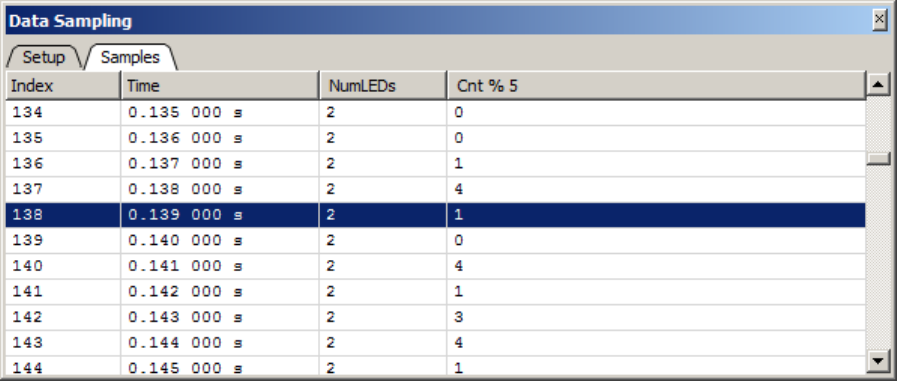
113 CHAPTER 4 Data Sampling Window
4.6 Data Sampling Window
Ozone’s Data Sampling Window employs SEGGER’s High-Speed Sampling (HSS) API to
trace the values of user-defined expressions at time resolutions of down to 100 us (see
Working With Expressions on page 201 and J-Link User Guide ).
4.6.1 Hardware Requirements
The Data Sampling Window requires the target to support background memory access
(BMA) for best performance.
J-Link/J-Trace is also capable of emulating BMA on most targets, with a small performance
penalty over hardware BMA.
Ozone system variable VAR_ALLOW_BMA_EMULATION controls if BMA emulation is to auto-
matically take effect when hardware support is not present.
4.6.2 Sampling Frequency
The sampling request of all expressions that are added to the Data Sampling Window is sent
to the debug probe at the same time. This common sampling frequency can be adjusted via
the context menu or via command Edit.SysVar using argument VAR_HSS_SPEED. A sampling
frequency of 0 disables data sampling.
The sampling frequency can be assigned persistently to the project by placing its command
into project script function OnProjectLoad.
The sampling of expressions starts automatically each time the program is resumed and
stops automatically each time the program halts.
4.6.3 Data Limit
User preference PREF_DATA_SAMPLING_DATA_LIMIT sets the data limit of the data sampling
window. The default data limit is 16MB. When the data limit is reached, data acquisition
will continue but the oldest data will be overwritten.
4.6.4 Window Layout
The Data Sampling Window provides two content panes − or views − which can be switched
by selecting the corresponding tab within the tab bar.
Ozone User Guide & Reference Manual (UM08025) © 2013-2024 SEGGER Microcontroller GmbH

114 CHAPTER 4 Data Sampling Window
4.6.5 Setup View
The Setup View enables users to assemble the list of expressions whose values are to be
traced while the program is running. An expression can be added to the list in any of the
following ways:
• via context menu entry Add Expression.
• via command Window.Add (see Window.Add on page 308).
• via the last table row that acts as an input field.
• by dragging a symbol from a symbol window or the Source Viewer onto the Setup View.
and removed from the list via:
• context menu entry Remove.
• command Window.Remove (see Window.Remove on page 309).
A traced expression must satisfy the following constraints:
• the expression must evaluate to a numeric value of size less or equal to 8 bytes.
• all symbol operands of the expression must be either static variables or constants.
Setup view of the Data Sampling Window.
The setup view’s toolbar provides quick access to the sample frequency. The toolbar can
be shown and hidden via the context menu entry “Toolbar”. If this entry is checked, the
toolbar is shown, if it is unchecked, the toolbar is hidden.
4.6.5.1 Signal Statistics
Next to its editing functionality, the Setup View provides basic signal statistics for each
traced expression. The meanings of the displayed values are explained below.
Min, Max, Average
Minimum, maximum and average signal values.
#Changes
The number of times the signal value has changed between two consecutive samples.
Min. Change
The largest negative change between two consecutive samples of the symbol value.
Max. Change
The largest positive change between two consecutive samples of the symbol value.
4.6.5.2 Context Menu
The context menu of the Setup View provides the following actions:
Remove
Removes an expression from the window.
Display (All) As
Allows users to change the display format of the selected expression or all expressions.
Ozone User Guide & Reference Manual (UM08025) © 2013-2024 SEGGER Microcontroller GmbH

115 CHAPTER 4 Data Sampling Window
Sampling Frequency
Selects the data sampling frequency.
Add Expression
Opens an input box that lets users add an expression to the window.
Remove All
Removes all expression from the window.
Reset Data
Resets the session’s trace and sampling da-
ta. This action can also be executed from the
project script using command Timeline.Reset
(see Timeline.Reset on page 355).
Toolbar
Toggles the display of the toolbar.
Filter Bar / Total Value Bar
Toggles the named table header bar.
Export
Opens a file dialog that enables users to export
the table content to a CSV file. This action can
also be executed from the project script using command Window.Export.
4.6.6 Samples View
The Samples View displays the sampling data in a tabular fashion. Following two columns
that displays the index and time stamp of a sample, the remaining columns display the
values of each traced expression at the time the sample was taken.
The samples view’s toolbar provides quick access to the sample frequency. The toolbar can
be shown and hidden via the context menu entry “Toolbar”. If this entry is checked, the
toolbar is shown, if it is unchecked, the toolbar is hidden.
4.6.6.1 Context Menu
The context menu of the Samples View provides the follow-
ing actions:
Sampling Frequency
Selects the data sampling frequency.
Goto Time
Opens an input dialog that enables users to scroll to a par-
ticular samples table row.
Export
Opens a file dialog that enables users to export the sampling data to a CSV file. This action
can also be executed from the project script using command Export.DataGraphs.
Toolbar
Toggles the toolbar.
Ozone User Guide & Reference Manual (UM08025) © 2013-2024 SEGGER Microcontroller GmbH
116 CHAPTER 4 Data Sampling Window
4.6.7 Timeline
HSS sampling data, together with power and instruction trace data, is visualized in a com-
bined signal plot (see Timeline Window on page 164). This enables users to establish a
link between the values of selected variables and program execution. To further support
this correspondence, the selected table row of the Data Sampling Window is synchronized
with the sample cursor of the Timeline Window.
4.6.8 Data Sampling Window Preferences
Section Data Sampling Window Settings on page 87 lists all user preference settings per-
taining to the Data Sampling Window.
Ozone User Guide & Reference Manual (UM08025) © 2013-2024 SEGGER Microcontroller GmbH

117 CHAPTER 4 Disassembly Window
4.7 Disassembly Window
Ozone’s Disassembly Window displays the assembly code interpretation of target memory.
The window automatically scrolls to the position of the program counter when the program
is stepped; this enables users to follow program execution on the machine instruction level.
4.7.1 Assembly Code
Each standard text line of the Disassembly Window displays information about a particular
machine instruction. The instruction information is divided into 4 parts:
Address Encoding Mnemonic Operand
0800297C B538 PUSH {R3-R5,LR}
Instruction Encoding
The encoding of a machine instruction is identical to the data stored at the instruction’s
memory address. It is possible to toggle the display of instruction encodings via the context
menu or permanently via the User Preference Dialog (see Disassembly Window Settings
on page 87).
Syntax Highlighting
The Disassembly Window applies syntax highlighting to assembly code. The syntax high-
lighting colors can be adjusted via command Edit.Color (see Edit.Color on page 301) or
via the User Preference Dialog (see User Preference Dialog on page 85).
4.7.2 Execution Counters
The Disassembly Window may show the execution counts of individual instructions within
its left sidebar area (see Code Execution Counters on page 54).
4.7.3 Key Bindings
The disassembly window’s special-purpose key bindings are:
Hotkey Description
Enter Navigates to the target address of the selected instruction.
Space Show the selected instruction within the Source Viewer.
Alt+Left Returns to the previous waypoint.
Alt+Right Shows the next waypoint.
Ozone User Guide & Reference Manual (UM08025) © 2013-2024 SEGGER Microcontroller GmbH

118 CHAPTER 4 Disassembly Window
Next to these keyboard shortcuts, the disassembly window also supports the standard
hotkeys provided by debug windows (see Standard Shortcuts on page 51) and code win-
dows {see Text Cursor Navigation Shortcuts on page 55}.
4.7.4 Context Menu
The Disassembly Window’s context menu provides the
following actions:
Quick Watch
Opens the Quick Find Widget (see Quick Find Widget
on page 91) for the text selection or word under the
cursor.
Set/Clear/Edit Breakpoint
Sets/Clears or Edits a breakpoint on the selected
machine instruction (see Instruction Breakpoints on
page 189).
Set Tracepoint (Start/Stop)
Sets a tracepoint on the selected machine instruction
(see Tracepoints on page 208).
Set Next PC
Specifies that the selected machine instruction should
be executed next. Any instructions that would usually
execute when advancing the program to the selected
instruction will be skipped.
Run To Cursor
Advances the program execution point to the current
cursor position. All code between the current PC and
the cursor position is executed.
Show Definition
Jumps to the source code definition location of the sym-
bol under the cursor.
Show Declaration
Jumps to the source code declaration location of the
symbol under the cursor.
Show Source
Displays the first source code line that is associated with the selected machine instruction
(as a result of code optimization during the compilation phase, a single machine instruction
might be affiliated with multiple source code lines).
Show Data
Displays the selected data item within the Memory Window (see Memory Window on
page 135).
Show Target Address
Navigates to the target address of the selected instruction.
Ozone User Guide & Reference Manual (UM08025) © 2013-2024 SEGGER Microcontroller GmbH
119 CHAPTER 4 Disassembly Window
Goto PC
Scrolls the viewport to the PC line.
Go Back
Returns to the previous waypoint.
Go Forward
Shows the next waypoint.
Go To
Sets the viewport to an arbitrary memory address. The address is obtained via an input
dialog that pops up when executing this menu item.
Set Plugin
Sets the disassembly plugin to be used with the current project (see Disassembly Plugin
on page 119).
Edit Plugin
Opens the script file of the loaded disassembly plugin within the Source Viewer.
Reload Plugin
Reloads the disassembly plugin.
Source Lines
Toggles the display of source lines.
Labels
Toggles the display of assembly labels.
Execution Counters
Toggles the display of Code Execution Counters (see Code Execution Counters on page 54).
Instruction Encodings
Toggles the display of instruction encodings.
Pseudo Instructions
Enables or disables pseudo-instruction display.
Find In Trace
Opens the Find In Trace Dialog with the word under the cursor (see Find In Trace Dialog
on page 71).
Export
Opens the Disassembly Export Dialog (see Disassembly Export Dialog on page 67).
4.7.5 Disassembly Plugin
The disassembly window can be extended to include the assembly code and code profiling
information of custom instructions (see Disassembly Plugin on page 119). A disassembly
plugin can be assigned to the project via context menu action Set Plugin or command
Project.SetDisassemblyPlugin.
Ozone User Guide & Reference Manual (UM08025) © 2013-2024 SEGGER Microcontroller GmbH
120 CHAPTER 4 Disassembly Window
4.7.6 Offline Disassembly
The disassembly window is functional even when Ozone is not connected to the target. In
this case, machine instruction data is read from the program file. In fact, disassembly is
only performed on target memory when the program file does not provided data for the
requested address range.
4.7.7 Code Window
The Disassembly Window shares multiple features with Ozone’s second code window, the
Source Viewer. Refer to Code Windows (see Code Windows on page 52) for a shared de-
scription of these windows.
4.7.8 Disassembler Options
Command Project.ConfigDisassembly (see Project.ConfigDisassembly on page 345) is pro-
vided to control behavioral aspects of the disassembler.
4.7.9 Appearance Settings
Section Disassembly Window Settings on page 87 lists all appearance-related settings per-
taining to the disassembly window.
Ozone User Guide & Reference Manual (UM08025) © 2013-2024 SEGGER Microcontroller GmbH

121 CHAPTER 4 Find Results Window
4.8 Find Results Window
Ozone’s Find Results Window displays the results of previous text searches.
Find Results Window displaying the results of a text search within the Instruction Trace
Window.
4.8.1 Find Result Tabs
The Find Results Window adds a result tab for each text search that was performed. The
result of the text search is displayed as a list of text lines that matched the search pattern.
The search settings are displayed in the first row of the search result text. Tabs can be
closed and rearranged freely.
4.8.2 Supported Text Search Locations
Text searches are currently supported in the following locations:
• Source code documents
• Instruction Trace Window contents
A new text search is performed using the:
• Find In Files Dialog or
• Find In Trace Dialog
4.8.3 Match Highlighting
By double-clicking on a table row or by pressing Return, the match is selected within the
Source Viewer or Instruction Trace Window.
4.8.4 Context Menu
The Find Results Window’s context menu provides the
following actions:
Copy
Copies the selected text to the clipboard.
Clear
Clears the match list.
Ozone User Guide & Reference Manual (UM08025) © 2013-2024 SEGGER Microcontroller GmbH
122 CHAPTER 4 Find Results Window
Show Source
Shows the selected match within the Source Viewer. Can also be performed by double-click-
ing on a match result.
Show Next Result
Displays the next match within the Source Viewer.
Show Previous Result
Displays the previous match within the Source Viewer.
Ozone User Guide & Reference Manual (UM08025) © 2013-2024 SEGGER Microcontroller GmbH

123 CHAPTER 4 Functions Window
4.9 Functions Window
Ozone’s Functions Window lists all functions linked to assemble the debuggee, including
external library functions.
Note
When a function is missing from the Functions Window, it was not linked into the
executable image of the debuggee. This is in most cases the result of a compiler/linker
optimization.
4.9.1 Function Properties
The Functions Window displays the following information about functions:
Table Column Description
Name Name of the function.
Address base address of the function’s machine code.
Size Byte size of the function’s machine code.
#Insts Number of instructions encompassed by the function.
Source Source code implementation location of the function.
#Insts: instruction-level information may not be accessible to Ozone before debug session
startup completion (see Startup Completion Point on page 186). Ozone will display a
warning sign next to table values which may be unavailable due to this reason (see the
title figure).
4.9.2 Inline Expanded Functions
A function that is inline expanded in one or multiple other functions can be expanded and
collapsed within the Functions Window to show or hide its expansion sites. As an example,
consider the figure above. Function _TestWhile is inline-expanded within within functions
main and TimelineTest.
Ozone User Guide & Reference Manual (UM08025) © 2013-2024 SEGGER Microcontroller GmbH

124 CHAPTER 4 Functions Window
4.9.3 Context Menu
The Function Windows’ context menu hosts actions that navigate to a function’s source
code or assembly code line (see Show Actions on page 287).
Set Clear Breakpoint
Sets or clears a breakpoint on the function’s first machine instruction.
Show Source
Displays the first source code line of the selected function within the Source Viewer (see
Source Viewer on page 155). If an inline expansion site is selected, this site is shown
instead.
Show Disassembly
Displays the first machine instruction of the se-
lected function within the Disassembly Window
(see Disassembly Window on page 117). If an
inline expansion site is selected, this site’s first
machine instruction is displayed instead.
Show Call Graph
Displays the call graph of the function within the
Call Graph Window (see Call Graph Window on
page 98).
Show In Memory Map
Displays the function symbol within the Memory
Usage Window (see Memory Usage Window on page 139).
Filter Bar / Total Value Bar
Toggles the named table header bar.
Export
Opens a file dialog that enables users to export the table content to a CSV file. This action
can also be executed from the project script using command Window.Export.
4.9.4 Breakpoint Indicators
A breakpoint icon proceeding a function name indicates that one or multiple breakpoints
are set within the function’s address range.
4.9.5 Function Display Names
The display of function names can be configured via the following user preferences (see
User Preference Dialog on page 85):
User Preference Description
PREF_SHOW_FUNC_TYPE_SIGNATURES Append the type signature to the function name.
PREF_PREFIX_FUNC_CLASS_NAMES
Prepend the class name to C++ member function
names.
The above settings apply to the functions window and to all GUI elements that display
function names. This includes debug windows, export dialogs and drop-down lists.
Ozone User Guide & Reference Manual (UM08025) © 2013-2024 SEGGER Microcontroller GmbH

126 CHAPTER 4 Global Data Window
4.10 Global Data Window
Ozone’s Global Data Window displays the list of global program variables used by the de-
buggee.
Note
When a variable is missing from the Global Data Window, it was not linked into the
data image of the debuggee. This is in most cases the result of a compiler/linker
optimization.
4.10.1 Table Window
The Global Data Window shares multiple features with other table-based debug information
windows provided by Ozone (see Table Windows on page 57).
4.10.2 Data Breakpoint Indicator
A breakpoint icon preceding a global variable’s name indicates that a data breakpoint is
set on the variable.
4.10.3 Context Menu
The Global Data Window’s context menu provides the following actions:
Set/Clear/Edit Data Breakpoint
Sets/clears/edits a data breakpoint on the selected global variable (see Data Breakpoints
on page 191).
Watch
Adds the selected global variable to the Watched Data Window.
Quick Watch
Shows the selected global variable within the Quick Watch Dialog.
Ozone User Guide & Reference Manual (UM08025) © 2013-2024 SEGGER Microcontroller GmbH

127 CHAPTER 4 Global Data Window
Graph
Adds the selected global variable to the Data Sampling Window.
Show Value in Source
Displays the source code declaration location of the symbol pointed to within the Source
Viewer. Only shown for pointer-type variables.
Show Value in Disassembly
Displays the disassembly location of the sym-
bol pointed to within the Disassembly Win-
dow. Only shown for pointer-type variables.
Show Value in Data
Displays the memory location of the symbol
pointed to within the Memory Window. Only
shown for pointer-type variables.
Show Source
Displays the source code declaration loca-
tion of the selected global variable within
the Source Viewer (see Source Viewer on
page 155).
Show Data
Displays the data location of the selected lo-
cal variable in either the Memory Window
(see Memory Window on page 135) or the
Registers Window (see Registers Window on
page 147).
Show In Memory Map
Displays the data location of the select-
ed local variable within the Memory Usage Window (see Memory Usage Window on
page 139).
Display (All) As
Changes the display format of the selected global variable or of all global variables (see
Display Format on page 57).
Expand / Collapse All
Expands or collapses all top-level nodes.
Member Functions
Toggles the display of class member functions.
Filter Bar / Total Value Bar
Toggles the named table header bar.
Export
Opens a file dialog that enables users to export the table content to a CSV file. This action
can also be executed from the project script using command Window.Export.
Ozone User Guide & Reference Manual (UM08025) © 2013-2024 SEGGER Microcontroller GmbH

128 CHAPTER 4 Instruction Trace Window
4.11 Instruction Trace Window
Ozone’s Instruction Trace Window displays the history of executed machine instructions.
4.11.1 Setup
Section Setting Up Trace on page 206 explains how to configure Ozone and the hardware
setup for trace, thereby enabling the Instruction Trace Window.
4.11.2 Instruction Row
The information displayed within a single text line of the Instruction Trace Window is par-
titioned in the following way:
Timestamp Address Encoding Mnemonic Operands
0.000 100 005 0800297C B538 PUSH {R3-R5,LR}
4.11.3 Instruction Stack
The Instruction Trace Window displays the program’s instruction execution history as a
stack of machine instructions. The instruction at the bottom of the stack has been executed
most recently. The instruction at the top of the stack was executed least recently.
4.11.4 Trace Blocks
The instruction stack is partitioned into trace blocks. A trace block contains the instructions
that were executed between two consecutive program halt events. Each time the target
halts on a new PC, an additional trace block is appended to the bottom of the instructions
stack.
Ozone User Guide & Reference Manual (UM08025) © 2013-2024 SEGGER Microcontroller GmbH

129 CHAPTER 4 Instruction Trace Window
A trace block may not contain all instructions that were executed between two consecutive
halt events. This may be due to hardware limitations, such as a finite trace buffer capacity,
or due to the software limit opposed by VAR_TRACE_MAX_INST_CNT. As a result, trace blocks
may be disconnected.
Each trace block has got a header bar which acts as a visual separator between trace blocks.
The trace block header informs about the debug event that caused the program to halt and
also informs about the debug event that caused the program to resume.
4.11.5 Call Frames
A trace block is partitioned into a set of call frames. Each call frame contains the set of
instructions that were executed between entry to and exit from a program function. Call
frames can be collapsed or expanded to hide or reveal the affiliated instructions.
The header of a call frame informs about the function name, the number of instructions
executed and the total CPU time spend in the call frame.
4.11.6 Backtrace Highlighting
Both code windows highlight the instruction that is selected within the Instruction Trace
Window. This enables users to quickly understand past program flow while key-navigating
through instruction rows. The default color used for backtrace highlighting is yellow and can
be adjusted via command Edit.Color (see Edit.Color on page 301) or via the User Prefer-
ence Dialog (see User Preference Dialog on page 85). The backtrace highlighting feature
can be toggled via the User Preference Dialog or via the context menu of the Instruction
Trace Window.
4.11.7 Text Search
Ozone provides the Find In Trace Dialog to perform text pattern searches within the data
contents of the Instruction Trace Window.
Ozone User Guide & Reference Manual (UM08025) © 2013-2024 SEGGER Microcontroller GmbH

130 CHAPTER 4 Instruction Trace Window
4.11.8 Key Bindings
The table below provides an overview of the Instruction Trace Window’s special-purpose
key bindings.
Hotkey Description
+ Expands the selected call frame.
− Collapses the selected call frame.
Alt+Up Selects and scroll to the first (topmost) instruction of the call frame.
Alt+Down
Selects and scroll to the last (bottommost) instruction of the call
frame.
Alt+Home Selects and scroll to the first (topmost) instruction of the trace block.
Alt+End
Selects and scroll to the last (bottommost) instruction of the trace
block.
Next to these keyboard shortcuts, the Instruction Trace Window also supports the standard
hotkeys provided by debug windows (see Standard Shortcuts on page 51) and code win-
dows {see Text Cursor Navigation Shortcuts on page 55}.
4.11.9 Context Menu
The context menu of the Instruction Trace Window provides the following operations:
Copy
Copies the selected text to the clipboard.
Set / Clear Breakpoint
Sets or clears a breakpoint on the selected in-
struction.
Set Tracepoint (Start/Stop)
Sets a tracepoint on the selected machine instruc-
tion (see Tracepoints on page 208).
Show Source
Displays the source code line associated with the
selected instruction in the Source Viewer (see
Source Viewer on page 155)
Show Disassembly
Displays the selected instruction in the Disas-
sembly Window (see Disassembly Window on
page 117)
Toggle Reference
Toggles the time reference point on the selected
instruction.
Clear All References
Clears all time reference points
Go To Reference
Scrolls to the time reference point preceding the
Ozone User Guide & Reference Manual (UM08025) © 2013-2024 SEGGER Microcontroller GmbH
131 CHAPTER 4 Instruction Trace Window
selected instruction.
First in Function
Scrolls to the least recent instruction of the selected call frame.
Last in Function
Scrolls to the most recent instruction of the selected call frame.
First in Trace Block
Scrolls to the least recent instruction of the current trace block.
Last in Trace Block
Scrolls to the most recent instruction of the current trace block.
Expand/Collapse All
Expands/Collapses all call frame.
Instruction Encodings
Toggles the display of instruction encodings.
Timestamps
Selects the time stamp format (see Trace Timestamp Formats on page 262).
Reset Data
Resets the session’s trace and sampling data. This action can also be executed from the
project script using command Timeline.Reset (see Timeline.Reset on page 355).
Find In Trace
Opens the Find In Trace Dialog with the word under the cursor (see Find In Trace Dialog
on page 71).
Export
Opens a dialog that enables users to export the window contents to a CSV file. This action
can also be executed from the project script using command Export.Trace.
4.11.10 Instruction Trace Window Preferences
Section Instruction Trace Window Settings on page 87 lists all user preference settings
pertaining to the Instruction Trace Window.
4.11.11 Selective Tracing
Ozone can instruct the target to constrain trace data output to individual address ranges
(see Tracepoints on page 208). When selective tracing is active, it acts as a hardware
prefilter of trace data.
4.11.12 Limitations
The Instruction Trace Window currently cannot be used in conjunction with the Terminal
Window’s printf via SWO feature.
Ozone User Guide & Reference Manual (UM08025) © 2013-2024 SEGGER Microcontroller GmbH

132 CHAPTER 4 Local Data Window
4.12 Local Data Window
Ozone’s Local Data Window displays local variables and function parameters.
4.12.1 Overview
The Local Data Window enables users to inspect the local variables of any function on the
call stack. To change the Local Data Window’s output to an arbitrary function on the call
stack, the function must be selected within the Source Viewer or the Call Stack Window.
Once the program is stepped, the output will switch back to the current function.
4.12.2 Auto Mode
The Local Data Window provides an “auto mode” display option; when this option is active,
the window displays all global variables referenced within the current function alongside
the function’s local variables. Auto mode is inactive by default and can be toggled from
the window’s context menu.
4.12.3 Data Breakpoint Indicator
A breakpoint icon preceding a local variable’s name indicates that a data breakpoint is set
on the variable.
4.12.4 Context Menu
The Local Data Window’s context menu provides the following actions:
Set/Clear/Edit Data Breakpoint
Sets/clears/edits a data breakpoint on the selected symbol (see Data Breakpoints on
page 191).
Watch
Adds the selected local variable to the Watched Data Window (see Watched Data Window
on page 175).
Ozone User Guide & Reference Manual (UM08025) © 2013-2024 SEGGER Microcontroller GmbH

133 CHAPTER 4 Local Data Window
Quick Watch
Shows the selected local variable within the Quick Watch Dialog (see Quick Watch Dialog
on page 93).
Graph
Adds the selected local variable to the Data Sampling Window (see Data Sampling Window
on page 113).
Show Value in Source
Displays the source code declaration location
of the symbol pointed to within the Source
Viewer. Only shown for pointer-type vari-
ables.
Show Value in Disassembly
Displays the disassembly location of the sym-
bol pointed to within the Disassembly Win-
dow. Only shown for pointer-type variables.
Show Value in Data
Displays the memory location of the symbol
pointed to within the Memory Window. Only
shown for pointer-type variables.
Show Source
Displays the source code declaration location
of the selected local variable in the Source
Viewer (see Source Viewer on page 155).
Show Data
Displays the data location of the selected lo-
cal variable in either the Memory Window
(see Memory Window on page 135) or the
Registers Window (see Registers Window on
page 147).
Display (All) As
Changes the display format of the selected symbol or of all symbols (see Display Format
on page 57).
Expand / Collapse All
Expands or collapses all top-level nodes.
Member Functions
Toggles the display of class member functions. This item is only visible when the debuggee’s
source language is C++.
Auto Mode
Specifies whether the “auto mode” display option is active (see Auto Mode on page 132).
Filter Bar / Total Value Bar
Toggles the named table header bar.
Ozone User Guide & Reference Manual (UM08025) © 2013-2024 SEGGER Microcontroller GmbH
134 CHAPTER 4 Local Data Window
Export
Opens a file dialog that enables users to export the table content to a CSV file. This action
can also be executed from the project script using command Window.Export.
4.12.5 Table Window
The Local Data Window shares multiple features with other table-based debug information
windows provided by Ozone (see Table Windows on page 57).
Ozone User Guide & Reference Manual (UM08025) © 2013-2024 SEGGER Microcontroller GmbH

135 CHAPTER 4 Memory Window
4.13 Memory Window
Ozone’s Memory Window enables users to observe and edit target memory content.
4.13.1 Window Layout
The memory window displays target memory content using the following layout:
Address Section
The data column on the left side of the Memory Window displays the row’s start address.
Hex Section
The central data column displays memory content as hexadecimal values. The value block
size can be adjusted to 1, 2 or 4 bytes. In the illustration above, the display mode is set
to 2 bytes per block value.
Text Section
The data column on the right side of the Memory Window displays the textual interpretation
(Latin1-decoding) of target memory data.
4.13.2 Base Address
The address of the first byte displayed within the Memory Window is referred to as the
window’s base address.
4.13.2.1 Setting the Base Address
The base address of the Memory Window can be set in any of the following ways:
• via command Show.Data.
• via the goto-dialog accessible from the context menu.
• via the toolbar’s input box.
In each case, the following input formats are understood:
Input Format Example
Address 0x20000000
Address range 0x20000000, 0x200
Symbol OS_Global
Ozone User Guide & Reference Manual (UM08025) © 2013-2024 SEGGER Microcontroller GmbH

136 CHAPTER 4 Memory Window
Input Format Example
Register Name SP
Expression OS_Global->pTask + 0x4
For details on supported expressions, see Working With Expressions on page 201. When
the base address input has a deducible byte size, the corresponding address range is se-
lected and highlighted.
4.13.3 Drag & Drop
The Memory Window accepts drops of symbol/register names. When an item is dropped
onto the window, the item’s address range is highlighted and scrolled into view.
4.13.4 Toolbar
The Memory Window’s toolbar provides quick access to the window’s options. All toolbar
actions can also be accessed via the window’s context menu.
The toolbar can be shown and hidden via the context menu entry “Toolbar”. If this entry is
checked, the toolbar is shown, if it is unchecked, the toolbar is hidden.
The toolbar elements are described below.
Address Box
The toolbar’s address box provides a quick way of modifying the base address, i.e. the
memory address of the first byte that is displayed within the Memory Window. When a
pointer expression is input into the address box, the Memory Window automatically scrolls
to the address pointed to each time it changes.
Access Width
The blue tool buttons allow users to specify the memory access width. The access width
determines whether memory is accessed in chunks of bytes (access width 1), half words
(access width 2) or words (access width 4).
Display Mode
The red tool buttons let users choose the display mode. There are three display modes that
correspond to the byte size of each hexadecimal value displayed within the hex section.
The display mode can be set to 1, 2 or 4 bytes per value.
Fill Memory
Opens the Fill Memory Dialog (see Memory Dialog on page 73)
Save Memory Data
Opens the Save Memory Dialog (see Memory Dialog on page 73)
Load Memory Data
Opens the Load Memory Dialog (see Memory Dialog on page 73)
Periodic Refresh
Specifies the periodic refresh interval while the program is running (see Periodic Update
on page 137).
Ozone User Guide & Reference Manual (UM08025) © 2013-2024 SEGGER Microcontroller GmbH
137 CHAPTER 4 Memory Window
4.13.5 Memory Dialog
The Fill Memory, Save Memory and Load Memory features of the Memory Window are
implemented by means of the Memory Dialog (see Memory Dialog on page 137).
4.13.6 Change Level Highlighting
The Memory Window employs change level highlighting (see Change Level Highlighting on
page 137).
4.13.7 Periodic Update
The Memory Window is capable of periodically updating the displayed memory area at
a fixed rate. The refresh interval can be specified via the Auto Refresh Dialog that can
be accessed from the toolbar or from the context menu. The periodic refresh feature is
automatically enabled when the program is resumed and is deactivated when the program
is halted. It is globally disabled by clicking on the dialog’s disable button.
4.13.8 User Input
The current input cursor is shown as a blue box highlight. By pressing a text key, an edit
box will pop up over the selected value that enables the value to be edited. Pressing enter
will accept the changes and write the modified value to target memory.
4.13.9 Copy and Paste
The Memory Window enables users to select memory regions and copy the selected content
into the clipboard in one of multiple formats (see Context Menu on page 132). The current
clipboard content can be pasted into a target memory by setting the cursor at the desired
base address and then pressing hotkey Ctrl+V.
4.13.10 Context Menu
The Memory Window’s context menu provides the following actions:
Copy
Copies the text selected within the hex-section to the clipboard.
Copy Special
A submenu with 4 entries:
• Copy Text: copies the selected text-section content to the clipboard.
• Copy Hex: copies the selected hexadecimals in textual format to the clipboard.
• Copy Hex As C-Initializer: copies the selected hexadecimals as comma separated list in
textual format to the clipboard (e.g. “0xAB, 0x23, 0x00”)
• Copy Binary: copies the selected hexadecimals as octet-8 raw binary data to the
clipboard.
Show Disassembly
Displays the address under the cursor within the Disassembly Window (see Disassembly
Window on page 117).
Show Data
Sets the base address to the address under the cursor.
Display Mode
Sets the display mode to either 1, 2 or 4 bytes per hexadecimal block.
Ozone User Guide & Reference Manual (UM08025) © 2013-2024 SEGGER Microcontroller GmbH

138 CHAPTER 4 Memory Window
Access Mode
Sets the memory access width to either byte (1), half-word (2), word (4) or automatic
(0) access.
Fill
Opens the Fill Memory Dialog (see Memory Dialog on
page 137).
Save
Opens the Save Memory Dialog (see Memory Dialog on
page 137).
Load
Opens the Load Memory Dialog (see Memory Dialog on
page 137).
Go Back
Sets the base address to its previous value.
Go To
Opens an input dialog that enables users to change the
base address (see Base Address on page 135).
Toolbar
Opens the Auto Refresh Dialog from which the window’s
periodic update interval can be set (see Periodic Update
on page 137).
Toolbar
Toggles the display of the window’s toolbar.
4.13.11 Multiple Instances
Users may add as many Memory Windows to the Main Window as desired.
Ozone User Guide & Reference Manual (UM08025) © 2013-2024 SEGGER Microcontroller GmbH

139 CHAPTER 4 Memory Usage Window
4.14 Memory Usage Window
Ozone’s Memory Usage Window displays the type of target memory content.
The Memory Usage Window’s main areas of application are:
Identifying invalid memory usage
A program data symbol may have been erroneously stored to a special-purpose RAM region
such as a trace buffer. Another example would be a function that was downloaded to a non-
executable memory area.
Identifying erroneous build settings
A linker may have placed program functions outside the target’s FLASH
address range or program variables outside the RAM address range.
4.14.1 Window Layout
Memory regions are grouped into three columns: segments, data sections, and symbols.
Segments
The first column shown within the Memory Usage Window displays the memory type. Usu-
ally, the target will have a flash and a RAM segment which are displayed here. When no
memory segment information was made available to the window, the segment column will
be invisible.
Data Sections
The central column of the Memory Usage Window displays the arrangement of ELF file data
sections within the containing segment.
Ozone User Guide & Reference Manual (UM08025) © 2013-2024 SEGGER Microcontroller GmbH

140 CHAPTER 4 Memory Usage Window
Symbols
The right-hand column of the Memory Usage Window displays the arrangement of program
symbols (functions and variables) within the containing data section.
4.14.2 Setup
Section and symbol regions are automatically initialized from ELF program file data when
the program file is opened. Segment information must be supplied via a map file (see
below).
4.14.2.1 Supplying Memory Segment Information
Ozone obtains memory segment information from the memory map file that was set via
command Target.LoadMemoryMap (see Target.LoadMemoryMap on page 354). Individual
segments can be added to the memory map via command Target.AddMemorySegment (see
Target.AddMemorySegment on page 354).
Memory segments can also be specified using the Memory Regions dialog shown above,
which can be accessed from the context menu. Button “Import” adds memory segments
from an Embedded Studio memory map file.
4.14.3 Interaction
This section describes how users can interact with the Memory Usage Window.
4.14.3.1 Scrolling
The address range currently displayed within the Memory Usage Window can be scrolled
in any of the following ways:
• via the window’s scrollbars.
• via the horizontal or vertical mouse wheel
• by clicking somewhere and dragging the clicked spot to a new location.
4.14.3.2 Zooming
The vertical scale of the memory usage plot is given as the number of bytes that fit into
view. The vertical scale can be adjusted in the ways described below.
ROI Zooming
When the mouse cursor is moved over the memory usage
plot while the left mouse button is held down, a selection
rectangle is shown. Once the mouse button is released, the
Ozone User Guide & Reference Manual (UM08025) © 2013-2024 SEGGER Microcontroller GmbH

141 CHAPTER 4 Memory Usage Window
view will be scaled up (zoomed in) in order to match the selected region. The ROI selection
process can be canceled using the ESC key.
Mouse Zooming
The view can be scaled around the mouse cursor position by scrolling the vertical mouse
wheel while holding down a control key. Using mouse wheel zooming, the region under the
cursor will not change position while the plot’s zoom level is adjusted.
Zooming via Hotkey
The view can be zoomed in or out by pressing the plus or minus key.
Double-Click Zooming
A double-click on a region fits the region into view.
Zooming via slider control in toolbar
The toolbar of the memory usage window offers a slider allowing to control the zoom level.
The toolbar can be shown and hidden via the context menu entry “Toolbar”. If this entry is
checked, the toolbar is shown, if it is unchecked, the toolbar is hidden.
4.14.4 Context Menu
The Memory Usage Window’s context menu provides the following actions:
Set/Clear Breakpoint
Sets or clears a breakpoint on the selected function.
Show Source
Shows the source code location of the selected memory region within the Source Viewer
(see Source Viewer on page 155).
Show Disassembly
Shows the disassembly of with the selected memory region within the Disassembly Window
(see Disassembly Window on page 117).
Show Data
Shows the selected memory region within the Memory Win-
dow (see Memory Window on page 135).
Zoom In
Increases the zoom level.
Zoom Out
Decreases the zoom level.
Show All Regions
Resets the zoom level so that all memory regions are fully
visible.
Go To...
Opens an input dialog that enables users to input the address range or symbol name to
scroll to.
Ozone User Guide & Reference Manual (UM08025) © 2013-2024 SEGGER Microcontroller GmbH

143 CHAPTER 4 SmartView Window
4.15 SmartView Window
The SmartView window allows an in-depth look into internal data structures of the appli-
cation or the core by retrieving the information from the target and arranging it in an easy
to comprehend table view. Linked lists, for example, can be examined inside the watched
data window, each next pointer opening a new sub-tree containing the next element’s data,
however this is a bit cumbersome. The SmartView window allows stepping through the
whole list, extract all the information or just the information of interest, and display the
data of all list elements in a table.
Each plugin can provide multiple pages, allowing to focus on a different aspect of the re-
spective target software.
Multiple plugins can be loaded at the same time. This is handy for target applications con-
sisting of multiple building blocks (such as the SEGGER middleware libraries). Once a script
is written for a building block it can be used in all applications where this building block
is used, alongside the scripts for the other building blocks present in the respective target
software.
Multiple SmartView windows may be opened at the same time. This allows for displaying
multiple pages of multiple scripts at the same time.
Three SmartView Windows displaying emFile information.
4.15.1 SmartView Plugin Concept
The SmartView window’s logic is provided by a JavaScript plugin. By implementing a new
plugin following the rules laid out in section SmartView Plugin on page 238 support for
a new building block can be added to Ozone. It is also possible to quickly implement a
script allowing for displaying the content of a complex data structure in user code in a
comprehensive, human-readable way.
A plugin is loaded by means of the command Project.SetSmartViewPlugin on page 335.
When this command is placed into project script function OnProjectLoad, the plugin will
be loaded each time the project is opened. Refer to Project File Example on page 179 for
further information.
Ozone ships with SmartView plugins for emFile and emNet.
4.15.2 Selecting Pages
Ozone User Guide & Reference Manual (UM08025) © 2013-2024 SEGGER Microcontroller GmbH

144 CHAPTER 4 SmartView Window
The page to be displayed in a dedicated SmartView window can be selected via the drop-
down box on the right side of the toolbar. If the toolbar is not visible it can be shown via
the context menu (see section Context Menu on page 141).
The drop-down box displays all pages provided by all plugins which are currently loaded in
the Ozone project. For each available page the plugin name precedes the page name.
4.15.3 Context Menu
Refresh
Refreshes the content of the page currently displayed in the respective SmartView window.
Reload Plugin
Reloads the JavaScript plugin. This action must be triggered in order for changes to the
script file to take effect.
Edit Plugin
Opens the JavaScript source code file within the Source Viewer,
where it can be edited.
Toolbar
Shows or hides the toolbar. Allows gaining some space in the
vertical dimension for content display on the cost of the ability
to switch to a different page.
Export...
Opens a file dialog that enables users to export the table content
to a CSV file. This action can also be executed from the project script using command
Window.Export.
Ozone User Guide & Reference Manual (UM08025) © 2013-2024 SEGGER Microcontroller GmbH
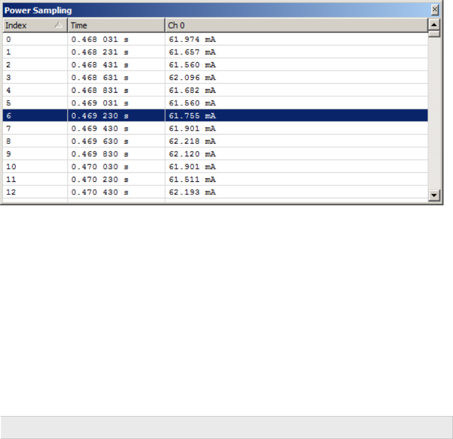
145 CHAPTER 4 Power Sampling Window
4.16 Power Sampling Window
Ozone’s Power Sampling Window employs SEGGER’s Power Trace (PTRACE) API to track the
current drawn by the target. The resulting sampling data is displayed in a tabular fashion.
4.16.1 Hardware Requirements
The Power Sampling Window requires the target to be powered by J-Link/J-Trace, i.e. over
the debug interface. It is to a high degree target-dependent if power supply via the tar-
get interface is supported. Please contact SEGGER if unsure about the capabilities of your
device.
In case your target does not support power via J-Link/J-Trace, you may still want to check
out Ozone’s power profiling capabilities using SEGGER’s Cortex-M trace reference board.
4.16.2 Setup
Power output of the debug probe to the target is switched off per default. Therefore, Ozone
must be instructed to activate power output to the target before a target connection is
established. To do this, system variable VAR_TARGET_POWER_ON is provided. The expected
way to enable power output to the target is to add the statement
Edit.SysVar(VAR_TARGET_POWER_ON,1);
to project script function OnProjectLoad (see Event Handler Functions on page 221).
Power sampling also requires that a positive sampling rate is configured, see below.
4.16.3 Sampling Frequency
The power sampling frequency can be adjusted via the context menu or via command Ed-
it.SysVar using argument VAR_POWER_SAMPLING_SPEED. A sampling frequency of 0 disables
power sampling.
The sampling frequency can be assigned persistently to the project by placing its command
into project script function OnProjectLoad.
The sampling frequency can also be changed via the drop-down field in the toolbar. If the
toolbar is not shown it can be made visibile via the context menu.
Power sampling starts automatically each time the program is resumed and stops auto-
matically each time the program halts.
Ozone User Guide & Reference Manual (UM08025) © 2013-2024 SEGGER Microcontroller GmbH

146 CHAPTER 4 Power Sampling Window
4.16.4 Data Limit
User preference PREF_MAX_POWER_SAMPLES sets the data limit of the power sampling win-
dow. The default data limit is 10M samples. When the data limit is reached, data acquisition
will continue but the oldest samples will be overwritten.
4.16.5 Timeline
Power sampling data, together with symbol and instruction trace data, is visualized in a
combined signal plot (see Timeline Window on page 164). This enables users to establish
a link between target power consumption and program execution. To further support this
correspondence, the selected table row of the Power Sampling Window is synchronized with
the sample cursor of the Timeline Window.
4.16.6 Context Menu
The context menu of the Power Sampling Window provides
the following actions:
Sampling Frequency
Selects the power sampling frequency.
Goto Time
Opens an input dialog that enables users to scroll to a par-
ticular table row.
Export
Opens a file dialog that enables users to export the sampling data to a CSV file. This action
can also be executed from the project script using command Export.PowerGraphs.
Reset Data
Resets the session’s sampling data. This action can also be executed from the project script
using command Timeline.Reset (see Timeline.Reset on page 355).
Toolbar
Toggles the toolbar.
4.16.7 Power Sampling Window Preferences
Section Power Sampling Window Settings on page 87 lists all user preference settings
pertaining to the Power Sampling Window.
Ozone User Guide & Reference Manual (UM08025) © 2013-2024 SEGGER Microcontroller GmbH

147 CHAPTER 4 Registers Window
4.17 Registers Window
Ozone’s Registers Window displays the state of the target’s core, system and peripheral
registers.
Registers window displaying Cortex-M peripherals.
4.17.1 SVD Files
The Registers Window relies on System View Description files (*.svd) that describe the
register set of the target. The SVD standard is widely adopted − many MCU vendors provide
SVD register set description files for their models.
Architecture-specific SVD-Files
Ozone ships with an SVD file for each supported target architecture. These files provide
descriptions of all architecture-defined CPU, system and peripheral registers. Users select
the SVD file that matches their target on the first page of the Project Wizard (see Project
Wizard on page 34).
Vendor-specific SVD-Files
The project wizard also enables users to select an additional vendor-specific SVD file which
describes the vendor-specific peripheral register set of the target. Note that Ozone does
not ship with vendor-specific SVD files out of the box; users have to obtain the file from
their MCU vendor.
Assigning SVD files to the Project
The SVD file selection can be assigned to a project by making corresponding calls to com-
mand Project.AddSvdFile from project script function OnProjectLoad. These calls are added
automatically to Project Wizard generated projects.
Ozone User Guide & Reference Manual (UM08025) © 2013-2024 SEGGER Microcontroller GmbH

148 CHAPTER 4 Registers Window
4.17.2 Register Groups
The Registers Window partitions target registers into the following groups:
Core Registers (Now)
CPU registers that are in use given the current operating mode of the target.
Core Registers (All)
All CPU registers, i.e. the combination of all operating mode registers.
FP Registers
Floating-point registers. This category is only available when the target includes a floating
point unit.
System Registers (e.g. CP-15)
Architecture-defined registers that monitor and control system functions, such as coproces-
sor-15 registers on Cortex-A/R. As a defining criteria, these registers are mapped to ma-
chine instructions and not to memory. System registers can be accessed using commands
Target.SetReg (see Target.SetReg on page 349) and Target.GetReg (see Target.GetReg
on page 349).
Peripheral Registers (CPU)
Architecture-defined special function registers. As a defining criteria, these registers are
memory-mapped. This group is shown below the CPU node.
Peripheral Registers
Implementation (or vendor)-defined special function registers. As a defining criteria, these
registers are memory-mapped. This group is only shown when a vendor-specific register
set description file was specified (see SVD Files on page 147).
Peripheral registers can be accessed using commands:
• Target.ReadU32 (see Target.ReadU32 on page 350)
• Target.WriteU32 (see Target.WriteU32 on page 350)
• Target.GetReg (see Target.GetReg on page 349)
• Target.SetReg (see Target.SetReg on page 349)
4.17.3 Bit Fields
A register that does not contain a single value but rather one or multiple bit fields can
be expanded or collapsed within the Registers Window so that its bit fields are shown
or hidden. Bit fields can be edited just like normal register values.
Flag Strings
A bit field register that contains only bit fields of length 1 (flags) displays the state of it’s
flags as a symbol string. These symbol strings are composed in the following way: the first
letter of a flag’s name is displayed uppercase when the flag is set and lowercase when it
is not set.
Editable Registers and Bit-Fields
Both registers and bit fields that are not marked as read-only within the loaded SVD file
can be edited.
Ozone User Guide & Reference Manual (UM08025) © 2013-2024 SEGGER Microcontroller GmbH

149 CHAPTER 4 Registers Window
4.17.4 Processor Operating Mode
An ARM processor’s current operating mode is displayed as the value of the current CPU
registers group (compare with the title figure). An ARM processor can be in any of 7 op-
erating modes:
USR SVC ABT IRQ FIQ SYS UND
User Supervisor Abort Interrupt Fast IRQ System Undefined
ARM processor operating modes
4.17.5 Register Display
Accessible from the context menu, the Register Display dialog enables users to specify
which registers and register groups are shown by the Registers Window and which ones
are hidden from display.
4.17.6 Context Menu
The Registers Windows’s context menu provides the following actions:
Show Source
Displays the source code line affiliated with the register value (interpreted as instruction
address).
Show Disassembly
Displays the disassembly at the register value.
Show Data
Displays the memory at the register value (interpreted as a memory address).
Display (All) As
Sets the display format of the selected item or the whole window.
Ozone User Guide & Reference Manual (UM08025) © 2013-2024 SEGGER Microcontroller GmbH
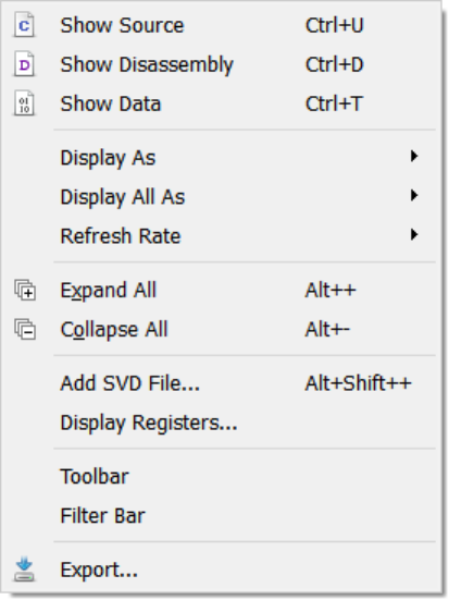
150 CHAPTER 4 Registers Window
Refresh Rate
Selects the refresh rate which is used to sample all peripheral registers that are selected
for periodic update.
The refresh rate can also be specified via the drop-down-box in the toolbar. If the toolbar
is not shown it may be enabled via the context menu.
Expand / Collapse All
Expands or collapses all top-level nodes.
Add SVD File
Opens a file dialog which enables users to add
an extra SVD file to the debug session. The
change is not persistent and will be lost when
the project is closed.
Display Registers
Displays the Register Display dialog that en-
ables users to define which registers are visi-
ble.
Toolbar / Filter bar
Toggles display of the toolbar or filter bar, re-
spectively.
Export
Opens a file dialog that enables users to export
the table content to a CSV file. This action can
also be executed from the project script using command Window.Export.
4.17.7 Table Window
The Registers Window shares multiple features with other table-based debug information
windows provided by Ozone (see Table Windows on page 57).
4.17.8 Multiple Instances
Users may add as many Registers Windows to the Main Window as desired.
Ozone User Guide & Reference Manual (UM08025) © 2013-2024 SEGGER Microcontroller GmbH

151 CHAPTER 4 RTOS Window
4.18 RTOS Window
Ozone’s RTOS Window displays RTOS-specific application information and enables users
to set the execution context of any RTOS task as the current context displayed by the
debugger.
RTOS Window displaying a task list.
4.18.1 RTOS Plugin
The RTOS Window’s application logic is provided by a JavaScript plugin. By implementing
a new plugin following the rules laid out in section RTOS Awareness Plugin on page 231,
support for a specific embedded operating system can be added to the RTOS Window.
Command Project.SetOSPlugin on page 335 loads an RTOS plugin. When this command is
placed into project script function OnProjectLoad, the plugin will be loaded each time the
project is opened. Refer to Project File Example on page 179 for further information.
Ozone ships with RTOS-awareness plugins for embOS, FreeRTOS, ChibiOS, NuttX and
Zephyr.
4.18.2 RTOS Informational Views
RTOS window showing multiple RTOS informational views.
Ozone User Guide & Reference Manual (UM08025) © 2013-2024 SEGGER Microcontroller GmbH

152 CHAPTER 4 RTOS Window
Users − or rather RTOS plugin code − may add multiple tables to the RTOS Window, allowing
the display of multiple types of RTOS information and resources. For example, a task list
may be shown in one table and a semaphore list in another. Section RTOS Awareness Plugin
on page 231 describes the programming possibilities of the RTOS Window in detail.
RTOS informational views are laid out vertically within the RTOS Window’s display area and
can be resized freely.
4.18.3 Task Context Activation
By activating a table row of the task list, the register set of the corresponding task is made
the active execution context of the debugger. What this means is that:
• the Registers Window will show the values of the core registers at the time the task
was interrupted or suspended.
• the Call Stack Window will show the function calling hierarchy at the execution point
of the task.
• the Local Data Window will show the local variables and parameters at the execution
point of the task.
Identifying the Active Task
The active task can be identified by the arrow icon displayed at the left side of its table row.
4.18.4 Context Menu
Refresh
Refreshes all RTOS informational views currently visible.
Reload Plugin
Reloads the JavaScript RTOS plugin. This action must be triggered
in order for changes to the script file to take effect.
Edit Script
Opens the JavaScript RTOS plugin within the Source Viewer, where
it can be edited.
Views
The context menu of the RTOS Window shows an entry for each
RTOS informational view. By toggling an item, the affiliated view is
shown or hidden.
Ozone User Guide & Reference Manual (UM08025) © 2013-2024 SEGGER Microcontroller GmbH

153 CHAPTER 4 Source Files Window
4.19 Source Files Window
Ozone’s Source Files Window lists the source files that were used to generate the debuggee.
4.19.1 Source File Information
The Source Files Window displays the following information about source files:
File
Filename. An icon preceding the filename indicates the file status.
Status
Indicates how the compiler used the source file to generate the debuggee. A source file
that contains program code is displayed as a “compiled” file. A source file that was used to
extract type definitions is displayed as an “included” file.
Size
Byte size of the program machine code encompassed by the source file.
#Insts
The number of instructions encompassed by the source file.
Note
Instruction-level information may not be accessible to Ozone before debug session
startup completion (see Startup Completion Point on page 186). Ozone will display
a warning sign next to table values which may be unavailable due to this reason.
Path
File system path of the source file.
4.19.2 Unresolved Source Files
A source file that the debugger could not locate on the file system is indicated
Ozone User Guide & Reference Manual (UM08025) © 2013-2024 SEGGER Microcontroller GmbH

154 CHAPTER 4 Source Files Window
by a warning sign within the Source Files Window. Ozone supplies users with multiple
options to locate missing source files (see Locating Missing Source Files on page 203).
The user may also edit and correct file paths directly within the Source Files Window.
4.19.3 Context Menu
The context menu of the Source Files Window
adapts to the selected file.
Show Source
Opens the selected file in the Source Viewer
(see Source Viewer on page 155). The same
can be achieved by double-clicking on the file.
Locate File
Opens a file dialog that lets users locate the
selected file on the file system. This context menu is displayed when the selected source
file is missing.
Select In File Explorer
Selects the file within the default file explorer of the operating system.
Filter Bar / Total Value Bar
Toggles the named table header bar.
Export
Opens a file dialog that enables users to export the table content to a CSV file. This action
can also be executed from the project script using command Window.Export.
4.19.4 Table Window
The Source Files Window shares multiple features with other table-based debug information
windows (see Table Windows on page 57).
Ozone User Guide & Reference Manual (UM08025) © 2013-2024 SEGGER Microcontroller GmbH

155 CHAPTER 4 Source Viewer
4.20 Source Viewer
The Source Code Viewer (or Source Viewer for short) enables users to observe program
execution on the source-code level, set source breakpoints and perform quick adjustment
of the program code. Individual source code lines can be expanded to reveal the affiliated
assembly code instructions.
4.20.1 Supported File Types
The Source Viewer is able to display text documents of any file extension. Syntax high-
lighting is limited to the following file types:
• C source code files: *.c, *.cpp, *.h, *.hpp, *.cc
• Assembly code files: *.s, *.asm, *.arm
4.20.2 Execution Counters
Within a switchable sidebar on the left, the Source Viewer may display the execution counts
of individual source lines and instructions (see Code Execution Counters on page 54).
4.20.3 Opening and Closing Documents
Documents can be opened via the file dialog (see File Menu on page 44) or using commands
File.Open and File.Close (see File Actions on page 284).
4.20.4 Editing Documents
Ozone’s Source Viewer provides all standard text editing capabilities and keyboard short-
cuts. Please refer to section Key Bindings on page 130 for an overview of the key bindings
available for editing documents. It is advised to recompile the program following source
code modifications as source-level debug information may otherwise be impaired.
4.20.5 Document Tab Bar
Ozone User Guide & Reference Manual (UM08025) © 2013-2024 SEGGER Microcontroller GmbH

156 CHAPTER 4 Source Viewer
The document tab bar hosts a tab for each source code document that has been opened
in the Source Viewer. The tab of the visible (or active) document is highlighted. Users can
switch the active document by clicking on its tab or by selecting it from the tab bar’s drop-
down button. The drop-down button is located on the right side of the tab bar.
4.20.5.1 Tab Bar Context Menu
The tab bar’s context menu hosts actions that can be used to close documents, to select
the active document within the operating system’s file explorer, and to reload the active
document from disk.
4.20.5.2 Tab Selection Widget
Shortcut Ctrl+Tab brings up the Source Viewer’s
document tab selection widget. This widget fa-
cilitates the activation of document tabs. While
the tab selection widget is visible, hotkeys Ctrl
+Tab and Ctrl+Shift+Tab can be pressed to se-
lect the next or previous document tab, respec-
tively. When the control key is released, the se-
lected document is activated.
4.20.6 Document Header Bar
The document header bar provides users with the ability to quickly navigate to a particular
function within the active document. The header bar hosts two drop-down lists. The drop-
down list on the left side contains all function scopes (namespaces or classes) present
within the active document. The drop-down list on the right side lists all functions that are
contained within the selected scope. When a function is selected, the corresponding source
line is highlighted and scrolled into view.
4.20.7 Symbol Tooltips
By hovering the mouse cursor over a variable, the variable’s value is displayed in a tooltip.
Please note that this feature only works for local variables when the function that contains
the local variable is the active function of the Local Data Window. A function can be activated
by selecting it within the Call Stack Window.
4.20.8 Expression Tooltips
When text is selected within the Source Viewer, it is evaluated as an expression and the
result is displayed in a tooltip (see Working With Expressions on page 201).
Ozone User Guide & Reference Manual (UM08025) © 2013-2024 SEGGER Microcontroller GmbH

157 CHAPTER 4 Source Viewer
4.20.9 Expandable Source Lines
Each text line of the active source code document that contains executable code can be
expanded or collapsed to reveal or hide the affiliated machine instructions. Each such text
line is preceded by an expansion indicator that toggles the line’s expansion state. Further-
more, when the PC Line is expanded, the debugger’s stepping behavior will be the same
as if the Disassembly Window was the active code window (see Stepping Expanded Source
Code Lines on page 187).
4.20.10 Key Bindings
The table below provides an overview of the Source Viewer’s special-purpose key bindings.
Hotkey Description
Ctrl+Tab Selects the next document in the list of open documents.
Ctrl+Shift+Tab Selects the previous document in the list of open documents.
Ctrl+Plus Expands the current line.
Ctrl+Minus Collapses the current line.
Alt+Plus Expands all lines within the current document.
Alt+Minus Collapses all lines within the current document.
Alt+Left Shows the previous location in the text cursor history.
Alt+Right Shows the next location in the text cursor history.
Ctrl+Wheel Adjusts the font size.
F3 Finds the next occurrence of the current search string.
Ctrl+F3 Finds the next occurrence of the word under the cursor.
Next to these keyboard shortcuts, the source viewer also supports the standard hotkeys
provided by debug windows (see Standard Shortcuts on page 51) and code windows {see
Text Cursor Navigation Shortcuts on page 55}.
4.20.11 Syntax Highlighting
The Source Viewer applies syntax highlighting to source code. The syntax highlighting colors
can be adjusted via command Edit.Color (see Edit.Color on page 301) or via the User
Preference Dialog (see User Preference Dialog on page 85).
4.20.12 Source Line Numbers
The display of source line numbers can be toggled by executing command Edit.Preference
using parameter PREF_SHOW_LINE_NUMBERS (see Edit.Preference on page 300) or via the
User Preference Dialog (see User Preference Dialog on page 85).
4.20.13 Context Menu
The Source Viewer’s context menu provides the following actions:
Set / Clear / Edit Breakpoint
Sets, clears or edits a breakpoint on the selected
source code line.
Break On Change
Sets a data breakpoint on the variable under the
cursor. The breakpoint is triggered when the vari-
able’s value changes.
Ozone User Guide & Reference Manual (UM08025) © 2013-2024 SEGGER Microcontroller GmbH
158 CHAPTER 4 Source Viewer
Set Tracepoint (Start/Stop)
Sets a tracepoint on the selected source code line (see Tracepoints on page 208).
Set Next Statement
Sets the PC to the first machine instruction of the selected source code line. Any code
between the current PC and the selected instruction will be skipped, i.e. will not be executed.
Run To Cursor
Advances program execution to the current cursor position. All code between the current
PC and the cursor position is executed.
Show Value in Source
Displays the source code declaration location of the symbol pointed to within the Source
Viewer. Only shown for pointer-type variables.
Show Value in Disassembly
Displays the disassembly location of the symbol pointed to within the Disassembly Window.
Only shown for pointer-type variables.
Show Value in Data
Displays the memory location of the symbol pointed to within the Memory Window. Only
shown for pointer-type variables.
Show Definition
Jumps to the source code definition location of the symbol under the cursor.
Show Declaration
Jumps to the source code declaration location of the symbol under the cursor.
Show Disassembly
Displays the first machine instruction of the selected source code line in the Disassembly
Window (see Disassembly Window on page 117).
Show Data
Displays the data location of the symbol under the cursor within the Memory Window (see
Memory Window on page 135).
Show Call Graph
Displays the call graph of the function under the cursor within the Call Graph Window (see
Call Graph Window on page 98).
Show in Memory Map
Shows the symbol under the cursor within the Memory Usage Window (see Memory Usage
Window on page 139). Call Graph Window (see Call Graph Window on page 98).
Watch
Adds the expression under the cursor to the Watched Data Window (see Watched Data
Window on page 175).
Quick Watch
Shows the expression under the cursor within the Quick Watch Dialog (see Quick Watch
Dialog on page 93).
Ozone User Guide & Reference Manual (UM08025) © 2013-2024 SEGGER Microcontroller GmbH

159 CHAPTER 4 Source Viewer
Graph
Adds the expression under the cursor to the Data Sampling Window (see Data Sampling
Window on page 113).
Goto PC
Displays the PC line. If the source code document containing the PC line is not open or
visible, it is opened and brought to the front.
Goto Line
Scrolls the active document to the line number obtained from an input dialog.
Find
Opens the Quick Find Widget with the word under the cursor (see Quick Find Widget on
page 91).
Find In Trace
Opens the Find In Trace Dialog with the word under the cursor (see Find In Trace Dialog
on page 71).
Expand / Collapse All
Expands or Collapses all expandable lines within the current document.
Cut/Copy/Paste
Standard text editor actions.
Line Numbers
Displays a submenu that enables users to specify the line numbering frequency.
Execution Counters
Toggles the display of Code Execution Counters (see Code Execution Counters on page 54).
Instruction Encodings
Toggles the display of instruction encodings within inline assembly code.
Pseudo Instructions
Enables or disables pseudo-instruction display.
Export
Opens a file dialog that enables users to export the content of the current source window,
including side bar information, to a CSV file. This action can also be executed from the
project script using command Window.Export.
4.20.14 Font
The Source Viewer’s font can be adjusted by executing command Edit.Font (see Edit.Font
on page 302) or via the User Preference Dialog (see User Preference Dialog on page 85).
Quick Adjustment of the Font Size
The font size can be quick-adjusted by scrolling the
mouse wheel while holding down the control key.
This action will also bring up the font size selection
widget shown to the right. The font size selection
Ozone User Guide & Reference Manual (UM08025) © 2013-2024 SEGGER Microcontroller GmbH
160 CHAPTER 4 Source Viewer
widget provides additional controls that facilitate font resizing. It can be used to save the
selected font size session-persistently and to reset the font size to the last saved value.
4.20.15 Code Window
The Source Viewer shares multiple features with Ozone’s second code window, the Dis-
assembly Window. Refer to Code Windows on page 52 for a shared description of these
windows.
4.20.16 Source Viewer Preferences
Section Source Viewer Settings on page 88 lists all user preference settings pertaining to
the source viewer.
Ozone User Guide & Reference Manual (UM08025) © 2013-2024 SEGGER Microcontroller GmbH

161 CHAPTER 4 Terminal Window
4.21 Terminal Window
Ozone’s Terminal Window provides text transmission of textual information from and to the
debuggee. Text output generated by the debugee is displayed in the terminal window.
Non-printable control characters are either removed or transformed into octal C-string-
sequences. ANSI escape sequences carrying color information are supported.
4.21.1 Supported IO Techniques
The Terminal Window supports three communication techniques for transmission of textual
data from the debugger to the debuggee and vice versa that are described in Terminal IO
on page 197.
4.21.2 Terminal Input
A debuggee may request user input via
the Semihosting or RTT technique. RTT in-
put requests are answered over the terminal
prompt, while Semihosting input requests can
be answered over the terminal prompt or al-
ternatively over a popup dialog.
This common debugging technique enables
users to manipulate the program state at ap-
plication-defined execution points and to ob-
serve the resulting runtime behavior.
4.21.2.1 Terminal Prompt
The Terminal Window’s input text box is used
to respond to user input requests via RTT. or semihosting. The terminal prompt is located
at the bottom of the Terminal Window.
Input Termination
A string-termination character or a line break may be automatically appended to terminal
input before the text is sent to the debuggee. Input termination behavior can be adjusted
via the context menu or via command Edit.Preference (see Edit.Preference on page 300).
Asynchronous Input
Textual data can be send to the debuggee even when there is no pending input request. In
this case, the text will be stored at the next free RTT memory buffer location.
4.21.3 Ansi Escape Sequences
ANSI sequences for coloring text are supported. The following features the ANSI standard
offers, are supported:
• Standard color palette for foreground and background.
• High-intensity basic color palette for foreground and background.
Ozone User Guide & Reference Manual (UM08025) © 2013-2024 SEGGER Microcontroller GmbH

162 CHAPTER 4 Terminal Window
• 8-bit color ID palettes for selecting one of 256 entries from a color palette offering the
standard colors, high-intensity colors, grayscale colors and 216 8-bit colors
• 24-bit RGB-values for true color usage for foreground and background
• Bold formatting leads to high-intensity foreground color when using the standard color
palette.
• Underline formatting leads to high-intensity background color when using the standard
color palette.
An ANSI escape sequence has the format
<esc>“[”<parameter 1>[“;”<parameter 2>[…“;”<parameter n>]]“m”.
The sequence “<esc>[93;48;5;21m” will display subsequent text in bright yellow color on
blue background.
The following table describes the parameter values supported by Ozone:
Parameter Description
30 - 37 Set foreground color in one of the standard colors.
90 - 97 Set foreground color in one of the standard high-intensity colors.
40 - 47 Set background color in one of the standard colors.
100 - 107 Set background color in one of the standard high-intensity colors.
38;5 Set foreground color via Color ID.
48;5 Set background color via Color ID.
38;2 Set foreground color via RGB value.
48;2 Set background color via RGB value.
1
Set foreground to bold mode, which makes the foreground color
bright.
4 Set underline mode, background color set to high-intensity.
24 Reset the underline mode, background set to normal intensity.
0 Reset, set default colors for foreground and background.
Other features the ANSI standard offers are not supported.
4.21.4 Logging
In addition to displaying the data received from the debugee in the terminal window, Ozone
can write the information into a log file. Logging can be enabled and the name of the log
file can be specified by means of the command Project.SetTerminalLogFile.
4.21.5 Control Character Handling
The terminal window’s handling of non-printable control characters can be controlled via the
preference PREF_TERMINAL_NO_CONTROL_CHARS. This allows to either suppress the display
of such control characters or transform it into an octal sequence as found in a C-string.
4.21.6 Terminal Window Limit
The amount of data displayed in the terminal window can be limited. For that purpose there
is the preference PREF_TERMINAL_DATA_LIMIT which specifies the amount of data up to
which the terminal window will accept incoming data. Once that limit is reached, a message
is displayed in the console window and additional incoming data is rejected.
4.21.7 Context Menu
The Terminal Window’s context menu provides the following actions:
Ozone User Guide & Reference Manual (UM08025) © 2013-2024 SEGGER Microcontroller GmbH

163 CHAPTER 4 Terminal Window
Copy
Copies the selected text to the clipboard.
Select All
Selects all text lines.
Clear
Clears the Terminal Window.
Clear On Reset
When checked, the window’s text area is cleared fol-
lowing each program reset.
Capture RTT
Indicates whether the Terminal Window captures text
messages that are output by the debuggee via SEG-
GER’s RTT technique.
Capture SWO
Indicates whether the Terminal Window captures text
messages that are output by the debuggee via the SWO interface.
Zero-Terminate Input
Indicates if a string termination character (\0) is appended to user input before the input
is sent to the debuggee.
Echo Input
When checked, each terminal input is appended to the terminal window’s text area.
End Of Line Input
Specifies the type of line break to be appended to terminal input before the input is send
to the debuggee (see Newline Formats on page 262).
Semihosting Settings
Opens the Semihosting Settings Dialog (see Semihosting Settings Dialog on page 81).
Export
Opens a file dialog that enables users to export the window content to a CSV file. This
action can also be executed from the project script using command Window.Export.
4.21.8 Terminal Window Preferences
Section Terminal Window Settings on page 88 lists all user preference settings pertaining
to the Terminal Window.
Ozone User Guide & Reference Manual (UM08025) © 2013-2024 SEGGER Microcontroller GmbH

164 CHAPTER 4 Timeline Window
4.22 Timeline Window
Ozone’s timeline window visualizes the supported trace and data sampling channels in a
combined signal plot.
4.22.1 Overview
The timeline provides multiple interactive features that allow users to quickly understand
the time course of the displayed data both on a broad and on a narrow time scale.
The timeline is subdivided into 3 data panes:
Position Pane Description
Top Data Displays the graphs of recorded variables and expressions
Middle Power Displays the target’s power consumption
Bottom Code Displays the course of the program’s call stack
The visibility of each pane can be toggled via the toolbar or the context menu.
All data panes share a common time axis, or timescale. This enables users to e.g:
• compare the target’s power consumption against code execution
• observe selected data state at a particular program execution point
Ozone User Guide & Reference Manual (UM08025) © 2013-2024 SEGGER Microcontroller GmbH

165 CHAPTER 4 Timeline Window
In the title figure, the debuggee switched 3 LED’s on and off in short succession. Traced
variable NumLEDs was incremented or decremented each time an LED was switched on or
off. As can be seen, the target’s power consumption is directly proportional to the number
of active LEDs. The code pane shows multiple call stack transitions (shown as spikes).
Zooming into one of the call stack transitions presents the following view:
Timeline plot after zooming in
confirming that each call stack transition corresponds to the toggling of an LED.
Instruction Ticks
The vertical ticks displayed in the figure above mark instruction boundaries. The instruction
ticks help to understand relative instruction execution durations, for example the execution
time difference of a load/store and an ALU instruction.
4.22.2 Navigating the Window with the Mouse
Navigating the window with the mouse is quite intuitive:
• Moving the mouse will move the Hover Cursor.
• A single left mouse click will position the Sample Cursor.
• Dragging the mouse will pan the selected pane vertically and all panes horizontally.
• Spinning the scroll wheel will perform the action specified in the preferences: pan
horizontally, pan vertically, zoom horizontally, zoom vertically, or no action. Horizontal
actions are performed on all panes, vertical actions only on the pane under the mouse
cursor.
• Spinning the scroll wheel while [ctrl] is pressed will zoom the pane under the mouse
cursor horizontally.
• Spinning the scroll wheel while [shift] is pressed will zoom the pane under the mouse
cursor vertically.
• Tilting the scroll wheel (or using the horizontal scroll wheel) will pan horizontally.
4.22.3 Hardware Requirements
The timeline window has individual hardware requirements for each of the 3 data panes:
Pane Hardware Requirements
Data Same as Data Sampling Window on page 113.
Power Same as Power Sampling Window on page 145.
Code Same as Instruction Trace Window on page 128.
In case your target does not satisfy all of the above hardware requirements, you may still
want to check out all capabilities of the Timeline Window using SEGGER’s Cortex-M trace
reference board.
Ozone User Guide & Reference Manual (UM08025) © 2013-2024 SEGGER Microcontroller GmbH
166 CHAPTER 4 Timeline Window
4.22.4 Setup
The timeline window is setup using project settings. Each data pane has an individual
configuration requirement, as explained by this section.
Data
The list of traced expressions is setup using the Data Sampling Window on page 113. The
data sampling rate is configured in any of the ways described in section Sampling Frequency
on page 145. A data sampling rate of 0 disables data trace.
Power
The power sampling rate is configured in any of the ways described in section Sampling
Frequency on page 145. A power sampling rate of 0 disables power trace.
Code
In order to obtain a consistent output when debugging multi-threaded applications, either:
• an RTOS-awareness plugin must have been loaded (see Project.SetOSPlugin on
page 335) or
• information about program code that performs a task switch must have been supplied
(see OS.AddContextSwitchSymbol on page 357).
For applications that include custom instructions, additionally:
• a disassembly support plugin must have been loaded (see Project.SetDisassemblyPlugin
on page 334).
4.22.5 Code Pane
This section describes details of the code pane.
Call Frames
Each horizontal bar of the code pane represents a function invocation, or call frame. The left
and right boundaries of a call frame denote the points in time when the program entered
and exited the called function.
Exception Frames
An exception handler or interrupt service routine frame is painted with rounded corners
and a deeper color saturation level (compare with SysTick_Handler in the figure below).
Frame Tooltips
When the mouse cursor hovers over a call frame of the timeline plot, a tooltip pops up that
informs about frame properties such as the number of encompassed instructions.
Task Context Highlighting
Instruction blocks that were executed by different threads of the target application are
distinguishable through the window background color. The task context highlighting fea-
ture requires an OS-awareness-plugin to have been set (see RTOS Awareness Plugin on
page 231).
Ozone User Guide & Reference Manual (UM08025) © 2013-2024 SEGGER Microcontroller GmbH

167 CHAPTER 4 Timeline Window
Task context highlighting within the Timeline Window.
4.22.6 Sample Cursor
The sample cursor marks the program execution point that is currently set within the PC
aware debug information windows. This enables users to get a complete view of the program
execution context for any position of the timeline plot. Conversely, changing the selection
within one of the PC-aware debug windows also causes the sample cursor to adjust.
The default color used for execution point highlighting is yellow and can be adjusted via
command Edit.Color (see Edit.Color on page 301) or via the User Preference Dialog (see
User Preference Dialog on page 85).
The sample cursor is synchronized with Ozone’s execution point aware debug windows.
Ozone User Guide & Reference Manual (UM08025) © 2013-2024 SEGGER Microcontroller GmbH

168 CHAPTER 4 Timeline Window
4.22.6.1 Positioning the Sample Cursor
The sample cursor can be positioned by single click, drag & drop or the keys shown in the
table below. In this table, “sample” refers to the data sample or instruction of the pane
which has the input focus.
Key Description
Left/Right Moves the sample cursor 1/5 grid spacing left or right
Shift + Left/Right Moves the sample cursor 1 grid spacing left or right
Up/Dn Moves the sample cursor to the previous/next sample
Page Up Moves the sample cursor 1 page left
Page Down Moves the sample cursor 1 page right
Home Moves the sample cursor to the least recent sample
End Moves the sample cursor to the most recent sample
4.22.6.2 Pinning the Sample Cursor
The sample cursor can be pinned to a fixed window position via context menu entry “Cur-
sor”. When pinned to the window, the sample cursor will always stay visible regardless of
any view modification.
4.22.7 Hover Cursor
The hover cursor is a vertical line displayed below the mouse cursor that follows the move-
ments of the mouse. At the intersection point of the hover cursor with each graph, a value
box is displayed that indicates the graph’s signal value at that position. The figure below
and the title figure give examples for the hover cursor.
4.22.8 Time Reference Points
To ease the measurement of time distances, the context menu provides an option to toggle
a time reference at the position of the sample cursor. For each time reference, an additional
label will be displayed next to the hover cursor that shows the time distance between the
hover cursor and the time reference.
4.22.9 Graph Legends
Each data pane provides a graph legend with a context menu:
Ozone User Guide & Reference Manual (UM08025) © 2013-2024 SEGGER Microcontroller GmbH

169 CHAPTER 4 Timeline Window
The graph legend enables users to:
• show or hide individual graphs
• assign colors to graphs
• assign a vertical scale factor to graphs
A graph legend can be freely moved within a pane.
4.22.10 Toolbar
The toolbar of the timeline window has the following layout, from left to right:
• 3 buttons to toggle the display of the 3 data panes.
• a drop-down box which sets the debug event upon which timeline data is cleared (see
Clear Event on page 172).
• a drop-down box sets the time resolution of the timeline to discrete levels.
• a slider which sets the time resolution of the timeline to continuous levels.
The time resolution drop-down provides two special options:
• continuous: the time resolution is selected via the zoom slider.
• data fit: the time resolution adapts to the data in order to fit all data into view.
If the toolbar is not shown it can be made visible via the context menu.
4.22.11 Context Menu
The panes of the timeline window provide individual context menus. The illustration below
depicts the context menu of the code and power panes. The context menu of the data pane
is identical to that of the power pane, with the exception of entries Show Average, Show
Time Average and Show Names at Cursor.
Ozone User Guide & Reference Manual (UM08025) © 2013-2024 SEGGER Microcontroller GmbH

170 CHAPTER 4 Timeline Window
Context menus of the code pane (left) and power pane (right).
Common Actions
Context menu actions provided by all panes:
Action Description
Fit Width
Fits the selected data horizontally into view. When there is no se-
lection, fits all data of the focused pane into view
Fit Height
Fits the selected data vertically into view. When there is no selec-
tion, fits all visible data of the focused pane into view
Go To Cursor Scrolls the sample cursor into view
Go To Reference Scrolls to the time reference nearest to the sample cursor
Go To Time Shows an input dialog and scrolls to input plot position
Cursor Pins the sample cursor at a fixed window position
Time Scale Sets the time resolution of the timeline plot
Toggle Reference Sets or clears a time reference at the sample cursor position
Clear All References Removes all time references
Ozone User Guide & Reference Manual (UM08025) © 2013-2024 SEGGER Microcontroller GmbH

171 CHAPTER 4 Timeline Window
Action Description
Open Data Window Opens the data sampling window affiliated with the pane
Reset Data
Resets the session’s trace and sampling data and thereby all
timeline panes.
Auto Fit Height
When checked, the zoom factor of the y-axis auto-adjusts to data
in order to provide integer-valued grid labels. When unchecked,
the zoom factor of the y-axis remains unchanged.
Data Toggles the data pane
Power Toggles the power pane
Code Toggles the code pane
Legend Toggles the pane’s graph legend
Toolbar Toggles the toolbar
Sampling Pane Actions
Context menu actions provided by the data and power panes:
Action Description
Sampling Frequency
Sets the data sampling frequency. Entry “Off” (0) disables data
sampling.
Set Offset To Code
Starts operation Set Offset To Code (see Set Offset To Code on
page 173)
Draw Points Displays sampling data as a point cloud instead of graphs
Uniform Sample
Spacing
When checked, sample timestamps are computed by Ozone
based on the sampling frequency. When unchecked, Ozone uses
the sample timestamps provided by J-Link.
Data Pane Actions
Context menu actions exclusive to the data pane:
Action Description
Show Names at Cur-
sor
When checked, displays the
expression or variable name
together with the value in the
boxes close to the hover cur-
sor.
Power Pane Actions
Context menu actions exclusive to the power pane:
Action Description
Show Average
Selects the sample width of the running-average filter used to
compute the filtered power graph. The filtered power graph is
Ozone User Guide & Reference Manual (UM08025) © 2013-2024 SEGGER Microcontroller GmbH

172 CHAPTER 4 Timeline Window
Action Description
displayed along with to the power graph within the power pane.
A sample width of 0 disables the display of the filtered power
graph.
Show Time Average
Selects the time range used to compute the average power val-
ue. The average power value is displayed within the data legend
of the power pane. It is taken at the position of the hover cur-
sor or the most recent data sample, when the hover cursor is not
visible.
Code Pane Actions
Context menu actions exclusive to the code pane:
Action Description
Set Breakpoint Sets/clears a breakpoint on the function of the selected frame
Go To Start/End of Sets the sample cursor on to the start/end of the selected frame
Go To Next/Previous
execution of
Sets the sample cursor on to the next/previous execution of the
selected frame
Go To Next/Previous
function on level
Sets the sample cursor on to the next/previous function on the
selected stack level
Time Stamps Selects the time unit to use with frame tooltips.
4.22.12 Settings
The timeline window evaluates the following system variables settings:
System Variable Description
VAR_TRACE_MAX_INST_CNT
Maximum number of instructions that can be ac-
quired from target and displayed within the code
pane
VAR_TRACE_CORE_CLOCK
Conversion factor used to convert execution times
between CPU cycles and time units
Section Timeline Window Settings on page 89 lists all user preference settings pertaining
to the Timeline Window.
4.22.13 Clear Event
The debug event upon which the session’s trace and sampling data is cleared can be
specified via the toolbar, the context menu or command Edit.Preference. The possible val-
ues of user preference PREF_TIMELINE_CLEAR_EVENT are listed in section Clear Events on
page 264. The clear event takes effect even when the timeline window is not open. In
addition, timeline data can also be cleared from the project script using command Time-
line.Reset (see Timeline.Reset on page 355).
Note
When the timeline is cleared, the data contents of the Instruction Trace Window, Code
Profile Window, Data Sampling Window and Power Sampling Window are reset as well.
Ozone User Guide & Reference Manual (UM08025) © 2013-2024 SEGGER Microcontroller GmbH

173 CHAPTER 4 Timeline Window
4.22.14 Set Offset To Code
This feature allows specifying an offset on the time axis to the data and power panes
with respect to the code pane. The intention is to change the alignment or fix a potential
misalignment in the display of the repsective curves.
Assume the following state: An application toggles a variable and sets an LED according
to the new state of the variable. In the data pane we can see the graph going from 0 to 1
and the power graph also indicates an increase in power consumption caused by the LED
now being active. The code that triggers that action is executed shortly beforehand at the
cursor position. This can be seen in the subsequent graphic:
Adding an offset to the data graph’s position on the time axis allows aligning the rising edge
with the code that changes the variable and toggles the LED.
To do so, first set the cursor onto the rising edge in the power pane by clicking onto that
rising edge. Once the cursor is in place, open the context menu of the data pane and select
“Set Offset to Code”. A 2nd cursor, the offset cursor, will appear and the area between the
two cursors will be highlighted. In addition, below the code pane, a text is displayed which
shows the available options.
Move the offset cursor to the respective place in the code pane.
Ozone User Guide & Reference Manual (UM08025) © 2013-2024 SEGGER Microcontroller GmbH

174 CHAPTER 4 Timeline Window
Once the offset cursor is in the correct place, press the [Enter] key. Now the offset will be
applied to the data pane and the rising edge will be aligned with the respective code. Please
note that the offset is applied only to the data graph since the context menu was opened
for the data pane. In order to specify an offset for the power graph please follow the same
steps but open the context menu for the power pane.
In order to abort the action, please press the [Esc] key.
For removing the offset from a pane, open the pane’s context menu, select “Set Offset to
Code” and press the [Del] key.
Panning and zooming may be used for setting both the cursor and the offset cursor in order
to precisely hit the correct spot in the respective pane.
Ozone User Guide & Reference Manual (UM08025) © 2013-2024 SEGGER Microcontroller GmbH

175 CHAPTER 4 Watched Data Window
4.23 Watched Data Window
Ozone’s Watched Data Window tracks the values of C-style expressions that the user chose
for explicit observation (see Working With Expressions on page 201).
4.23.1 Adding Expressions
An expression can be watched, i.e. added to the Watched Data Window, in any of the
following ways:
• via context menu entry Watch of any symbol window.
• via command Window.Add (see Window.Add on page 308).
• via context menu entry “Watch…” that opens an input dialog.
• by entering an expression into the last table row, which acts as an input field.
• by dragging a symbol or any other source of text mime data onto the window.
The list of expressions can be reordered in any of the following ways:
• By dragging an expression to a new position
• By using the “up” and “down” buttons of the toolbar. If the toolbar is not shown it can
be made visible via the context menu.
• By using hotkeys “Ctrl+Up” and “Ctrl+Dn”
4.23.2 Local Variables
The Watched Data Window supports expressions that contain local variables. An expression
containing a local variable that is out of scope, i.e. whose parent function is not the current
function, displays the location text “out of scope”.
4.23.3 Live Watches
The Watched Data Window supports live updating of expressions while the program is
running. Each expression can be assigned an individual update frequency via the windows
context menu or via command Edit.RefreshRate (see Edit.RefreshRate on page 303).
Note
Ozone User Guide & Reference Manual (UM08025) © 2013-2024 SEGGER Microcontroller GmbH

176 CHAPTER 4 Watched Data Window
The live watches feature requires the target to support background memory access
or the connected J-Link/J-Trace debug probe to support BMA emulation.
Ozone system variable VAR_ALLOW_BMA_EMULATION controls if BMA emulation is to auto-
matically take effect when hardware support is not present.
4.23.4 Quick Watches
Where it suffices to evaluate a symbol expression momentarily, users can resort to the
Quick Watch Dialog.
4.23.5 Context Menu
The Watched Data Window’s context menu
provides the following actions:
Remove
Removes an expression from the window.
Set/Clear/Edit Data Breakpoint
Sets/clears/edits a data breakpoint on the
selected expression (see Data Breakpoints
on page 191).
Graph
Adds the selected expression to the Data
Sampling Window.
Show Value in Source
Displays the source code declaration lo-
cation of the symbol pointed to within
the Source Viewer. Only shown for point-
er-type variables.
Show Value in Disassembly
Displays the disassembly location of the
symbol pointed to within the Disassembly
Window. Only shown for pointer-type vari-
ables.
Show Value in Data
Displays the memory location of the sym-
bol pointed to within the Memory Window.
Only shown for pointer-type variables.
Show Source
Displays the source code declaration location of the selected variable in the Source Viewer
(see Source Viewer on page 155).
Show Data
Displays the data location of the selected variable in either the Memory Window (see Mem-
ory Window on page 135) or the Registers Window (see Registers Window on page 147).
Ozone User Guide & Reference Manual (UM08025) © 2013-2024 SEGGER Microcontroller GmbH
177 CHAPTER 4 Watched Data Window
Display (All) As
Changes the display format of the selected item or of all items (see Display Format on
page 57).
Refresh Rate
Sets the refresh rate of the selected expression (see Live Watches on page 175).
Add
Opens the Watch Dialog (see Working With Expressions on page 201).
Remove All
Removes all items from the Watched Data Window.
Expand/Collapse All
Expands or collapses all top-level nodes.
Member Functions
Toggles the display of class member functions. This item is only visible when the debuggee’s
source language is C++.
Tool Bar
Toggles display of the tool bar.
Filter Bar / Total Value Bar
Toggles the named table header bar.
Export
Opens a file dialog that enables users to export the table content to a CSV file. This action
can also be executed from the project script using command Window.Export.
4.23.6 Multiple Instances
Users may add as many Watched Data Windows to the Main Window as desired.
4.23.7 Table Window
The Watched Data Window shares multiple features with other table-based debug informa-
tion windows provided by Ozone (see Table Windows on page 57).
Ozone User Guide & Reference Manual (UM08025) © 2013-2024 SEGGER Microcontroller GmbH

Chapter 5
Debugging With Ozone
This chapter explains how to debug an embedded application using Ozone’s basic and ad-
vanced debug features.
Ozone User Guide & Reference Manual (UM08025) © 2013-2024 SEGGER Microcontroller GmbH
179 CHAPTER 5 Project Files
5.1 Project Files
An Ozone project file (.jdebug) stores settings that configure the debugger so that it is ready
to debug a program on a particular hardware setup (microcontroller and debug interface).
When a project file is opened or created, the debugger is initialized with the project settings.
5.1.1 Project File Example
Illustrated below is an example project file that was created with the Project Wizard (see
Project Wizard on page 34). As can be seen, project settings are specified in a C-like syntax
and are placed inside a function. This is due to the fact that Ozone project files are in fact
programmable script files.
/*********************************************************************
*
* OnProjectLoad
*
* Function description
* Executed when the project file is opened. Required.
*
**********************************************************************
*/
void OnProjectLoad (void) {
Project.SetDevice ("STM32F103ZE");
Project.SetHostIF ("USB", "0");
Project.SetTargetIF ("SWD");
Project.SetTIFSpeed ("2 MHz");
File.Open ("C:/Examples/Blinky_STM32F103_Keil/Blinky/RAM/Blinky.axf");
}
5.1.2 Opening Project Files
A project file can be opened in any of the following ways:
• Main Menu (File → Open)
• Recent Projects List (File → Recent Projects)
• Hotkey Ctrl+O
• User action File.Open (see File.Open on page 293)
5.1.3 Creating Project Files
A project file can be created manually using a text editor or with the aid of Ozone’s Project
Wizard (see Project Wizard on page 34). The Project Wizard creates minimal project files
that specify only the required settings.
5.1.4 Programmability
Users may reprogram key debug operations within the project file. This aspect of project
files is covered in detail in section Project Script on page 220.
5.1.5 Project Settings
Any user action that configures the debugger in some way is a valid project setting (see
User Actions on page 42). Project settings are specified by inserting user action commands
into the obligatory script function OnProjectLoad (compare with Project File Example on
page 179). The most relevant project settings include:
• Program File
• Target Device
• Connection Settings
• RTOS Plugin
Ozone User Guide & Reference Manual (UM08025) © 2013-2024 SEGGER Microcontroller GmbH

180 CHAPTER 5 Project Files
• Source File Resolution Settings
each of these settings are described in more detail below.
5.1.5.1 Program File
The program to be debugged is specified using command File.Open. This command has a
single file path argument which can be an absolute path or a path relative to the project
file directory (see File.Open on page 293). Section Supported Program File Types on
page 181 lists the supported program file types.
5.1.5.2 Target Device
Command Project.SetDevice specifies the target device (see Project.SetDevice on
page 331).
5.1.5.3 Connection Settings
Commands Project.SetHostIF and Project.SetTargetIF specify in which way the debug probe
is connected to the Host-PC and to the target device, respectively (see Project Actions on
page 286).
5.1.5.4 RTOS Plugin
Command Project.SetOSPlugin specifies the file path or name of the plugin that adds RTOS
awareness to the debugger (see Project.SetOSPlugin on page 335). Ozone currently ships
with three RTOS awareness plugins - SEGGER embOS, FreeRTOS, ChibiOS, NuttX and
Zephyr. A guide on programming RTOS plugins is given by section RTOS Awareness Plugin
on page 231.
5.1.5.5 Source File Resolution Settings
Settings that allow Ozone to find source files that have been moved to a new location after
the program file was build are described in File Path Resolution Sequence on page 203.
5.1.5.6 Required Project Settings
A valid project file must specify the following settings:
Setting Description
Project.SetDevice The name of the target device.
Project.SetHostIF
Specifies how the J-Link/J-Trace debug probe is connected to
the Host-PC.
Project.SetTargetIF
Specifies how the J-Link/J-Trace debug probe is connected to
the target.
Project.SetTifSpeed Specifies the data transmission speed.
5.1.6 Project Load Diagnostics
Each time a project file is opened, Ozone performs an integrity check of the project file
and its settings. When issues are detected, the Project Load Diagnostics Dialog on page 77
is shown.
5.1.7 User Files
When a project is closed, Ozone associates a user file (*.user) with the project and stores it
next to the project file. The user file contains window layout information and other appear-
ance settings in an editable format. The next time the project is opened, Ozone restores
the user interface layout from the user file. User files may be shared along with project
files in order to migrate the project-individual look and feel.
Ozone User Guide & Reference Manual (UM08025) © 2013-2024 SEGGER Microcontroller GmbH
181 CHAPTER 5 Program Files
5.2 Program Files
The program to be debugged is specified as part of the project settings or is opened man-
ually from the user interface.
5.2.1 Supported Program File Types
Ozone supports the following program file types:
• ELF or compatible files (*.elf, *.out, *.axf)
• Motorola s-record files (*.srec, *.mot)
• Intel hex files (*.hex)
• Binary data files (*.bin)
5.2.2 Symbol Information
Only ELF or compatible program files contain symbol information. When specifying a pro-
gram or data file of different type, source-level debug features will be unavailable. In ad-
dition, all debugger functionality requiring symbol information − such as the variable or
function windows − will be unavailable.
Debugging without Symbol Information
Ozone provides many facilities that allow insight into programs that do not contain symbol
information. With the aid of the Disassembly Window, program execution can be observed
and controlled on a machine code level. The target’s memory and register state can be ob-
served and modified via the Memory and Registers Windows. Furthermore, many advanced
debug features such as instruction trace and terminal IO are operational even when the
program file does not provide symbol information.
Configuring the ELF Parser
Ozone provides command Elf.SetConfig to configure the ELF parser for optimal handling of
special situations and corner cases. This command usually does not need to be employed.
5.2.3 Opening Program Files
When the program file is not specified as part of the project settings (using action
File.Open), it needs to be opened manually. A program file can be opened via the Main
Menu (File → Open), or by entering command File.Open into the Console Window’s com-
mand prompt (see File.Open on page 293).
Effects of opening a Program File
When an ELF- or compatible program file is opened, the program’s main function is dis-
played within the Source Viewer. Furthermore, all debug information windows that dis-
play static program entities are initialized. Specifically, these are the Functions Window
(see Functions Window on page 123), Source Files Window (see Source Files Window on
page 153), Global Data Window (see Global Data Window on page 126) and Code Profile
Window (see Code Profile Window on page 105).
5.2.4 Data Encoding
When an ELF or compatible program file is opened, Ozone senses the program file’s data
encoding (data endianness) and configures itself for that encoding. Additionally, the endi-
anness mode of the attached target is set to the program file’s data encoding if supported
by the target. The target’s endianness mode can also be specified independently via the
J-Link Settings Dialog (see J-Link Settings Dialog on page 76) and action Target.SetEndi-
aness (see Target.SetEndianess on page 353).
Ozone User Guide & Reference Manual (UM08025) © 2013-2024 SEGGER Microcontroller GmbH

182 CHAPTER 5 Starting the Debug Session
5.3 Starting the Debug Session
After a project was opened or created and a program file was specified, the debug session
can be started. The debug session is started via command Debug.Start (see Debug.Start on
page 323). This action can be triggered from the Debug Menu or by pressing the hotkey F5.
When the start-up procedure is complete, the debug information windows that display
target data will be initialized and the code windows will display the program execution point
(PC Line).
5.3.1 Connection Mode
The operations that are performed during the startup sequence depend on the value of
the connection mode parameter (see Debug.SetConnectMode on page 324). The different
connection modes are described below.
5.3.1.1 Download & Reset Program
The default connection mode “Download & Reset Program” performs the following startup
operations:
Startup Phase Description
Phase 1: Connect A connection to the target is established via J-Link/J-Trace.
Phase 2: Breakpoints
Pending (data) breakpoints that were set in offline mode are
applied.
Phase 3: Reset A hardware reset of the target is performed.
Phase 4: Download The debuggee is downloaded to target memory.
Phase 5: Finish
The initial program operation is performed (see Initial Pro-
gram Operation on page 182).
Flow Chart
Section Startup Sequence Flow Chart on page 274 provides a flow chart of the Download &
Reset Program startup sequence. This chart can be used as a reference when reprogram-
ming the sequence via the scripting interface.
5.3.1.2 Attach to Running Program
This connection mode attaches the debugger to the debuggee by performing phases 1 and
2 of the default startup sequence (see Download & Reset Program on page 182).
5.3.1.3 Attach & Halt Program
This connection mode performs the same operations as “Attach To Running Program” and
additionally halts the program.
5.3.1.4 Setting the Connection Mode
The connection mode can be set via command Debug.Set-
ConnectMode (see Debug.SetConnectMode on page 324),
via the System Variable Editor (see System Variable Editor
on page 82) or via the Connection Menu (Debug → Start De-
bugging). The Connection Menu is illustrated on the right.
5.3.2 Initial Program Operation
When the connection mode is set to Download & Reset Program, the debugger finishes the
startup sequence in one of the following ways, depending on the reset mode (see Reset
Mode on page 187):
Ozone User Guide & Reference Manual (UM08025) © 2013-2024 SEGGER Microcontroller GmbH

183 CHAPTER 5 Starting the Debug Session
Reset Mode Initial Program Operation
Reset & Break at Symbol Program execution is advanced to a particular symbol.
Reset & Halt The program is halted at the reset PC.
Reset & Run The program is resumed.
5.3.3 Reprogramming the Startup Sequence
Parts or all of the Download & Reset Program startup sequence can be reprogrammed. The
process is discussed in detail in DebugStart.
Ozone User Guide & Reference Manual (UM08025) © 2013-2024 SEGGER Microcontroller GmbH

184 CHAPTER 5 Register Initialization
5.4 Register Initialization
5.4.1 Overview
Ozone initializes the program counter register (PC) and possibly also the stack pointer
register (SP) in an architecture-specific manner each time…
• a program file was downloaded to target memory.
• a hardware-reset of the target was performed.
In the download case, register initialization takes place after file contents have been written
to target memory and before the initial program operation is performed (see Initial Program
Operation on page 182).
Note
Ozone performs a hardware reset of the target…
• before a program file is downloaded
• when the program is user-reset
5.4.2 Register Reset Values
The standard register initialization values are depicted in the table below. The depicted
values apply for both download and hardware reset.
Architecture Initial PC Initial SP
Legacy ARM 0
Cortex-A/R 0
Cortex-M [0x4] [0x0]
RISC-V 0
An empty table cell indicates that Ozone leaves the register uninitialized. A value in square
brackets means that the value is interpreted as a memory location from which the register
reset value is read.
5.4.3 Manual Register Initialization
Users are able to override Ozone’s default register initialization behavior by implementing
script functions AfterTargetDownload and/or AfterTargetReset. When one of these script
functions is implemented, Ozone skips the standard register initialization procedure of the
named event. In this case, users are required to implement the script function in a manner
such that the SP and PC registers are initialized according to their needs. Ozone’s scripting
system is discussed in detail in chapter Scripting Interface on page 23.
5.4.4 Project-Default Register Initialization
Ozone projects generated via the Project Wizard implement both script functions After-
TargetDownload and AfterTargetReset and therefore override Ozone’s default register
initialization behavior per default (see Project Wizard on page 34). The register initializa-
tion scheme of wizard-generated projects can be specified on the last page of the Project
Wizard. The default settings are depicted in the table below. The depicted values apply for
both download and hardware reset.
Architecture Initial PC (ELF) Initial PC (Non-ELF) Initial SP
Legacy ARM Elf.e_entry <baseaddr>
Cortex-A/R Elf.e_entry <baseaddr>
Ozone User Guide & Reference Manual (UM08025) © 2013-2024 SEGGER Microcontroller GmbH

185 CHAPTER 5 Register Initialization
Architecture Initial PC (ELF) Initial PC (Non-ELF) Initial SP
Cortex-M Elf.e_entry [<baseaddr> + 4] [<baseaddr>]
RISC-V Elf.e_entry <baseaddr>
<baseaddr> stands for the lowest memory address that was written to during download.
A value in square brackets means that the value is interpreted as a memory location from
which the register reset value is read.
Ozone User Guide & Reference Manual (UM08025) © 2013-2024 SEGGER Microcontroller GmbH
186 CHAPTER 5 Startup Completion Point
5.5 Startup Completion Point
Startup completion is the moment during program execution when the debuggee has com-
pleted memory initialization. This moment is implementation-defined and not necessarily
identical to the program’s entry point function.
Knowledge about the startup completion point enables Ozone to safely initialize its instruc-
tion-level debug information once the entire machine code of the debuggee is accessible
to the debugger. For example, a debuggee may decompress parts of the program code
into target RAM before branching to the main function. In this situation, the compressed
machine code is not accessible to the debugger before startup completion.
Upon startup completion, Ozone:
• calls project script function OnStartupComplete.
• updates instruction-level debug information.
• starts debug features that access memory, such as RTT and data sampling.
Startup completion reoccurs each time the startup completion point is reached following
program reset.
In certain special situations as described in section Setting Up The Instruction Cache on
page 205, the debugger may not be able to initialize its instruction-level debug informa-
tion automatically upon startup completion. In these cases, the instruction cache must be
initialized manually using command Debug.ReadIntoInstCache.
5.5.1 Specifying the Startup Completion Point
The startup completion point is maintained as system variable VAR_STARTUP_COM-
PLETION_POINT. This variable can be edited via the System Variable Editor or us-
ing command Edit.SysVar (see System Variable Editor on page 82 and Edit.SysVar on
page 301). The default value of this system variable is identical to system variable
VAR_BREAK_AT_THIS_SYMBOL, i.e. the program’s entry point function.
Empty Startup Completion Point
When the startup completion point is set to an empty string, startup completion is defined
to occur on the first CPU halt.
Startup Completion Point When Attaching
When the program is not reset during target connection, startup completion is defined to
occur on the first CPU halt. This is the case when the connection mode is CM_ATTACH or
CM_ATTACH_HALT (see Connection Modes on page 260).
Ozone User Guide & Reference Manual (UM08025) © 2013-2024 SEGGER Microcontroller GmbH

187 CHAPTER 5 Debugging Controls
5.6 Debugging Controls
Ozone provides multiple debug controls that modify the program execution point in a de-
fined way.
5.6.1 Reset
The program can be reset via command Debug.Reset (see Debug.Reset on page 325).
The action can be executed from the Debug Menu (see Debug Menu on page 46) or by
pressing F4.
5.6.1.1 Reset Mode
The reset behavior depends on the value of the reset mode parameter (see Reset Modes
on page 260). The reset mode specifies which one of the three initial program operations
is performed after the target has been hardware-reset (see Initial Program Operation on
page 182).
Setting the Reset Mode
The reset mode can be set via command Debug.SetResetMode
(see Debug.SetResetMode on page 325), via the System Vari-
able Editor (see System Variable Editor on page 82) or via the
Reset Menu (Debug → Reset). The Reset Menu is illustrated on
the right. The symbol to break at can be specified by settings
System Variable VAR_BREAK_AT_THIS_SYMBOL.
5.6.2 Step
Ozone provides three user actions that step the program in defined ways. The debugger’s
stepping behavior also depends on whether the Source Viewer or the Disassembly Window
is the active code window (see Active Code Window on page 52). The table below considers
each situation and describes the resulting behavior.
Action
Source Viewer is
Active Code Window
Disassembly Window
is Active Code Window
Debug.StepInto
Steps the program to the next
source code line. If the current
source code line calls a function,
the function is entered.
Advances the program by a sin-
gle machine instruction by ex-
ecuting the current instruction
(single step).
Debug.StepOver
Steps the program to the next
source code line. If the current
source code line calls a function,
the function is overstepped, i.e.
executed but not entered. Con-
text aware stepping is support-
ed, if enabled.
Performs a single step with the
particularity that branch with
link instructions (BL) are over-
stepped, i.e. instructions are
executed until the PC assumes
the address following that of the
branch. Context aware stepping
is supported, if enabled.
Debug.StepOut
Steps the program out of the
current function to the source
code line following the function’s
call site.
Steps the program out of the
current function to the machine
instruction following the func-
tion’s call site.
5.6.2.1 Stepping Expanded Source Code Lines
When the Source Viewer is the active code window and the source line containing the PC
is expanded to reveal it’s assembly code instructions, the debugger will use its instruction
stepping mode instead of performing source line steps.
Ozone User Guide & Reference Manual (UM08025) © 2013-2024 SEGGER Microcontroller GmbH

188 CHAPTER 5 Debugging Controls
5.6.2.2 Context Aware Stepping
The expected behavior of stepping over a function call is to continue execution until the
next source line is reached. In the case of an RTOS-based application a context switch
might happen and the next line is reached in the context of another task. In the case of
a recursive function call, the next line might be reached in the context of a deeper level
in the recursion.
With context-aware stepping enabled, Ozone ensures to continue execution until the next
line is reached in the same context, i.e. on the same call frame in which the step over is
performed.
Context-aware stepping can be enabled or disabled via the system variable VAR_CONTEX-
T_AWARE_STEPPING (see System Variable Identifiers).
Note
With context-aware stepping the target may halt multiple times, which may impact
runtime performance and behavior of the target application.
5.6.3 Resume
The program can be resumed via command Debug.Continue (see Debug.Continue on
page 324). The action can be executed from the Debug Menu or by pressing the hotkey F5.
5.6.4 Halt
The program can be halted via command Debug.Halt (see Debug.Halt on page 325). The
action can be executed from the Debug Menu or by pressing the hotkey F6.
5.6.5 Run To
User action Debug.RunTo advances program execution to a particular function, source code
line or instruction address, depending on the command line parameter given (see De-
bug.RunTo on page 327). All instructions between the current PC and the destination are
executed. Both code windows provide a context menu entry “Run To Cursor” that advance
program execution to the selected code line.
5.6.6 Set Next Statement
User action Debug.SetNextStatement advances program execution to a particular source
code line or function. The action sets the execution point directly, i.e. all instructions be-
tween the current execution point and the destination location will be skipped (see De-
bug.SetNextStatement on page 327). The action is accessible from the context menu of
the Source Viewer.
5.6.7 Set Next PC
User action Debug.SetNextPC advances program execution to a particular instruction ad-
dress (see Debug.SetNextPC on page 326). The action sets the execution point directly,
i.e. all instructions between the current execution point and the destination execution point
will be skipped. The action is accessible from the context menu of the Disassembly Window.
Ozone User Guide & Reference Manual (UM08025) © 2013-2024 SEGGER Microcontroller GmbH

189 CHAPTER 5 Breakpoints
5.7 Breakpoints
Ozone provides many alternative ways of setting, clearing, enabling and disabling break-
points on machine instructions, source code lines, functions and program variables.
5.7.1 Source Breakpoints
A breakpoint that is set on a source code line is referred to as a source breakpoint. Tech-
nically, a source breakpoint is set on the memory addresses of one or multiple machine
instructions affiliated with the source code line.
5.7.1.1 Editing Source Breakpoints
Source breakpoints can be edited within the Source Viewer (see Source Viewer on
page 155), within the Breakpoints/Tracepoints Window (see Breakpoints/Tracepoints Win-
dow on page 95) or via commands Break.SetOnSrc, Break.ClearOnSrc, Break.EnableOnSrc,
Break.DisableOnSrc and Break.ClearAll (see Breakpoint Actions on page 282. Source code
locations are specified in a predefined format (see Source Code Location Descriptor on
page 257).
5.7.2 Instruction Breakpoints
A breakpoint that is set on the memory address of a machine instruction is referred to as
an instruction breakpoint.
5.7.2.1 Editing Instruction Breakpoints
Instruction breakpoints can be edited within the Disassembly Window (see Disassembly
Window on page 117), within the Breakpoints/Tracepoints Window (see Breakpoints/Tra-
cepoints Window on page 95) or via commands Break.Set, Break.Clear, Break.Enable,
Break.Disable and Break.ClearAll (see Breakpoint Actions on page 282).
5.7.3 Derived Breakpoints
An instruction breakpoint that was set implicitly by Ozone in
order to implement a source breakpoint is referred to as a de-
rived breakpoint. As a fixed part of their parent source break-
point, derived breakpoints cannot be cleared individually. De-
rived breakpoints can be distinguished from user-set breakpoints by their smaller diameter
icon as depicted on the right.
5.7.4 Advanced Breakpoint Properties
Each breakpoint can be assigned a set of advanced (“extra”) properties that are evaluat-
ed/performed when the breakpoint is hit. The advanced properties of a breakpoint can be
edited via the Breakpoint Properties Dialog (see Breakpoint Properties Dialog on page 62) or
via command Break.Edit (see Break.Edit on page 361). Please refer to section Breakpoint
Properties on page 95 for an overview of all available advanced breakpoint properties.
5.7.5 Permitted Implementation Types
Each breakpoint can be assigned a permitted implementation type (see Breakpoint Imple-
mentation Types on page 260). The permitted implementation type of a breakpoint can be
edited via the Breakpoint Properties Dialog (see Breakpoint Properties Dialog on page 62),
via the Breakpoints/Tracepoints Window (see Breakpoints/Tracepoints Window on page 95)
or via command Break.SetType (see Break.SetType on page 359).
Ozone User Guide & Reference Manual (UM08025) © 2013-2024 SEGGER Microcontroller GmbH

190 CHAPTER 5 Breakpoints
Default Permitted Implementation Type
For all breakpoints that have not been assigned a permitted implementation type, the val-
ue of system variable VAR_BREAKPOINT_TYPE is used (see System Variable Identifiers on
page 269).
5.7.6 Flash Breakpoints
All J-Link/J-Trace debug probes come with a unique feature that enables the user to set an
unlimited number of software breakpoints when debugging in flash memory. Without this
feature, the user would be limited to the number of breakpoints supported by the target
CPU.
Note
For J-Link base debug probes, the “unlimited flash breakpoints” feature requires a
separate software license from SEGGER.
5.7.7 Breakpoint Callback Functions
Each breakpoint can be assigned a script function (see User Functions on page 221) that
is executed when the breakpoint is hit. The script callback function can be assigned via the
Breakpoint Properties Dialog (see Breakpoint Properties Dialog on page 62) or program-
matically via commands Break.SetCommand (see Break.SetCommand on page 367) and
Break.SetCmdOnAddr (see Break.SetCmdOnAddr on page 367).
Note
Due to hardware limitations, break point callback functions are supported only for
source- and instruction break points but not for data break points.
5.7.8 Offline Breakpoint Modification
All types of breakpoints can be modified both while the debugger is online and offline. Any
modifications made to breakpoints while the debugger is disconnected from the target will
be applied when the debug session is started.
Ozone User Guide & Reference Manual (UM08025) © 2013-2024 SEGGER Microcontroller GmbH

191 CHAPTER 5 Data Breakpoints
5.8 Data Breakpoints
Data breakpoints monitor memory areas for specific types of IO accesses. When a memory
access occurs that matches the data breakpoint’s trigger condition, the program is halted.
Data breakpoints are most commonly used to monitor accesses to global program variables.
5.8.1 Data Breakpoint Attributes
A data breakpoint is defined by the following attributes:
Attribute Description
Address Memory address that is monitored for IO (access) events.
Mask
Specifies which bits of the address are ignored when monitoring ac-
cess events. By means of the address mask, a single data breakpoint
can be set to monitor accesses to several individual memory address-
es. More precisely, when n bits are set in the address mask, the data
breakpoint monitors 2n many memory addresses.
Symbol
Variable or function parameter whose data location corresponds to
the memory address of the data breakpoint.
On Indicates if the data breakpoint is enabled or disabled.
Access Type
Type of IO access that is monitored by the data breakpoint (see Ac-
cess Types on page 260).
Access Size
Number of bytes that need to be accessed in order to trigger the da-
ta breakpoint (see Memory Access Widths on page 259. As an exam-
ple, a data breakpoint with an access size of 4 bytes (word) will only
be triggered when a word is written to one of the monitored memory
locations. It will not be triggered when, say, a byte is written.
Match Value
Value condition required to trigger the data breakpoint. A data break-
point will only be triggered when the match value is written to or read
from one of the monitored memory addresses.
Value Mask
Indicates which bits of the match value are ignored when monitoring
access events. A value mask of 0xFFFFFFFF disables the value condi-
tion.
5.8.2 Editing Data Breakpoints
Data breakpoints can be set, cleared and edited via the Data Breakpoint Dialog (see Data
Breakpoint Dialog on page 66). This dialog is accessible from the context menus of the
Code Windows and the Breakpoints/Tracepoints Window.
Data breakpoints can also be manipulated within script functions. For this, the actions listed
in Breakpoint Actions on page 282 that end on either “Data” or “Symbol” are provided.
Note
The number of data breakpoints that can be set, as well as the supported values of
the address mask parameter, depend on the capabilities of the target.
Note
Due to hardware limitations, break point callback functions, as described in section
Breakpoint Callback Functions on page 190, are not supported for data break points.
Ozone User Guide & Reference Manual (UM08025) © 2013-2024 SEGGER Microcontroller GmbH

192 CHAPTER 5 Program Inspection
5.9 Program Inspection
This section explains how users can inspect and modify the state of the debuggee when it
is halted at an arbitrary execution point.
5.9.1 Execution Point
Users may navigate to the current position of program execution, also called the PC line,
via commands Show.PC (see Show.PC on page 319) and Show.PCLine (see Show.PCLine
on page 320).
5.9.2 Static Program Entities
Ozone provides 4 debug windows allowing users to inspect static program content that does
not change with the execution point. The capabilities of these windows are summarized
below.
Debug Window Description
Functions Window
Lists all functions linked to assemble the debuggee, including
functions implemented within external code.
Source Files Window
Displays the source code files that were used to build the de-
buggee.
Memory Usage Window
Displays the partitioning of target memory into Flash, RAM
and other memory areas as well as the usage of these areas
by the debuggee.
Call Graph Window
Displays all possible function call paths, giving the user a
clear picture on the possible execution flow.
5.9.3 Data Symbols
Ozone provides 3 symbol windows that allow users to observe, edit and modify program
variables and function parameters. The capabilities of these windows are summarized be-
low.
Debug Window Description
Local Data Window
Allows users to observe and manipulate the local variables
and function parameters that are in scope at the execution
point. Furthermore, the Local Data Window is able to dis-
play the variables and parameters of any function on the call
stack. By selecting a called function within the Call Stack
Window or within the Source Viewer, the local symbols of
that function are displayed.
Global Data Window Allows users to observe and edit global program variables
Watched Data Window
Any program variable can be put under, and removed from,
explicit observation via commands Window.Add and Win-
dow.Remove (see Window Actions on page 289). Observed
variables are displayed within the Watched Data Window
(see Watched Data Window on page 175).
Symbol Data Locations
The data location of a variable or function parameter can be navigated-to by executing
the command Show.Data (see Show.Data on page 317). This action is available from the
context menu of all symbol windows.
5.9.4 Symbol Tooltips
Ozone User Guide & Reference Manual (UM08025) © 2013-2024 SEGGER Microcontroller GmbH

193 CHAPTER 5 Program Inspection
When hovering the mouse cursor over a data symbol within the Source Viewer, a tooltip
will pop up that displays the symbol’s value (see Expression Tooltips on page 156).
5.9.5 Call Stack
The sequence of function calls that led to the current execution point can be observed within
the Call Stack Window (see Call Stack Window on page 101).
5.9.6 Target Registers
The current state of the target registers can be inspected and edited via Ozone’s Registers
Window (see Registers Window on page 147). The commands:
• Target.GetReg and
• Target.SetReg
are provided to read and write target registers within script functions or at the command
prompt (see Target Actions on page 288). Command Register.Addr on page 348 returns
the address of a memory-mapped register.
Target Register Types
Ozone categorizes target registers as described in section Register Groups on page 148.
5.9.7 Target Memory
The current state of target memory can be inspected and edited via Ozone’s Memory Win-
dow (see Memory Window on page 135).
The commands:
• Target.ReadU8
• Target.ReadU16
• Target.ReadU32
• Target.WriteU8
• Target.WriteU16
• Target.WriteU32
are provided to read and write target memory inside script functions or at the command
prompt (see Target Actions on page 288). These actions access memory byte (U8), half-
word (U16) and word-wise (U32).
5.9.7.1 Default Memory Access Width
The default access width that Ozone employs when reading or writing memory strides of
arbitrary size can be specified via the command Target.SetAccessWidth (see Target.SetAc-
cessWidth on page 351).
5.9.8 Inspecting a Running Program
When the debuggee is running, program inspection and manipulation is limited in the fol-
lowing ways:
Limitation Description
Frozen CPU registers
CPU registers are not updated and cannot be edit-
ed.
Frozen symbol windows
Values within symbol windows are not updated and
cannot be edited.
Deactivated debug controls
All debug controls except “halt” and “disconnect”
are deactivated.
Ozone User Guide & Reference Manual (UM08025) © 2013-2024 SEGGER Microcontroller GmbH

194 CHAPTER 5 Program Inspection
Limitation Description
No execution point context
Debug windows that show execution point context
when the program is halted (Callstack, Local Da-
ta,…) are empty.
All other features, such as terminal-IO and breakpoint manipulation, remain operational
while the debuggee is running.
5.9.8.1 Live Watches
In situations where the value of a data symbol needs to be monitored while the program
is running, users can resort to Ozone’s Watched Data Window (see Watched Data Window
on page 175). The Watched Data Window enables users to set refresh rates between 1 and
5 Hz for each watched item individually.
5.9.8.2 Data Trace
In situations where a high-resolution trace of a data symbol is required, users can resort
to Ozone’s Data Sampling Window (see Data Sampling Window on page 113). The Data
Sampling Window supports sampling rates of up to 1 MHz. The resulting data graphs can
be explored within the Timeline Window.
5.9.8.3 Streaming Trace
When used in conjunction with a SEGGER J-Trace PRO debug probe on hardware that sup-
ports instruction tracing, Ozone is able to update the application’s code profile statistics
continuously while the program is running. In contrast to non-streaming trace, the trace
data is recorded and sent continuously to the host PC, instead of being limited by the trace
probe buffer size. This enables “endless” recording of trace data and real-time analysis of
the execution trace while the target is running. For use-cases of streaming trace, refer to
Advanced Program Analysis And Optimization Hints on page 209. For further information
on streaming trace, please consult the J-Link User Guide or SEGGER’s website .
5.9.8.4 Power Trace
The Power Sampling Window tracks the current drawn by the target while executing the
debuggee. The acquired power sampling data can be explored within the Timeline Window.
Ozone User Guide & Reference Manual (UM08025) © 2013-2024 SEGGER Microcontroller GmbH

195 CHAPTER 5 Downloading Program Files
5.10 Downloading Program Files
For the purpose of downloading program files to target memory, Ozone provides four dis-
tinct user actions:
• File.Open: (see File.Open on page 293)
• File.Load: (see File.Load on page 292)
• Exec.Download: (see Exec.Download on page 356)
• Target.LoadMemory: (see Target.LoadMemory on page 353)
These actions differ in the way the download is performed in regards to the following as-
pects:
• HWRESET: is a hardware reset of the target performed prior to download?
• SCRIPT: are script functions called at specific moments of the download?
• REGINIT: are registers initialized after download?
• FINISH: is the initial program operation performed after download?
• SYMBOLS: are program symbols loaded into Ozone’s symbol windows when the
program file is opened for download?
5.10.1 Download Behavior Comparison
The table below compares the mentioned actions regarding the named aspects. Only com-
mand File.Open triggers the standard download sequence that is also performed during
debug session startup (see Starting the Debug Session on page 182). The hardware re-
set is identical to the operation performed by command Exec.Reset (see Exec.Reset on
page 356). For a description of the initial program operation, refer to section Initial Pro-
gram Operation on page 182.
User Action HWRESET SCRIPT REGINIT FINISH SYMBOLS
File.Open x x x x x
File.Load x x x
Exec.Download
Target.LoadMemory
5.10.2 Script Callback Behavior Comparison
Ozone’s download actions furthermore differ in regards to the script functions executed
during the download sequence. The table below gives an overview.
Script Function File.Open File.Load Exec.Download Target.LoadMemory
BeforeTargetReset x x
TargetReset x
AfterTargetReset x x
BeforeTargetDown-
load
x x
TargetDownload x
AfterTargetDownload x x
5.10.3 Avoiding Script Function Recursions
In order to avoid infinite script function recursions, users are advised to not use actions
File.Open and File.Load within any script function that is itself an event handler for the
command. Users are advised to use actions Exec.Download and Target.LoadMemory in
these places instead.
Ozone User Guide & Reference Manual (UM08025) © 2013-2024 SEGGER Microcontroller GmbH
196 CHAPTER 5 Downloading Program Files
5.10.4 Downloading Bootloaders
For details on how to configure Ozone for the download and execution of a bootloader prior
to the download of the debuggee, refer to section Incorporating a Bootloader into Ozone’s
Startup Sequence on page 253.
5.10.5 Target Download Addresses
An ELF file contains for each program segment a physical address and a virtual address. The
physical address is the address where the respective segment content is stored whereas the
virtual address is the address where the respective content resides at execution time. The
physical address range may also be referred to as load region and the virtual address range
as execution region or exec region. When downloading an image into the target, Ozone
writes the firmware into the physical address ranges by default, i.e. into the load regions.
If both physical and virtual addresses match the code is executed in-place, i.e. at the very
same location where it is stored. If virtual and physical address ranges are not the same,
the code is executed from a different location than where it is stored. Thus the segment
content needs to be copied from the physical address range into the virtual address range.
This may be done e.g. by a bootloader or by some initialization code executing between
reset vector and main().
Assuming a device that has a slow mass-storage memory from which code execution is not
possible but that is used for storing the firmware. On such a device the firmware needs
to be copied from the mass-storage device to a memory that supports code execution.
When debugging firmware on such devices it may be desired to download the firmware
image directly into the virtual address range, i.e. the address range where the code can be
executed. This allows to start debugging immediately since no loader needs to be executed
that copies the data from the mass storage device into the executable memory.
Certain build tool chains do create ELF files where the physical addresses are not filled-
in but only the virtual addresses are. For such images it is also required to download the
firmware image into the virtual address ranges instead of the physical address ranges.
Ozone offers the system variable VAR_DOWNLOAD_ADDR which allows to specify wether the
firmware is to be downloaded into the physical or the virtual address ranges (see System
Variable Identifiers and Destination Address Ranges for Download).
Ozone User Guide & Reference Manual (UM08025) © 2013-2024 SEGGER Microcontroller GmbH

197 CHAPTER 5 Terminal IO
5.11 Terminal IO
Ozone supports printf-style debugging of the debuggee. A debuggee may send text mes-
sages to the debugger by employing one or multiple of the IO techniques described below.
Text output from the debuggee is shown within the Terminal Window (see Terminal Window
on page 161).
5.11.1 Real-Time Transfer
SEGGER’s Real-Time Transfer is a bi-directional data transmission technique based on a
shared target memory buffer. Compared to SWO and Semihosting, RTT provides a signifi-
cantly higher data transmission speed. For further information on Real-Time Transfer, refer
to SEGGER’s website .
5.11.1.1 RTT Configuration
When a program file is opened, Ozone tries to sense whether the debuggee uses the RTT
software library to support Text-IO via RTT. If RTT use is detected, the debugger automat-
ically starts to capture data on the RTT interface. The program file is expected to provide
debug symbol _SEGGER_RTT for fast and reliable RTT discovery. Command Project.AddRT-
TSearchRange (see Project.AddRTTSearchRange on page 336) is provided to speed up
RTT discovery in all other cases, e.g. when debugging release builds. Please refer to SEG-
GER’s website for further information on how to set up and use the RTT software library
within your debuggee.
5.11.2 SWO
The Terminal Window can capture and display textual data that is sent by the debuggee to
the debugger via the target’s Serial Wire Output (SWO) interface. SWO is a unidirectional
technology; it cannot be used to send data from the debugger to a debuggee.
5.11.2.1 SWO Configuration
Text-IO via SWO must be configured both within the debuggee and within Ozone. Within
the debugger, it is enabled and configured via the Trace Settings Dialog (see Trace Settings
Dialog on page 83) or via commands Project.SetTraceSource (see Project.SetTraceSource
on page 336) and Project.ConfigSWO (see Project.ConfigSWO on page 341). The SWO
interface can also be enabled by checking the Terminal Window’s context menu “Capture
SWO IO”. Please refer to the ARM Information Center for details on how to set up and use
printf via SWO in your application.
5.11.3 Semihosting
Ozone is able to communicate with the debuggee via the Semihosting mechanism. Next
to providing bi-directional text I/O via the Terminal Window, the debuggee can employ
Semihosting to perform advanced operations on the Host-PC such as reading from files.
Semihosting with Ozone is covered by section Semihosting on page 197.
Ozone User Guide & Reference Manual (UM08025) © 2013-2024 SEGGER Microcontroller GmbH

198 CHAPTER 5 Semihosting
5.12 Semihosting
Semihosting is the name of a communication protocol which provides a debuggee access
to Host-PC resources. Among the possibilities, semihosting enables a target application
running under a debugger to output messages to the debugger’s Terminal Window or to
obtain text input from the user.
The focus of this section lies on the configuration and usage of semihosting within Ozone.
For a technical background on semihosting, including an overview on how the setup the
target application for semihosting, the reader is redirected to the ARM information center
and SEGGER’s wiki homepage.
5.12.1 Supported Architectures
Ozone supports semihosting on the following target architectures:
• Cortex-M
• Cortex-A/R
• Legacy-ARM
• RISC-V
5.12.2 Enabling Semihosting
Ozone automatically enables semihosting on the first CPU halt after debug session start.
When not required, semihosting can be explicitly disabled by setting ModeBP, ModeBKPT
and ModeSVC to No.
5.12.3 Supported Operations
This section lists the possible operation codes that the debuggee can write to the semihost-
ing operation code register when issuing a semihosting request to Ozone.
Semihosting operations defined by SEGGER:
Name Code Description
SysIsConnected 0x0
Returns the debugger connection status. When the debugger
is connected to the target, it writes a value of 1 to the result
register. Otherwise, the result register will be left unmodi-
fied. This operation has no arguments.
SysWritef 0x40
Outputs a formatted string on the debug terminal. The text
formatting is performed by the debugger, i.e. on the host.
The argument block for SysWritef (pointed to by a1) consists
of two entries: the first entry is the target address of the for-
mat string. The second entry is a pointer to a variable argu-
ment list (va_list) which contains the format arguments.
The format string and arguments must follow the C library
rules for printf.
Semihosting operations defined by ARM:
File operations
Name Code Description
SysOpen 0x1 Open a file or stream on the host system
SysIsTty 0x9
Check whether a file handle is associated with a file or a
stream/terminal such as stdout
SysWrite 0x5 Write to a file or stream
SysRead 0x6 Read from a file at the current cursor position
Ozone User Guide & Reference Manual (UM08025) © 2013-2024 SEGGER Microcontroller GmbH
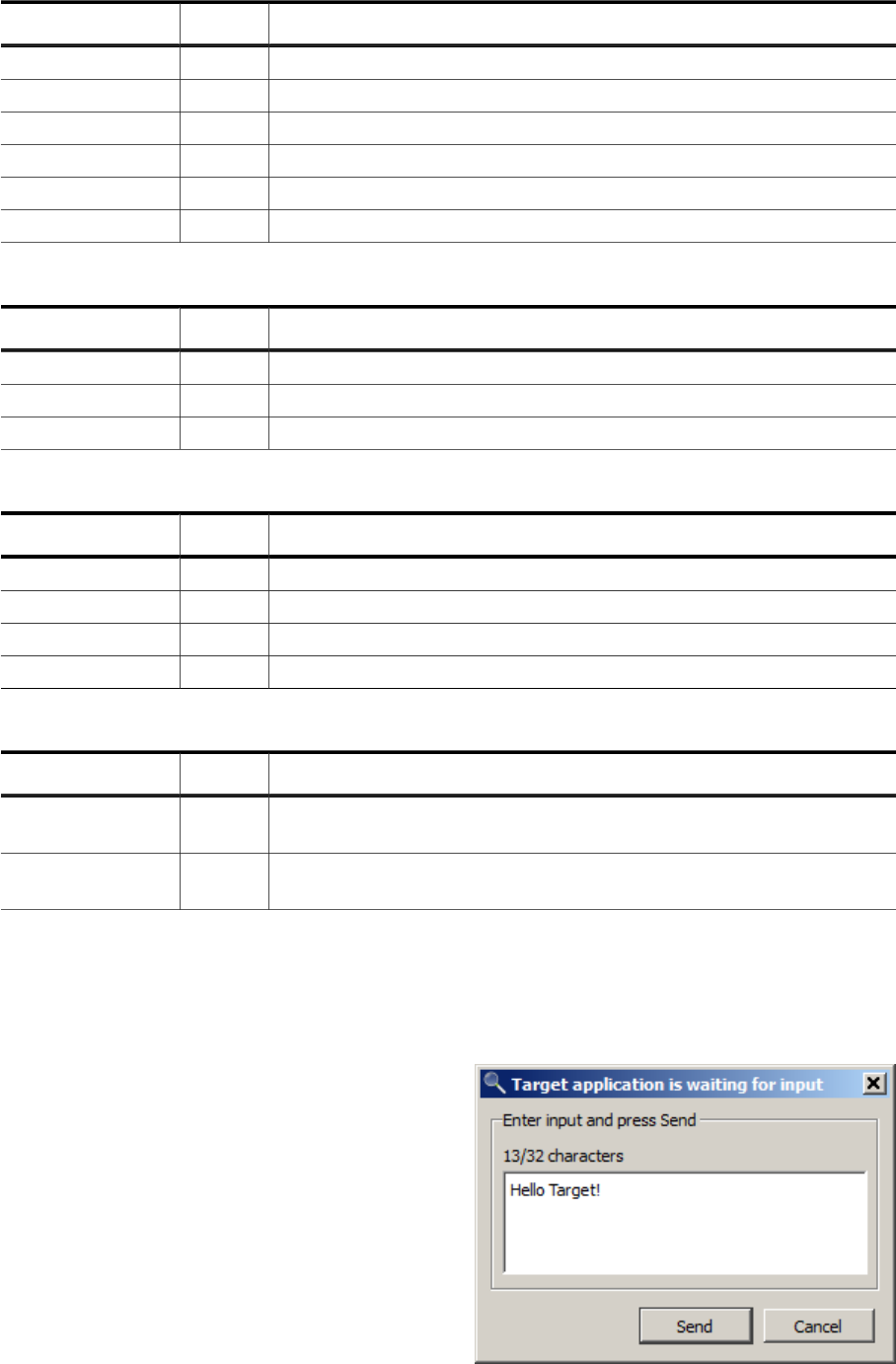
199 CHAPTER 5 Semihosting
Name Code Description
SysClose 0x2 Closes a file on the host which has been opened by SysOpen
SysFlen 0xC Get the byte size of a file
SysSeek 0xA Set the file cursor to a given position in a file
SysTmpNam 0xD Get a temporary absolute file path to create a temporary file
SysRemove 0xE Remove a file on the host system
SysRename 0xF Rename a file on the host system
Terminal I/O operations
Name Code Description
SysWriteC 0x3 Write one character to the debug terminal
SysWrite0 0x4 Write a 0-terminated string to the debug terminal
SysReadC 0x7 Read one character from the debug terminal
Time operations
Name Code Description
SysClock 0x10 Returns the system clock counter value
SysElapsed 0x30 Returns the clocks since debug session start
SysTickFreq 0x31 Returns the clocks per seconds
SysTime 0x11 Returns the current time
System / Misc operations
Name Code Description
SysErrno 0x13
Returns the value of the C library errno variable that is asso-
ciated with the semihosting implementation
SysGetCmdLine 0x15
Returns the command line parameters for the target applica-
tion to run with (argc and argv for main())
For further information on the legacy operations, including their parameter definitions, refer
to the ARM information center.
5.12.4 Input Operations
The debuggee may request user input via the
following semihosting operations supported
by Ozone:
• SysReadC and
• SysRead with IsTtyHandle(R1)==1
Users may serve input requests by:
• entering text into the terminal window’s
input field and pressing enter or
• by entering text into a popup dialog.
The input mode can be configured via setting
InputViaTerminal=0/1, as described in sec-
tion Semihosting Configuration on page 200.
Ozone User Guide & Reference Manual (UM08025) © 2013-2024 SEGGER Microcontroller GmbH
200 CHAPTER 5 Semihosting
5.12.5 Unsafe Operations
The following group of semihosting operations are classified to be unsafe:
• SysOpen
• SysRemove
• SysRename
These operations can potentially damage the host system. Each time an unsafe operation is
requested by the debuggee, Ozone will ask the user for permission to perform the operation
via a popup dialog. Individual permission dialogs can be suppressed. As an example, op-
eration SysRename can be suppressed via setting AllowRename=0, as described in section
Semihosting Configuration on page 200.
5.12.6 Semihosting Configuration
Ozone’s semihosting functionality can be configured in two ways:
• using command Project.ConfigSemihosting
• using the Semihosting Settings Dialog
A detailed description of each setting is given by section Project.ConfigSemihosting on
page 337.
5.12.7 Starting and Stopping Semihosting
Ozone automatically enables semihosting when the debug session is started. No user in-
teraction is required. However, it is recommended to disable semihosting when it is not
needed for performance reasons. To disable semihosting, the settings ModeBP, ModeBKPT
and ModeSVC must be set to No, i.e. their highest allowed value
5.12.8 Generic Semihosting
SEGGER has defined the first instruction of function SEGGER_SEMIHOST_DebugHalt to be a
universal semihosting trap which is available on all supported target architectures, includ-
ing RISC-V. In order to catch this trap, Ozone sets a hidden breakpoint on the function
whenever it is implemented by the debuggee. In order to perform a semihosting request,
the debuggee simply calls this function with the desired operation code as first parameter
and the operation argument block pointer as second parameter.
/*********************************************************************
*
* SEGGER_SEMIHOST_DebugHalt()
*
* Function description
* Generic semihosting request function.
* The debugger may set a breakpoint on this function, handle the
* semihosting request, and return to the caller.
*
* Parameters
* a0: semihosting operation code
* a1: semihosting operation argument pointer
*
* Return value
* a0 if debugger is not connected.
* Semihosting operation result code if debugger is connected.
*/
int __attribute__((noinline)) SEGGER_SEMIHOST_DebugHalt(int a0, int a1) {
(void)a1; // Avoid unused parameter warning
return a0;
}
Ozone User Guide & Reference Manual (UM08025) © 2013-2024 SEGGER Microcontroller GmbH
201 CHAPTER 5 Working With Expressions
5.13 Working With Expressions
In Ozone, an expression is a term that combines symbol identifiers or numbers via arith-
metic and non-arithmetic operators and that computes to a single value or symbol. Ozone-
style expressions are for the most part C-language compliant with certain limitations as
described below.
5.13.1 Areas of Application
Expressions are used in the following areas:
• As monitorable entities within the Watched Data Window
(see Watched Data Window on page 175).
• As monitorable entities within the Quick Watch Dialog
(see Quick Watch Dialog on page 93).
• As traceable entities within the Data Sampling Window
(see Data Sampling Window on page 113).
• As specifiers for the data locations of data breakpoints
(see Data Breakpoints on page 191).
• As specifiers for the trigger conditions of conditional breakpoints
(see Advanced Breakpoint Properties on page 189).
• At the command prompt or within Project Scripts
(see Elf.GetExprValue on page 369).
• Within RTOS Awareness Plugins
(see Debug.evaluate on page 378).
• Within SmartView Plugins
(see Debug.evaluate on page 378).
5.13.2 Operands
The following list gives an overview of valid expression operands:
• Global and local variables (e.g. OS_Global, PixelSizeX)
• Variable members (e.g. OS_Global.pTask->ID, OS_Global.Time)
• Numbers (e.g. 0xAE01, 12.4567, 1000)
• Program defines (e.g. MAX_SPEED)
• Ozone variables & constants (e.g. VAR_ACCESS_WIDTH, FREQ_1_MHZ)
• User-defined constants (see Script.DefineConst on page 314)
5.13.3 Operators
The following list gives an overview of valid expression operators:
• Number arithmetic (+, -, *, /, %)
• Bitwise arithmetic (~, &, |, ^)
• Logical comparison (&&, ||)
• Bit-shift (>>, <<)
• Address-of (&)
• Size-of (sizeof)
• Number comparison (>, <, ≥, ≤, ==, !=)
• Pointer-operations (*, [], ->)
• Integer-operations (++, −−)
• Type-casts (see Type Casts on page 201)
The evaluation order of an expression can be controlled by bracketing sub-expressions.
5.13.4 Type Casts
The typecast operator “(<dest>)<src>” supports the following source and destination
types:
Ozone User Guide & Reference Manual (UM08025) © 2013-2024 SEGGER Microcontroller GmbH
202 CHAPTER 5 Working With Expressions
<src>
• Integers (e.g. 0x20000000)
• Program Variables (e.g. OS_Global)
• Members (e.g. OS_Global.Time)
<dest>
• Pointers and References (e.g. int* / Type& / Type*)
• Arrays (e.g. char[128] / Type[20])
• Base types (e.g. int / double)
Ozone User Guide & Reference Manual (UM08025) © 2013-2024 SEGGER Microcontroller GmbH

203 CHAPTER 5 Locating Missing Source Files
5.14 Locating Missing Source Files
This section discusses the handling of source code files that Ozone could not locate on the
file system.
5.14.1 Causes for Missing Source Files
When a source code file has been moved from its compile-time location to a different
directory on the file system, the debugger is (in most cases) not able to locate the file
anymore. Due to performance reasons, Ozone only performs a limited file system search
to locate unresolved source code files.
Invalid Root Path
A second reason why one or multiple source files might be missing is that the debugger was
not able to determine the program’s root path correctly. The program’s root path is defined
as the common directory prefix that needs to be prefixed to relative file paths specified
within the program file.
5.14.2 Missing File Indicators
A missing source file is indicated by a warning sign within the Source Files Window. Addi-
tionally the Source Viewer will display an informative text instead of file contents when
the program’s execution point is within a missing source code file. The context menu of
missing source files provide an entry that lets users open a file dialog to locate the file (see
Unresolved Source Files on page 153.
5.14.3 File Path Resolution Sequence
This section describes Ozone’s automatic file path resolution mechanism that is employed
whenever a file path argument is encountered that does not point to a valid file or folder
on the file system.
The file path resolution sequence can be configured via script commands which enables
users to correct the file paths of missing source code files.
File path resolution is employed for all file types and is not restricted to source files. The
sequence of operations and its configuration options are described below. For a generic
overview about file path argument handling, see File Path Arguments on page 216.
Note
The root of relative file paths is the project file directory. If the project file directory
is not available, the system’s current working directory is used instead.
Step 1 - Source File Name Lookup
Step 1 of file path resolution is only applied to plain source file name input (e.g. "main.c"). A
lookup of the source file name is performed within the contents of the source files window.
If a source file with the given name is found, resolution is complete.
Step 2 - Path Substitution
Step 2 of the file path resolution sequence is applied to source files paths only. Any parts
of the unresolved file path that match a user-set path substitute are replaced with the
substitute (see Project.AddPathSubstitute on page 343). If the file path obtained from
path substitution points to a valid file on the file system, resolution is complete.
Ozone User Guide & Reference Manual (UM08025) © 2013-2024 SEGGER Microcontroller GmbH
204 CHAPTER 5 Locating Missing Source Files
Step 3 - Alias Name Substitution
If the user has specified an alias for the file path to resolve, the path is replaced with the
alias (see Project.AddFileAlias on page 342). If the alias points to a valid file on the file
system, resolution is complete.
Step 4 - Path Expansion
All directory macros and environment variables contained within the file path are expanded
(see Directory Macros on page 273). If the expanded file path points to a valid file on the
file system, resolution is complete.
Step 5 - Source File Root Paths
Step 5 of file path resolution is only applied to unresolved relative file paths. These are ap-
pended successively to each source file root path (see Project.AddRootPath on page 342).
If any of the so-obtained file paths points to a valid file on the file system, resolution is
complete.
Step 6 - Application Directories
Step 6 of file path resolution is only applied to unresolved relative file paths. These are
appended successively to each of the application directories listed in Directory Macros on
page 273. If any of the so-obtained file paths points to a valid file on the file system,
resolution is complete.
Step 7 - Search Directories
Step 7 of file path resolution is applied to both absolute and relative file paths. The file
name of unresolved file paths is searched within all user-specified search directories (see
Project.AddSearchPath on page 343). If any of the search directories contains a file with
the sought name, resolution is complete.
5.14.4 Operating System Specifics
File path arguments are case-insensitive on Windows and case sensitive on Linux and ma-
cOS. When debugging an application on a system that differs from the build platform, ad-
justments to the project file’s path resolution settings might be required in order for the
debugger to be able to locate all files.
Ozone User Guide & Reference Manual (UM08025) © 2013-2024 SEGGER Microcontroller GmbH

205 CHAPTER 5 Setting Up The Instruction Cache
5.15 Setting Up The Instruction Cache
All instruction-level debug features of Ozone require the debugger to perform an initial
analysis of the machine code to be debugged.
In cases where:
• the debuggee’s machine code is fully accessible from the program file,
• the debuggee’s machine code is fully accessible from target memory at the Startup
Completion Point,
the debugger will perform this analysis automatically and no user interaction is required.
In all other cases, e.g. when:
• a non-ELF program file is specified,
• a secondary program image is in use, such as a bootloader,
parts of the instruction cache may need to be initialized manually. For this purpose,
Ozone provides the command Debug.ReadIntoInstCache (see Debug.ReadIntoInstCache
on page 328). The preferred way to employ this command is to call it from project script
function OnStartupComplete.
Instruction-level debug information which is unavailable due to an incompletely initialized
instruction cache is indicated by a warning sign.
When the instruction cache misses data for a particular code address range, Ozone will
display a warning sign next to all affected GUI elements as shown above.
Ozone User Guide & Reference Manual (UM08025) © 2013-2024 SEGGER Microcontroller GmbH

206 CHAPTER 5 Setting Up Trace
5.16 Setting Up Trace
This section describes the configuration of trace within Ozone. For a general overview on
trace with J-Link and J-Trace, please refer to the J-Link User Guide and SEGGER’s website .
5.16.1 Trace Features Overview
Ozone’s trace features consist of the following elements:
• Instruction Trace Window (see Instruction Trace Window on page 128)
• Timeline Window (see Timeline Window on page 164)
• Code Profile Window (see Code Profile Window on page 105)
• Execution Counters (see Code Execution Counters on page 54)
5.16.2 Target Requirements
Ozone currently supports trace on the following MCU architectures:
• Cortex-M
• Cortex-A
ARM’s Cortex MCU architecture principally enables two ways how trace data may be moved
from the target to the PC: in a buffered (ETB) and a streaming (ETM) fashion. ETM trace
has many advantages over ETB trace but also an extended hardware requirement (see
Streaming Trace on page 194).
5.16.2.1 Target Requirements for ETB Trace
Buffered trace requires the target to contain an embedded trace buffer (ETB). The trace
buffer must be accessible to J-Link/J-Trace, i.e. accessible via the selected target interface.
ETB-Trace otherwise poses no additional requirements on the hardware setup.
5.16.2.2 Target Requirements for ETM Trace
Streaming trace requires the target CPU to contain an embedded trace macrocell (ETM) or
a program trace macrocell (PTM). The trace data generated by these units is emitted via
dedicated CPU pins. It is target dependent if these trace pins are present and to what type
of debug header they are connected, if any. Most commonly, the trace pins are routed to
a 19-pin Samtec FTSH “trace” header.
5.16.3 Debug Probe Requirements
• ETB trace is supported by all J-Link and J-Trace models.
• ETM trace requires a J-Trace PRO model to be employed.
5.16.4 Trace Settings
• ETB trace does not need to be configured in Ozone.
• ETM trace has multiple configuration settings which can be edited via the Trace Settings
Dialog (see Trace Settings Dialog on page 83) or via debugger commands as shown
below.
Command Description Default
Project.SetTraceSource
Selects the trace source to use. See Trace
Sources on page 262 for the list of valid
values.
none
Project.SetTracePortWidth
Specifies the number of trace pins provid-
ed by the target. Permitted values are 1, 2
and 4.
4
Ozone User Guide & Reference Manual (UM08025) © 2013-2024 SEGGER Microcontroller GmbH

207 CHAPTER 5 Setting Up Trace
Command Description Default
Project.SetTraceTiming
Configures the sampling delay of trace pin
n (n=1…4). The valid value range is -5 to
+5 nanoseconds at steps of 50 ps. See
Project.SetTraceTiming on page 340 for
further information.
2.0ns
Edit.Sys-
Var(VAR_TRACE_MAX_INST_CNT)
Specifies the maximum number of instruc-
tions that Ozone can process and store
during a streaming trace session.
10M
Edit.SysVar(VAR_TRACE_TIMES-
TAMPS_ENABLED)
Specifies weather the target is to output
(and J-Link/Ozone is to process) PC time-
stamps multiplexed into the trace data
stream.
1
Edit.Sys-
Var(VAR_TRACE_CORE_CLOCK)
CPU frequency in Hz. Ozone uses this vari-
able to convert instruction timestamps
from CPU cycle count to time format (see
VAR_TRACE_TIMESTAMPS_ENABLED).
100kHz
Note
When instruction timestamps are not required, the option should be disabled to en-
hance the overall tracing performance.
Ozone User Guide & Reference Manual (UM08025) © 2013-2024 SEGGER Microcontroller GmbH

208 CHAPTER 5 Selective Tracing
5.17 Selective Tracing
5.17.1 Overview
Many ARM-Cortex targets allow trace data output to be limited to a set of user-defined
program address ranges. When selective tracing is active, the target’s trace buffer is only
filled with trace data that matches the configured constraints. This makes selective tracing
particularly valuable on hardware setups with limited trace buffer size and no streaming
trace capability.
5.17.2 Hardware Requirements
It is to a high degree target dependent if selective tracing is supported and to what extent.
A generic requirements overview cannot be given. Instead, refer to your MCU model’s user
manual or contact the manufacturer when unsure about the capabilities of your target.
Upon target connection, J-Link/J-Trace automatically detects if the target supports selective
tracing and enables the debugger to use the feature when available.
5.17.3 Tracepoints
Selective tracing is implemented in Ozone using start and stop-
type tracepoints. Tracepoints can be toggled on program instruc-
tions and source lines just like ordinary breakpoints. Each matching
pair of start and stop tracepoints marks an address range whose
instructions are included in the target’s trace output. All instruction
fetches occurring outside of tracepoint-configured address ranges
will not generate trace data.
Tracepoint Imprecision
An MCU possibly commands its tracepoints hardware unit asyn-
chronously to its instruction execution unit. This means that trace data capture may be
started and stopped a few cycles after the affiliated instruction has been fetched for exe-
cution.
5.17.4 Scope
All of the features summarized in Trace Features Overview on page 206 are affected by
selective tracing.
Ozone User Guide & Reference Manual (UM08025) © 2013-2024 SEGGER Microcontroller GmbH

209 CHAPTER 5 Advanced Program Analysis And Optimization
Hints
5.18 Advanced Program Analysis And Optimization
Hints
This section describes use-cases of advanced program analysis using the (streaming) in-
struction trace and code profiling capabilities of Ozone. For code profiling hardware require-
ments, see Hardware Requirements on page 208.
5.18.1 Program Performance Optimization
5.18.1.1 Scenario
The user wants to optimize the runtime performance of the debuggee.
To get an overview of the program functions in which most CPU time is spent, it is usually
good to start by looking at the Code Profile Window and to sort its functions list according
to CPU load:
Filtering Functions
In this example, the program spends 99% of its CPU time in the idle loop, which is not
relevant for optimizations. To get a clear picture about where the rest of the CPU time
is spent, the idle loop can be filtered from the code profile statistic. This can be done by
selecting function OS_Idle and clicking on the context menu entry “Exclude”.
Filtering Instructions
A compiler may furthermore emit code alignment instructions (NOP’s) that are likewise
not relevant for code optimization. NOP Instructions can be filtered from the code profile
statistic by clicking on context menu entry “Exclude NOP Instructions” or via command
Coverage.ExcludeNOPs (see Coverage.ExcludeNOPs on page 348).
After filtering, the Code Profile Window shows where the application spends the remaining
CPU time. Other functions which affect the CPU load but cannot be optimized any further
can be filtered accordingly in order to find remaining functions worth optimizing. In this
example, a quarter of the remaining CPU time is spend in function vTraceStoreEvent1. Let’s
now assume the user wants to optimize the runtime of this function. By double-clicking on
the function, the function is displayed within the Source Viewer.
Evaluating Execution Counters
The Source Viewer’s execution counters indi-
cate that an assertion macro within function
vTraceStoreEvent1 has been executed a signif-
icant amount of times. The Source Viewer also
Ozone User Guide & Reference Manual (UM08025) © 2013-2024 SEGGER Microcontroller GmbH

210 CHAPTER 5 Advanced Program Analysis And Optimization
Hints
indicates that the last 3 instructions of the assertion macro have never been executed. This
means that the assertion was always true when it was evaluated.
Deriving Improvement Concepts
At this point, the user could think about removing the assertion or ensuring that the asser-
tion is only evaluated when the program is run in debug mode.
Impact Estimation
To get an idea of the impact of the optimization, the execution counters may provide a first
idea. In general, optimizing source lines which are executed more often can result in higher
optimization. If the function code is fully sequential, i.e. if there are no loops or branches
in the code, the impact can be estimated exactly.
Code Profile Status Information
The status information of the Code Profile Window displays the target’s actual instruction
execution frequency. An instructions per second value that is significantly below the target’s
core frequency may indicate that the target is thwarted by an excessive hardware IRQ load.
Ozone User Guide & Reference Manual (UM08025) © 2013-2024 SEGGER Microcontroller GmbH
211 CHAPTER 5 Debug Snapshots
5.19 Debug Snapshots
The debug session and affiliated system state can be saved to / restored from a session
file called debug snapshot. This includes:
• RAM
• Flash
• CPU registers
• Selected Peripherals
• Timeline
• Code Profile (Execution Counters)
• Data Graphs
• Power Graphs
• Terminal Log
• Console Log
Snapshots are saved and loaded using the Snapshot Dialog (see Snapshot Dialog on
page 78). After loading a snapshot, all debug windows show the same information they did
at the time the snapshot has been created. Snapshots can be loaded and observed in tar-
get-offline mode. This means that no hardware is required to load a snapshot, not even a J-
Link or J-Trace. Snapshots are compressed using SEGGER’s emCompress software library.
5.19.1 Use Cases
Typical use cases of snapshots are:
• Snapshots allow customers to break away from a debug session with the ability to
resume the session at a later point in time.
• Snapshots allow easier reproduction and analysis of bugs, possibly by multiple parties
on different Host-PCs.
• Snapshots enhance Ozone’s teaching and demonstration capabilities in training sessions
and conferences.
5.19.2 Supported Architectures
Snapshots are currently supported on the following target architectures:
• Cortex-M
5.19.3 Default System Restore
When a snapshot is loaded, target CPU registers and memory regions are restored in the
order they appear within the snapshot. This order is identical to the order that was displayed
by the Snapshot Dialog at the time the snapshot was saved. The default system state saved
to snapshots consists of:
• all basic CPU registers, including FP registers.
• all FLASH and RAM regions of the target as defined by J-Link’s MCU database.
• all ELF program data sections with the allocatable flag (A) set.
5.19.4 Advanced System Restore
In order to restore advanced system state such as (clocked) peripherals from a snapshot,
it is generally necessary for users to program the exact sequence of restore operations.
For this reason, any system or peripheral register stored within a snapshot is not automat-
ically written to the target when a snapshot is loaded. Instead, users must program the
specific way in which special-purpose registers are saved to and restored from snapshots
as explained in section Snapshot Programming on page 249.
Ozone User Guide & Reference Manual (UM08025) © 2013-2024 SEGGER Microcontroller GmbH
212 CHAPTER 5 Debug Snapshots
5.19.5 The Scope of Snapshots
Snapshot store binary debug session data which cannot be easily or efficiently stored in
a user-readable format. Snapshots do not replace any of Ozone’s existing configuration
facilities. In particular, snapshots do not store nor replace:
• Project settings such as Project.SetDevice or Target.PowerOn.
• User file settings such as breakpoints and open documents.
• User preferences and GUI settings.
Ozone User Guide & Reference Manual (UM08025) © 2013-2024 SEGGER Microcontroller GmbH

213 CHAPTER 5 Remote Debugging
5.20 Remote Debugging
Ozone can connect to a remote J-Link/J-Trace debug probe to debug on a remote target.
When debugging remotely, the J-Link/J-Trace debug probe is connected to a remote PC via
the Ethernet host interface.
5.20.1 Remote Debugging Over LAN
When the remote PC is on the same LAN as the PC hosting Ozone (host PC), it suffices to
start a J-Link Remote Server on the remote PC and supply the IP address of the remote
server within Ozone’s Host Interface Dialog (instead of the IP of the J-Link / J-Trace de-
bug probe). The Host Interface Dialog is accessible via Ozone menu path Tools->J-Link
Settings->Host Interface. Note that J-Link Remote Server V6.53b and later also supports
encrypted connections.
5.20.2 Remote Debugging Over The Internet
When the remote PC is not on the same LAN as the host-PC, an intermediary tunnel server
at SEGGER can be used to be mediate a connection for remote debugging. Both Ozone
and the J-Link Remote Server then connect to this tunnel server instead of connecting to
each other directly.
For remote debugging via the J-Link Tunnel Server, the IP address field of Ozone’s host
interface dialog expects a tunnel server credential of the form:
tunnel:<Probe>[:<Password>[:<Server>]]
where:
Argument Description
Probe
Either the serial number or nickname of the J-Link / J-Trace to con-
nect to.
Password
Password that was used when the J-Link / J-Trace debug probe was
registered with the Remote Server.
Server
Address or hostname of the tunnel server. For use when a tun-
nel server other than the SEGGER default tunnel server (jlink.seg-
ger.com, port 19020) is used.
Ozone User Guide & Reference Manual (UM08025) © 2013-2024 SEGGER Microcontroller GmbH

214 CHAPTER 5 Remote Debugging
The short credential variant tunnel:<Probe> can be used when the connection is to be
established to the default J-Link Tunnel Server and is not password-protected. When de-
bugging via the tunnel server, make sure that port 19020 is not blocked by a firewall.
Examples
Input Description
tunnel:932000:Pass123:jlink.segger.com
J-Link was registered by S/N, with a pass-
word, at jlink.segger.com
tunnel:MyJLink::jlink2.segger.com
J-Link was registered by Name, without a
password, at jlink2.segger.com
tunnel:600100000:MyPassword123
J-Link was registered by S/N, with a pass-
word, at the default tunnel server.
Ozone User Guide & Reference Manual (UM08025) © 2013-2024 SEGGER Microcontroller GmbH

215 CHAPTER 5 Messages And Notifications
5.21 Messages And Notifications
This section provides a brief description of Ozone’s application message and user notification
system.
5.21.1 Message Format
The format of Ozone application messages is <type>(<code>): <message>, where <type>
is either error or warning and <code> is a unique message number.
5.21.2 Message Codes
Section Errors and Warnings on page 275 lists all user-visible error and warning messages
by their code and provides an overview of the cause and possible solution to each exception.
5.21.3 Logging Sinks
Application messages are output to any of the following destinations:
• Ozone’s Console Window
• Debug Console
• Application Logfile
Application messages printed to the Console Window have the highest priority and become
immediately noticeable to the user.
The allocation of message types to logging sinks is depicted in the table below.
Message Type Ozone Console Debug Console Logfile
Error x x x
Warning (important) x x x
Info (important) x x x
Warning x x
Info x x
5.21.4 Debug Console
When Ozone is started with command line argument -debug, a debug console will open
next to the Main Window. The debug console displays all application messages of lower
significance that would otherwise only be visible to the software developer.
5.21.5 Application Logfile
The global logfile storing all application messages is disabled per default. It can be enabled
via command line argument -logfile <path> (see Command Line Arguments on page 271).
5.21.6 Other Logfiles
Messages output to the Console Window or Terminal Window can additionally be logged to
a separate logfile (see Project.SetConsoleLogFile on page 344 and Project.SetTerminal-
LogFile on page 345).
Ozone User Guide & Reference Manual (UM08025) © 2013-2024 SEGGER Microcontroller GmbH
216 CHAPTER 5 File Path Arguments
5.22 File Path Arguments
This section explains the rules pertaining to file path input.
Ozone obtains user file path input via multiple channels, such as:
• export dialogs
• command arguments
• console prompt
Regardless of the input channel, a file path argument is processed in the following globally
consistent way:
• A file path may be specified either as an absolute or as a relative path. In the latter
case, the path is relative to the project file directory. If the project file directory does
not exist, the path is relative to the system’s current working directory.
• File path arguments may include Ozone directory macros, environment variables and
cd-up (..) macros (see Directory Macros on page 273 and Environment Variables on
page 273).
• User preference PREF_AUTO_CREATE_DIR_PATHS governs if the output directory path will
be automatically created when it does not exist.
• The letter casing of file paths is only relevant on macOS and Linux.
• A file path must end with a file name and a file extension. The file extension can be
omitted when explicitly indicated within this user guide.
• Every time Ozone encounters an invalid file path argument that does not point to a
file or directory, the debugger tries to resolve the file path as described in File Path
Resolution Sequence on page 203. When the path could be successfully resolved, it
replaces the user input.
Ozone User Guide & Reference Manual (UM08025) © 2013-2024 SEGGER Microcontroller GmbH
217 CHAPTER 5 Other Debugging Activities
5.23 Other Debugging Activities
This section describes all debugging activities that were not covered by the previous sec-
tions.
5.23.1 Finding Text Occurrences
Text patterns within source code documents may be located using the Find In Files Dialog
(see Find In Files Dialog on page 69). This dialog supports regular expressions and standard
text search options.
Text patterns within the content of the Instruction Trace Window may be located using the
Find In Trace Dialog (see Find In Trace Dialog on page 71). This dialog supports regular
expressions and standard text search options.
When a text pattern is to be found within the active document, users may furthermore
resort to the convenient Quick Find Widget (see Quick Find Widget on page 91). The
quick find widget can be used alternatively to locate a particular function, global variable
or source code file of the debuggee.
The Find In Trace Dialog is provided to locate text patterns within Instruction Trace Window
content.
5.23.2 Saving And Loading Memory
Ozone enables users to store target memory content to a binary data file and vice versa.
Memory-To-File
Target memory blocks can be saved (dumped) to a binary data file via command Tar-
get.SaveMemory (see Target.SaveMemory on page 353) or via the Save Memory Dialog
(see Memory Dialog on page 137).
File-To-Memory
File contents can be downloaded to target memory via command Target.LoadMemory (see
Target.LoadMemory on page 353) or via the Load Memory Dialog (see Memory Dialog on
page 137).
5.23.3 Relocating Symbols
To allow the debugging of runtime-relocated programs such as bootloaders, Ozone pro-
vides command Project.RelocateSymbols (see Project.RelocateSymbols on page 344).
This command shifts the absolute addresses of a set of program symbols by a constant
offset. It can thus be used to realign symbol addresses to a modified program base address.
Symbol relocation must be specified before the program file is opened.
5.23.4 Closing the Debug Session
The debug session can be closed via command Debug.Stop (see Debug.Stop on page 323).
The action can be executed from the Debug Menu or by pressing the hotkey Shift-F5.
5.23.5 Interworking with External Applications
Ozone can spawn processes and execute external applications. The exit code of the ap-
plication can be used in Ozone for further processing and textual poutput created by the
application on standard output channels (such as stdout and stderr) is captured and dis-
played in Ozone’s console window. The preferences dialog allows specifying the colors for
such messages in the console window.
A timeout duration can be specified. If the application does not terminate within that time
limit, the application is killed by Ozone.
Ozone User Guide & Reference Manual (UM08025) © 2013-2024 SEGGER Microcontroller GmbH
218 CHAPTER 5 Other Debugging Activities
Applications can be launched in 2 ways:
• Waiting for termination: The application is started and Ozone waits until the
application terminates. Ozone supports starting only a single process at a time this way.
Another application can be started only after the previous application terminated.
• Fire-and-forget: The application is started without Ozone waiting for its termination.
The exit code of the application is not available in Ozone and textual outputis neither
captured nor displayed in the console window. Multiple applications can be started this
way at the same time.
For this feature the command Process.Exec (see Process.Exec on page 330) is used. When
launching the application, the following information must be provided:
• The application’s name as it is used to start the application from the OS shell’s
command line. The path information may be included.
• The argument list as it would be specified when starting the application from the OS
shell. The argument list must be provided in a single string containing all arguments
separated by whitespaces.
• The Timeout. This is the expected execution time in milliseconds after which the
process will be killed in case the application did not termiante beforehand.
Quotes in the file name and/or arguments need to be escaped with a preceeding backslash,
i.e. ’\“’ must be used.
Ozone User Guide & Reference Manual (UM08025) © 2013-2024 SEGGER Microcontroller GmbH

Chapter 6
Scripting Interface
This chapter describes Ozone’s scripting interface. The scripting interface enables users to:
• reprogram key debug operations
• incorporate a bootloader into Ozone’s startup sequence
• extend Ozone’s target application insight via RTOS awareness plugins
• support custom instructions
among other applications.
Ozone User Guide & Reference Manual (UM08025) © 2013-2024 SEGGER Microcontroller GmbH

220 CHAPTER 6 Project Script
6.1 Project Script
Ozone project scripts (*.jdebug) contain user-implemented script functions that the de-
bugger executes upon entry of defined events or debug operations. By implementing script
functions, users are able to reprogram key operations within Ozone such as the hardware
reset sequence that puts the target into its initial state.
It is also possible to use functions inside the project script as macros for complex command
sequences. For details please refer to User Functions on page 221.
6.1.1 Script Language
Ozone project scripts are written in a simplified C language that supports most C language
constructs such as functions and control structures.
Types
The following types and type definitions can be used within project scripts:
int __int64 U64 I64
short __int32 U32 I32
char __int16 U16 I16
void __int8 U8 I8
as well as pointers to − and arrays of − the types listed above.
Type Modifiers
The following type modifiers can be used within project scripts:
• signed
• unsigned
• static
• const
Operators
Ozone project scripts support all binary and unary C operators with the exception of the
unary increment and decrement operators.
Syntax Constraints
The following syntax constraints apply to project scripts:
• variables must be declared before they can be initialized.
• local variable declarations have to be placed on top of the function body before all other
code.
• quotes in strings need to be escaped with a preceeding backslash.
6.1.2 Script Structure
On a top level, there are 3 structural elements within a project script:
Global Variable Declarations
static unsigned int _PC;
Constant Value Definitions
__constant unsigned int PC_OFFSET = 4;
Function Definitions
void AfterTargetReset(void) {
Ozone User Guide & Reference Manual (UM08025) © 2013-2024 SEGGER Microcontroller GmbH

221 CHAPTER 6 Project Script
Target.WriteU32(0x40004002, 0xFF);
}
All other script code must be contained within script functions. In addition, global constants
can be defined using command Script.DefineConst (see Script.DefineConst on page 314).
6.1.3 Script Functions Overview
Project file script functions belong to three different categories: event handler functions,
process replacement functions and user functions. Each script function may contain C code
that configures the debugger in some way or replaces a default operation of the debugging
workflow. The different function categories are described below.
6.1.4 Event Handler Functions
Ozone defines a set of event handler functions that the debugger executes upon entry of
specific debug events. The Table below lists the event handler functions and their associated
events. The event handler function OnProjectLoad must be present in a project file. All
other functions are optional.
Event Handler Function Description
void OnProjectLoad(); Executed when the project file is opened.
void AfterProjectLoad(); Executed after the project file is opened.
void OnStartupComplete();
Executed when the Startup Completion Point was
reached.
void BeforeTargetReset(); Executed before the target is reset.
void AfterTargetReset(); Executed after the target was reset.
void BeforeTargetDownload(); Executed before the program file is downloaded.
void AfterTargetDownload(); Executed after the program file was downloaded.
void BeforeTargetConnect();
Executed before a connection to the target is estab-
lished.
void AfterTargetConnect();
Executed after a connection to the target was es-
tablished.
void BeforeTargetDiscon-
nect();
Executed before the debugger disconnects from the
target.
void AfterTargetDiscon-
nect();
Executed after the debugger disconnected from the
target.
void AfterTargetHalt(); Executed after the target processor was halted.
void BeforeTargetResume(); Executed before the target processor is resumed.
void OnSnapshotLoad(); Executed when a debug snapshot is loaded.
void OnSnapshotSave(); Executed when a debug snapshot is saved.
void OnError(char* sEr-
rorMsg);
Executed when an error occurred.
6.1.5 User Functions
Users are free to add custom functions to the project file. These “helper” or user functions
are not called by the debugger directly; instead, user functions need to be called from other
script functions.
User functions can also be called via the command Script.Exec (to be entered into the Com-
mand Prompt in the Console Window), or via the Custom Toolbar. Thus user functions may
serve as macros for complex sequences of steps: The sequence needs to be implemented
Ozone User Guide & Reference Manual (UM08025) © 2013-2024 SEGGER Microcontroller GmbH

222 CHAPTER 6 Project Script
into a user function so it can be executed each time the respective button in the Custom
Toolbar is clicked.
User functions may also be linked to a break point, so they are invoked each time the
breakpoint is taken. This can be used for automation purposes but also for smarter trig-
gering, by evaluating complex conditions inside the function and resuming execution of the
target in case they are not met. Details on that topic can be found in the section Breakpoint
Callback Functions on page 190.
6.1.6 Debugger API Functions
In the context of project script files, any user action that has a text command is referred to
as an API function or API command (see Action Tables on page 42). API functions can be
called from project script files to execute specific functions of the debugger and to exchange
data with the debugger. In short, API functions resemble the debugger’s programming
interface (or API).
6.1.7 Process Replacement Functions
Ozone defines 4 script functions that can be implemented within the project file to replace
the default implementations of certain debug operations. The behavior that is expected
from process replacement functions is described in this section.
Process Replacement Function Description
void DebugStart(); Replaces the default debug session startup routine.
void TargetReset(); Replaces the default target hardware reset routine.
void TargetConnect(); Replaces the default target connection routine.
void TargetDownload(); Replaces the default program download routine.
6.1.7.1 DebugStart
When script function DebugStart is present in the project file, the default startup sequence
of the debug session is replaced with the operation defined by the script function.
Startup Sequence
The table below lists the different phases of Ozone’s default debug session startup sequence
(see Download & Reset Program on page 182). The last column of the table indicates the
process replacement function that can be implemented to replace a particular phase of the
startup sequence. The complete startup sequence can be replaced by implementing the
script function DebugStart.
Startup Phase Description
Process Replacement
Function
Phase 1: Connect
A connection to the target is estab-
lished via J-Link/J-Trace.
TargetConnect
Phase 2: Breakpoints
Pending (data) breakpoints that were
set in offline mode are applied.
Phase 3: Reset
A hardware reset of the target is per-
formed.
TargetReset
Phase 4: Download
The debuggee is downloaded to target
memory.
TargetDownload
Phase 5: Finish
The initial program operation is per-
formed (see Initial Program Operation
on page 182).
Ozone User Guide & Reference Manual (UM08025) © 2013-2024 SEGGER Microcontroller GmbH
223 CHAPTER 6 Project Script
Flow Chart
Appendix Startup Sequence Flow Chart on page 274 provides a graphical flowchart of
the startup sequence. Most notably, the flowchart illustrates at what points during the
startup sequence certain event handler functions are called (see Event Handler Functions
on page 221).
Breakpoint Phase
Phase 2 (Breakpoints) of the default startup sequence is always executed implicitly after
the connection to the target was established.
Writing a Custom Startup Routine
A custom startup routine that performs all phases of the default sequence but the initial
program operation is displayed below.
void DebugStart (void) {
Exec.Connect();
Exec.Reset();
Exec.Download("C:/examples/keil/stm32f103/blinky.axf");
}
6.1.7.2 TargetConnect
When script function TargetConnect is present in the project file, the debugger’s default
target connection behavior is replaced with the operation defined by the script function.
6.1.7.3 TargetDownload
When script function TargetDownload is present in the project file, the debugger’s default
program download behavior is replaced with the operation defined by the script function.
Writing a Multi-Image Download Routine
An application that requires the implementation of a custom download routine is when
one or multiple additional program images (or data files) need to be downloaded to target
memory along with the debuggee. A corresponding implementation of the script function
TargetDownload is illustrated below.
/*********************************************************************
*
* TargetDownload
*
* Function description
* Downloads an additional program image to target memory
*
**********************************************************************
*/
void TargetDownload(void) {
Util.Log("Downloading Program.");
// 1. Download the debuggee
Exec.Download();
// 2. Download the additional program image
Target.LoadMemory("C:/AdditionalProgramData.hex", 0x20000400);
}
Using command “Exec.Download” to perform the download guarantees that there will be
no script function recursion (see Download Behavior Comparison on page 195).
Ozone User Guide & Reference Manual (UM08025) © 2013-2024 SEGGER Microcontroller GmbH
224 CHAPTER 6 Project Script
6.1.7.4 TargetReset
When script function TargetReset is defined within the project file, the debugger’s default
target hardware reset operation is replaced with the operation defined by the script function.
J-Link Reset Routine
Ozone’s default hardware reset routine is based on the J-Link/J-Trace firmware routine
“JLINKARM_Reset”. Please refer to the J-Link User Guide for details on this routine and
its target-dependent behavior.
Writing a Reset Routine for RAM Debug
A typical example where the J-Link/J-Trace hardware reset routine must be replaced with
a custom reset routine is when the debuggee is downloaded to a memory address other
than zero, for example the RAM base address.
Problem
The standard reset routine of the firmware assumes that the debuggee’s vector table is
located at address 0 (Cortex-M) or that the initial PC is 0 (Cortex-A/R, Legacy ARM). As this
is not true for RAM debug, the reset routine must be replaced with a custom implementation
that initializes the PC and SP registers to correct values.
Solution
A custom reset routine for RAM debug typically first executes the default J-Link hardware
reset routine. This ensures that tasks such as pulling the target’s reset pin and halting the
processor are performed. Next, a custom reset routine needs to initialize the PC and SP
registers so that the target is ready to execute the first program instruction.
Example
The figure below displays the typical implementation of a custom hardware reset routine
for RAM debug on a Cortex-M target. This implementation is included in all project files
generated by the Project Wizard that are set up for a Cortex-M target device.
/*********************************************************************
*
* TargetReset
*
* Function description
* Resets a program downloaded to a Cortex-M target’s RAM section
*
**********************************************************************
*/
void TargetReset(void) {
unsigned int SP;
unsigned int PC;
unsigned int ProgramAddr;
Util.Log("Performing custom hardware reset for RAM debug.");
ProgramAddr = 0x20000000;
// 1. Perform default hardware reset operation
Exec.Reset();
// 2. Initialize SP
SP = Target.ReadU32(ProgramAddr);
Target.SetReg("SP", SP);
// 3. Initialize PC
PC = Target.ReadU32(ProgramAddr + 4);
Target.SetReg("PC", PC);
}
Ozone User Guide & Reference Manual (UM08025) © 2013-2024 SEGGER Microcontroller GmbH
225 CHAPTER 6 Project Script
6.1.8 Executing Script Functions
Ozone provides the command Script.Exec (see Script.Exec on page 314) that enables
users to execute individual project script functions from the Command Prompt (see Com-
mand Prompt on page 110).
Ozone User Guide & Reference Manual (UM08025) © 2013-2024 SEGGER Microcontroller GmbH

226 CHAPTER 6 Disassembly Plugin
6.2 Disassembly Plugin
A disassembly plugin adds support for custom instructions to Ozone. It enables users to
debug and analyze a program containing custom instructions without limitations.
In particular, a disassembly plugin:
• enables the disassembly of custom instructions within the Disassembly Window (see
Disassembly Window on page 117).
• enables all features of Ozone that rely on numerical instruction information to process
custom instructions and output accurate results.
An example for the latter case is the Call Graph Window. This debug window requires
knowledge about the branch destination PC for all branch-type instructions in order to build
function call graphs.
6.2.1 Script Language
Disassembly plugins are written in JavaScript. All of JavaScript’s basic language constructs
are supported. The following restrictions apply:
• All script code must be contained within functions.
• Exception handling (throw, try, catch) is not supported.
6.2.2 Loading the Plugin
Command Project.SetDisassemblyPlugin loads a disassembly plugin. When this command
is added to project script function OnProjectLoad, the plugin will be loaded each time the
project is opened (see Project.SetDisassemblyPlugin on page 334).
Users may alternatively execute action Set Script of the disassembly window context menu
in order to load a disassembly plugin. When executed, this action will also edit the project
file accordingly.
6.2.3 Script Functions Overview
A disassembly plugin consists of 3 predefined functions:
Function Description Executed When
init performs initialization tasks plugin load
printInstAsm
Returns the disassembly text of a custom (or over-
ridden) instruction
on-demand
getInstInfo
Returns numeric information about a custom (or
overridden) instruction, such as the PC branched to
program file
load
The implementation of each function is optional.
Next to the predefined script functions, users are free to add their own functions to disas-
sembly plugins in order to structure the code.
6.2.4 Debugger API
Ozone defines a set of commands that can be called from disassembly plugins to communi-
cate and exchange data with the debugger. These commands are implemented as methods
of Ozone’s JavaScript API classes:
Class Description
Debug Provides methods that query information from the debugger.
TargetInterface Provides methods that read or write target memory and registers.
Ozone User Guide & Reference Manual (UM08025) © 2013-2024 SEGGER Microcontroller GmbH

227 CHAPTER 6 Disassembly Plugin
The following API commands are of particular importance for the development of disas-
sembly plugins:
Command Description Typical Application
Debug.enableOverrideInst
Overrides a known in-
struction
called from function init
Debug.getSymbol
Returns the name of a
symbol
Obtain the label of a branch
instruction
TargetInterface.peekBytes
Reads target memory
data
Obtain the word at the ac-
cess location of a load/store
instruction
An example-based description of the API classes can be found in section Writing the Dis-
assembly Plugin on page 227. A formal description is given by section JavaScript Classes
on page 375.
6.2.5 Writing the Disassembly Plugin
This section provides an example implementation which adds support for a custom instruc-
tion on a RI5CY RISC-V MCU core.
6.2.5.1 init
A disassembly plugin implementation typically starts with script function init. This function
is called when the disassembly plugin is loaded. The main purpose of function init is to
provide a place where instruction overrides using command Debug.enableOverrideInst
can be defined. An instruction override enables users to alter the disassembly and numerical
information of a known instruction.
/*********************************************************************
*
* init
*
* Function Description
* Called by Ozone when the script was loaded
* (i.e. when command “Project.SetDisassemblyPlugin” was executed).
*
* Typical usage: executes one or multiple “Debug.enableOverrideInst”
* commands which define the instructions whose default disassembly
* is to be overridden by this plugin.
*
* Return Value
* 0 on success, -1 on error
*/
function init() {
var aInst = new Array();
var aMask = new Array();
//
// This plugin overrides instruction “ADDI sp, sp, -16” (0x1141):
//
aInst[0] = 0x41;
aInst[1] = 0x11;
aMask[0] = 0xFF; // all encoding bits are relevant
aMask[1] = 0xFF; // all encoding bits are relevant
Debug.enableOverrideInst(aInst, aMask);
return 0;
}
Ozone User Guide & Reference Manual (UM08025) © 2013-2024 SEGGER Microcontroller GmbH
228 CHAPTER 6 Disassembly Plugin
This example implementation of init overrides the instruction with integer encoding
0x1141.
6.2.5.2 printInstAsm
Next, we implement function printInstAsm in order to:
• provide the disassembly of custom instruction “P.BEQIMM”
• provide the disassembly of overridden instruction 0x1141
/*********************************************************************
*
* printInstAsm
*
* Function Description
* Prints the assembly code of an instruction.
*
* Function Parameters
* Addr: instruction address (type: U64).
* aInst: instruction bytes (type: byte array).
* Flags: basic info about the instruction required for analysis.
*
* Return Value
* assembly code string of format: <mnemonic>\t<operands>\t;<comment>.
* undefined if the input instruction is not supported by this plugin.
*/
function printInstAsm(Addr, aInst, Flags) {
if (aInst.length == 4) {
//
// convert byte array “aInst” to integer “Encoding”
//
var Encoding = (aInst[3]<<24) | (aInst[2]<<16) | (aInst[1]<<8) | aInst[0];
if ((Encoding & 0x707F) == 0x2063) { // opcode == “P.BEQIMM” ?
//
// “P.BEQIMM” is a PC-relative conditional branch
//
// Operation:
// If (Rs1 == Imm5) branch to Addr + (Imm12 << 1).
//
var sInst = "P.BEQIMM\t" + regName(Rs1) + ", " + Imm5 + ", " + Imm12;
var sSymbol = Debug.getSymbol(Addr + (Imm12 << 1));
return sInst + “\t; ” + sSymbol;
}
} else if (aInst.length == 2) {
var Encoding = (aInst[1] << 8) | aInst[0];
if (Encoding == 0x1141) { // “ADDI sp, sp, -16” ?
return “ADDI\tsp, sp, -0x10”;
}
}
return undefined;
}
The above example of function printInstAsm executes a single debugger API command
with Debug.getSymbol. This command returns the name of the symbol at or preceding the
input address. The symbol name is appended as comment to the returned assembly code
text. Function regName is a user-defined script function which returns the name of a RISC-
V register. The extraction of fields Imm5 and Imm12 from the encoding has been omitted
from this example to improve readability.
Ozone User Guide & Reference Manual (UM08025) © 2013-2024 SEGGER Microcontroller GmbH
229 CHAPTER 6 Disassembly Plugin
6.2.5.3 getInstInfo
We also want the disassembly plugin to provide numerical information about custom in-
struction “P.BEQIMM” to Ozone, such as the branch destination PC. This will allow Ozone to
assemble and display correct information in areas that are based on numerical instruction
information, such as the Call Graph Window.
The plugin delivers numerical instruction information to Ozone via script function getIn-
stInfo.
/*********************************************************************
*
* getInstInfo
*
* Function Description
* Returns numerical information about an instruction.
*
* Used by Ozone to generate timeline stacks and call-graphs,
* among other applications.
*
* Function Parameters
* Addr: instruction address (type: U64)
* aInst: instruction data bytes (type: byte array)
* Flags: basic info about the instruction required for analysis.
*
* Return Value
* undefined if the input instruction is not supported by this plugin.
* otherwise a javascript object corresponding to C structure INST_INFO:
*
* struct INST_INFO {
* U32 Mode; // instruction execution mode (for ex. THUMB or ARM)
* U32 Size; // instruction byte size
* U64 AccessAddr; // access address (load/store location, branch dest.)
* int StackAdjust; // Difference of SP before and after inst. execution
* U32 Flags; // binary instruction information
* }
*/
function getInstInfo(Addr, aInst, Flags) {
if (aInst.length == 4) {
//
// convert byte array “aInst” to integer “Encoding”
//
var Encoding = (aInst[3]<<24) | (aInst[2]<<16) | (aInst[1]<<8) | aInst[0];
if ((Encoding & 0x707F) == 0x2063) { // opcode == “P.BEQIMM” ?
var InstInfo;
InstInfo = new Object();
InstInfo.Size = 4;
InstInfo.Mode = 0;
InstInfo.StackAdjust = 0;
InstInfo.AccessAddr = Addr + Imm12;
InstInfo.Flags = 0x0888; // IsBranch | IsConditional | IsFixedAddress
return InstInfo;
} // if opcode == “P.BEQIMM”
} // if aInst.length == 4
return undefined;
}
as demonstrated in the example above, numerical instruction information is returned as a
JavaScript object containing a predefined set of members. The member names are fixed
Ozone User Guide & Reference Manual (UM08025) © 2013-2024 SEGGER Microcontroller GmbH

230 CHAPTER 6 Disassembly Plugin
and must match the example. The 32 bit unsigned Flags member of the object has the
following bit field layout:
InstInfo.Flags
Field Pos Len Description
IsValid 0 1 InstInfo.Flags is not initialized when this field is 0
IsCtrlTransfer 1 1 Instruction possibly alters the PC
IsSoftIRQ 2 1 Instruction is a software interrupt request
IsBranch 3 1 Instruction is a simple branch (B, JMP, …)
IsCall 4 1 Instruction is a function call (Branch with Link, BL, CALL, …)
IsReturn 5 1
Dedicated return instruction or return-style branch (e.g.
POP PC)
IsMemAccess 6 1 Instruction reads from or writes to memory
IsFixedAddress 7 1 Branch or access address is fixed (absolute or PC-relative)
IsBP 8 1 Instruction is a SW breakpoint
IsSemiHosting 9 1 Instruction could be a semihosting instruction
IsNOP 10 1 Instruction is a NOP
IsConditional 11 1 Instruction is conditionally executed
Condition 12 4 Condition if conditionally executed
The field Condition is currently unused.
This concludes the plugin example. We have seen that from a top-level perspective, a
disassembly plugin consists of 3 predefined functions.
6.2.6 The Flags Parameter
The 32 bit unsigned Flags parameter of script functions printInstAsm and getInstInfo
provides basic instruction information required for disassembly and analysis. The interpre-
tation of this parameter depends on the target architecture, as explained below.
6.2.6.1 Flags on ARM
Value Meaning
0 Address is contained within a (code-inline) data segment
1 Address is contained within an AArch32 thumb code segment
2 Address is contained within an AArch32 ARM code segment
3 Address is contained within an AArch64 code segment
6.2.6.2 Flags on RISC-V
The Flags parameter currently has no meaning on RISC-V.
Ozone User Guide & Reference Manual (UM08025) © 2013-2024 SEGGER Microcontroller GmbH

231 CHAPTER 6 RTOS Awareness Plugin
6.3 RTOS Awareness Plugin
By implementing an RTOS-awareness plugin, users are able to add a task list and other
RTOS-specific debug information to the RTOS Window (see RTOS Window on page 151).
An RTOS plugin may furthermore enable Ozone to show the execution context of any sus-
pended or interrupted task within the Registers, Call Stack and Local Data windows.
6.3.1 Script Language
RTOS awareness plugins are written in JavaScript. All of JavaScript’s basic language con-
structs are supported. The following restrictions apply:
• All script code must be contained within functions.
• Exception handling (throw, try, catch) is not supported.
6.3.2 Loading the Plugin
Command Project.SetOSPlugin loads an RTOS plugin. When this command is added to
project script function OnProjectLoad, the plugin will be loaded each time the project is
opened (see Project.SetOSPlugin on page 335).
When an RTOS plugin is loaded, an entry for the RTOS Window will be added to the debug-
gers View Menu (see View Menu on page 45).
6.3.3 Script Functions Overview
Ozone defines the prototypes of 6 script functions that serve specific purposes and that are
executed upon entry of specific events.
Function Description Executed When
init initializes the RTOS Window program file load
update updates the RTOS Window program execution halt
getregs returns the register set of a task task context activation
getname returns the name of a task program execution halt
getOSName returns the name of the RTOS program file load
gettls
returns the base address of a task’s thread
local storage
program execution halt
getContex-
tSwitchAddrs
returns information about all RTOS kernel
functions that perform a task switch
program file load
The implementation of function update is obligatory while all other functions may be omitted
from a plugin implementation.
Next to the predefined script functions, users are free to add their own functions to RTOS
scripts in order to structure the code.
6.3.4 Debugger API
Ozone defines a set of functions that can be called from RTOS scripts to communicate and
exchange data with the debugger. These functions are implemented as methods of Ozone’s
JavaScript API classes:
Class Description
Debug Provides methods that query information from the debugger.
Threads Provides methods that control and edit the RTOS Window.
TargetInterface Provides methods that read or write target memory and registers.
Ozone User Guide & Reference Manual (UM08025) © 2013-2024 SEGGER Microcontroller GmbH

232 CHAPTER 6 RTOS Awareness Plugin
An example-based description of the API classes can be found in section Writing the
RTOS Plugin on page 232. A formal description is given by section JavaScript Classes on
page 375.
6.3.5 Writing the RTOS Plugin
The examples presented in this section assume that the debuggee defines a recursive task
control block structure similar to the following type definition:
TCB {
U32* pStack; // memory address of the task stack
U32* pTLS; // base address of the task’s thread local storage
TCB* pNext // memory address of the next TCB
…
};
6.3.5.1 init
An RTOS plugin implementation typically starts with script function init − this function
is expected to set up all RTOS informational views of the RTOS Window so that RTOS
information can be quickly updated once the debug session is running.
/*********************************************************************
*
* init
*
* Function description
* Initializes all RTOS informational views of the RTOS Window.
*
**********************************************************************
*
function init()
{
// Init the task table
Threads.newqueue("Tasks");
Threads.setColumns("Name", "Priority", "Status", "Timeout");
Threads.setSortByNumber("Priority");
Threads.setColor("Status", "Ready", "Executing", "Waiting");
/ Init the timers table
Threads.newqueue("Timers");
Threads.setColumns("Name", "Priority", "Interval");
Threads.setSortByNumber("Priority");
Threads.setSortByNumber("Interval");
}
Threads.newqueue appends a new table to the RTOS Window and activates it. When the
table already exists, it is simply activated.
Note
The RTOS task list is required to be added as the first table of the RTOS window.
Threads.setColumns sets the columns of the active table. Note that all methods of the
Threads class that do not specify a table name act upon the active table. For conveniance,
Ozone implicitly adds table “Task List” to the RTOS window when method Threads.set-
Columns is called before any table was added.
Threads.setSortByNumber specifies that a particular column of the active table should be
sorted numerically rather than alphabetically.
Ozone User Guide & Reference Manual (UM08025) © 2013-2024 SEGGER Microcontroller GmbH
233 CHAPTER 6 RTOS Awareness Plugin
Threads.setColor configures the task list highlighting scheme. The tasks with states
“Ready”, “Executing” and “Waiting” will be highlighted in light green, green and light red,
respectively.
6.3.5.2 update
An implementation of update is expected to perform an all-table update of the RTOS Win-
dow.
/*********************************************************************
*
* update
*
* Function description
* Updates all RTOS informational views of the RTOS Window.
*
**********************************************************************
*/
function update()
{
var aRegs = [0,1,2,3,4,5,6,7,8,9,10,11,12,13,14,15,16];
// clear all tables
Threads.clear();
// fill the task table
if (Threads.shown("Tasks")) {
Threads.newqueue("Tasks");
Threads.add("Task1", "0", "Executing", "1000", 0x20003000);
Threads.add("Task2", "1", "Waiting", "2000", aRegs);
}
// fill the timers table
if (Threads.shown("Timers")) {
Threads.newqueue("Timers");
Threads.add("Timer1", "1000", "2000");
}
}
Threads.clear removes all rows from all tables of the RTOS Window. Table columns remain
unchanged.
Threads.shown tests if a RTOS Window table is currently visible. The methods main use is
to allow a faster update of the RTOS Window.
Threads.newqueue activates the table named “Tasks” so that the following call to Thread-
s.add will append a data row to this table.
The last parameter of method Threads.add is either:
• an integer value that identifies the task, usually the address of the task control block.
• an unsigned integer array containing the register values of the task. The array must be
sorted according to the logical indexes of the registers as defined by the ELF-DWARF
ABI.
The first option should be preferred since it defers the readout of the task registers until
the task is activated within the RTOS Window (see method getregs).
The special task identifier value undefined indicates to the debugger that the task registers
are the current CPU registers. In this case, the debugger does not need to execute method
getregs.
Ozone User Guide & Reference Manual (UM08025) © 2013-2024 SEGGER Microcontroller GmbH
234 CHAPTER 6 RTOS Awareness Plugin
6.3.5.3 getregs
An implementation of getregs is expected to return the (saved) register set of a task.
/*********************************************************************
*
* getregs
*
* Function description
* Returns the register set of a task.
* For ARM cores, this function is expected to return the values
* of registers R0 to R15 and PSR.
*
* Parameters
* hTask: integer number identifying the task.
* Identical to the last parameter supplied to method Threads.add.
* For convenience, this should be the address of the TCB.
*
* Return Values
* An array of unsigned integers containing the task’s register values.
* The array must be sorted according to the logical indexes of the regs.
* The logical register indexing scheme is defined by the ELF-DWARF ABI.
*
**********************************************************************
*/
function getregs(hTask)
{
var i;
var tcb;
var aRegs = new Array(16);
// get the task’s TCB data structure
tcb = Debug.evaluate("*(TCB*)" + hTask);
if (tcb == undefined) {
return [];
}
// copy the registers stored on the task stack to the output array
for (i = 0; i < 16; i++) {
aRegs[i] = TargetInterface.peekWord(tcb.pStack + i * 4);
}
return aRegs;
}
The method Debug.evaluate instructs Ozone to evaluate a C-style symbol expression and
return the result as a JavaScript object (see Working With Expressions on page 201).
In the example above, an expression including a type cast and a pointer dereference is
employed to return a JavaScript object that mirrors the TCB type defined by the debuggee.
The member tree of the returned JavaScript object is fully initialized with the exception
that pointer members cannot be dereferenced.
The return value of Debug.evaluate can be compared to value undefined in order to test
if the evaluation succeeded.
Method TargetInterface.peekWord instructs the debugger to read and return a word from
target memory. In the example above, peekWord is used to read a register value of the
task stack.
Ozone User Guide & Reference Manual (UM08025) © 2013-2024 SEGGER Microcontroller GmbH
235 CHAPTER 6 RTOS Awareness Plugin
6.3.5.4 getname
Function getname is expected to return the name of a task.
/*********************************************************************
*
* getname
*
* Function description
* Returns the name of a task.
*
* Parameters
* hTask: see the description of method getregs.
*
**********************************************************************
*/
function getname(hTask)
{
var tcb;
tcb = Debug.evaluate("*(TCB*)" + hTask);
return tcb.sName;
}
6.3.5.5 getOSName
Function getOSName is expected to return the name of the RTOS. The name will be used
within Ozone’s view menu, among other applications.
function getOSName() {
return "embOS";
}
6.3.5.6 gettls
Function gettls is expected to return the base address of the memory block containing
the task’s thread local storage.
/*********************************************************************
*
* gettls
*
* Function description
* Returns a pointer to the thread local storage of a task.
*
* Parameters
* hTask: see the description of method getregs.
*
**********************************************************************
*/
function gettls(hTask)
{
var tcb;
tcb = Debug.evaluate("*(TCB*)" + hTask);
return tcb.pTLS;
}
Ozone User Guide & Reference Manual (UM08025) © 2013-2024 SEGGER Microcontroller GmbH
236 CHAPTER 6 RTOS Awareness Plugin
6.3.5.7 getContextSwitchAddrs
Function getContextSwitchAddrs is expected to return the base addresses of all functions
and instructions that complete a task switch when executed.
/*********************************************************************
*
* getContextSwitchAddrs
*
* Function description
* Returns the base addresses of all functions and instructions
* that complete a task switch when executed.
*
**********************************************************************
*/
function getContextSwitchAddrs()
{
var aAddrs = new Array(1);
var Addr;
Addr = Debug.evaluate("&vTaskSwitchContext");
if (Addr != undefined) {
aAddrs[0] = Addr;
return aAddrs;
} else {
return [];
}
}
6.3.5.8 Iterating the Task List
The next example demonstrates an advanced implementation of method update which
employs Debug.evaluate to iteratively update the task list.
/*********************************************************************
*
* update
*
* Function description
* Updates the RTOS Window
*
**********************************************************************
*/
function update()
{
var pTCB;
var tcb;
var count;
pTCB = Debug.evaluate("OS_Global.pCurrentTask");
count = 0;
while ((pTCB != undefined) && (pTCB != 0) && (count < MAX_TASK_COUNT))
{
tcb = Debug.evaluate("*(TCB*)" + pTCB);
Threads.add(tcb.name, tcb.priority, tcb.status, tcb.timeout, pTCB);
count++;
pTCB = tcb.pNext;
}
}
Ozone User Guide & Reference Manual (UM08025) © 2013-2024 SEGGER Microcontroller GmbH
237 CHAPTER 6 RTOS Awareness Plugin
6.3.5.9 Computing The Stack Usage
A common task when implementing an RTOS plugin is to compute the (maximum) stack
usage of a particular task. Often times, this information is not provided by the RTOS and
must be computed via a data analysis of the task stack. To serve this purpose, Ozone pro-
vides the methods TargetInterface.findByte and TargetInterface.findNotByte. Both
methods search through a target memory block for the first byte matching, respectively
not matching, a comparison value. An example implementation is given below.
/*********************************************************************
*
* getMaxStackUsage
*
* Function description
* Returns the maximum stack usage of a task.
*
* Parameters
* hTask: address of the task control block.
*
**********************************************************************
*/
function getMaxStackUsage(hTask)
{
var tcb;
var index;
tcb = Debug.evaluate("*(TCB*)" + hTask);
if (tcb.stackSize > STACK_CHECK_LIMIT) {
return undefined; // skip analysis if stack is too big
}
index = TargetInterface.findNotByte(tcb.pStack, tcb.stackSize, FILL_VAL);
return tcb.stackSize - index;
}
where STACK_CHECK_LIMIT limits stack analysis to a preset byte length and FILL_VAL is
the byte value used to initialize the task stack when the stack is allocated.
6.3.5.10 Convenience Methods
The methods Threads.setColumns2 and Threads.add2 are convenience functions that take
as first parameter the name of the table to be altered. Both methods implicitly execute
Threads.newqueue with the table name parameter as a first step. Next, both methods per-
form exactly the same operations as their Threads.setColumns and Threads.add coun-
terparts. There is one exception in that Threads.add2 misses the trailing parameter of
Threads.add, i.e. it cannot be used to specify the register set of a task.
6.3.6 Compatibility with Embedded Studio
The JavaScript API of Ozone is a subset of the API employed by Embedded Studio. All
methods necessary to program an RTOS plugin have been adopted. It is, therefore, possible
to write an RTOS plugin once and use it within both software products. Function getCon-
textSwitchAddrs is required for proper displaying task switches in the TimeLine window.
It is not required for displaying the contens in the RTOS Window (see RTOS Window on
page 151).
6.3.7 DLL Plugins
Prior versions of the RTOS plugin interface were based on a dynamic link library API written
in C. The DLL plugin interface remains functional and its documentation can be obtained
from SEGGER upon request.
Ozone User Guide & Reference Manual (UM08025) © 2013-2024 SEGGER Microcontroller GmbH

238 CHAPTER 6 SmartView Plugin
6.4 SmartView Plugin
By implementing a SmartView plugin, users are able to display complex information from
the target software in a comprehensive, human readable form.
6.4.1 Script Language
SmartView plugins are written in JavaScript. All of JavaScript’s basic language constructs
are supported. The following restrictions apply:
• All script code must be contained within functions.
• Exception handling (throw, try, catch) is not supported.
6.4.2 Loading the Plugin
Command Project.SetSmartViewPlugin loads a SmartView plugin. When this command is
added to project script function OnProjectLoad, the plugin will be loaded each time the
project is opened (see Project.SetSmartViewPlugin on page 335).
When a SmartView plugin is loaded, an entry for the SmartView Window will be added to
the debuggers View Menu (see View Menu on page 45).
6.4.3 Script Functions Overview
Ozone defines the prototypes of 6 script functions that need be implemented in the
JavaScript script in order for the SmartView window to function properly.
Function Description
init
Applies initial settings and states in the context of the
JavaScript script.
Is executed once the script is loaded.
getName
Returns the name of the middleware or building block
this script supplies support for.
The result is a string depicting the name of the plugin.
getPages
Returns the names of the pages this script is capable to
display.
The result consists of a list of strings, each of those
strings depicting the name of a page.
getColHeaders(PageName)
Returns the names of the columns for a given page.
PageName specifies the name of the page, as delivered
by the function getPages.
The result consists of a list of strings, each of those
strings depicting the name of a column. For each column
a string must be given, this string may be empty in or-
der to have a column with no headline.
getFirstRow(PageName)
Returns the values of the 1st row for a given page.
PageName specifies the name of the page, as delivered
by the function getPages.
The result consists of a list of strings, each of those
strings depicting the content of a cell. For an empty cell
an empty string must be provided inside the list.
getNextRow(PageName)
Returns the values of the next row for a given page.
PageName specifies the name of the page, as delivered
by the function getPages.
The result consists of a list of strings, each of those
strings depicting the content of a cell. For an empty cell
an empty string must be provided inside the list.
Ozone User Guide & Reference Manual (UM08025) © 2013-2024 SEGGER Microcontroller GmbH

239 CHAPTER 6 SmartView Plugin
Function Description
onTargetChanged
Is called each time the target status has changed, e.g.
after a single step was performed or a breakpoint was
taken.
The implementation of all functions is mandatory.
In addition to those pre-defined functions users are free to implement their own functions
in order to structure the code.
6.4.4 Debugger API
Ozone defines a set of functions that can be called from SmartView scripts to communicate
and exchange data with the debugger. These functions are implemented as methods of
Ozone’s JavaScript API classes:
Class Description
Debug Provides methods that query information from the debugger.
TargetInterface Provides methods that read or write target memory and registers.
The following API commands are of particular importance for the development of SmartView
plugins:
Command Description Typical Application
Debug.evaluate
Evaluates a C-lan-
guage expression
Obtain the value or address
of a symbol
Debug.getSymbol
Returns the name of a
symbol
Obtain the name of the
symbol at an address
TargetInterface.peekWord
Returns a word from
target memory
Evaluating memory contents
Rescuing memory contents
that need be changed for
later restauration
TargetInterface.pokeWord
Writes a word to target
memory
Changing memory contents
TargetInterface.getReg
Returns the content of
a register
Evaluating register contents
Rescuing register contents
that need be changed for
later restauration
TargetInterface.setReg
Sets the value of a
register
Changing register contents,
e.g. for the purpose of se-
lecting the bank of banked
registers
TargetInterface.message
Prints a text into the
console window
Debugging the script
An example-based description of the API classes can be found in section Writing the
SmartView Plugin on page 239. A formal description is given by section JavaScript Classes
on page 375.
6.4.5 Writing the SmartView Plugin
The example presented here displays the elements of a polygon. The polygon consists of a
linked list of points, a point consisting of its position specified by x- and y-coordinates:
typedef struct {
int xPos;
Ozone User Guide & Reference Manual (UM08025) © 2013-2024 SEGGER Microcontroller GmbH
240 CHAPTER 6 SmartView Plugin
int yPos;
} tPoint; // a point, consisting of its coordinates
typedef struct PolyElement {
tPoint Position;
struct PolyElement* pNext;
} tPolyElement; // an element of a polygon, used to form a linked list of points
tPolyElement* pPoly; // the root element of the polygon
/********************************************************************
*
* main()
*
* Function description
* Application entry point.
*/
int main(void) {
tPolyElement Points[5];
Points[0].Position.xPos = 42;
Points[0].Position.yPos = 23;
Points[0].pNext = NULL;
Points[1].Position.xPos = 42;
Points[1].Position.yPos = 42;
Points[1].pNext = NULL;
Points[2].Position.xPos = 23;
Points[2].Position.yPos = 42;
Points[2].pNext = NULL;
Points[3].Position.xPos = 23;
Points[3].Position.yPos = 23;
Points[3].pNext = NULL;
Points[4].Position.xPos = 42;
Points[4].Position.yPos = 23;
Points[4].pNext = NULL;
pPoly = &Points[0];
Points[0].pNext = &Points[1];
Points[1].pNext = &Points[2];
Points[2].pNext = &Points[3];
Points[3].pNext = &Points[4];
do {
} while (1);
}
In the subsequent sections a SmartView script is described which steps through the linked
list, seizes the x- and y-coordinates for each point and displays that in a table. For each point
the table has one row, each depicting the position in the list, the x- and the y-coordinate.
6.4.5.1 init
This function is invoked by Ozone when the script is loaded. It is supposed to do the basic
initialization of the script.
The interface contains a getFirstRow(PageName) / getNextRow(PageName) part. This im-
plies that the current row for each page needs be stored somewhere inside the script. Be-
sides that, the script stores the elements of the polygon internally after read-out from the
target. All that information needs be initialized.
Ozone User Guide & Reference Manual (UM08025) © 2013-2024 SEGGER Microcontroller GmbH
241 CHAPTER 6 SmartView Plugin
var _Points = []; // the list of points read from the target
/********************************************************************
*
* init()
*
* Functions description:
* This function does the basic initialization of the script.
*/
function init() {
_Points = [];
for (var PageIdx = 0; PageIdx < _NumPages; PageIdx++) {
_CurrentRowOnPage[PageIdx] = 0;
}
}
6.4.5.2 getName
This function delivers the name of the script. The result is a string containing the script
name. Ozone adds that name to each page name displayed in the drop-down field allowing
the selection of the page to be displayed.
/********************************************************************
*
* getName()
*
* Functions description:
* Returns the name of the middleware or building block this script supplies
* support for.
*/
function getName() {
return “Poly”;
}
6.4.5.3 getPages
This function is expected to deliver the names of all the pages the plugin provides. The
page names are delivered as a list of strings, each string depicting the name of one page.
Please note that the name of the script (which is displayed in the Ozone drop-down list)
is not supposed to be part of the name. A hierarchy of pages may be specified. In that
case the hierarchy levels need be separated by a slash (“/”). Even though in the current
implementation all pages are presented to the user in a flat list in the drop-down-box this
may be changed into a tree browser in a future release.
/********************************************************************
*
* getPages()
*
* Functions description:
* Returns the names of the pages this script is capable to display.
*/
function getPages() {
var PageNames = [“Polygon”,
“Script Info”];
return PageNames;
}
Ozone User Guide & Reference Manual (UM08025) © 2013-2024 SEGGER Microcontroller GmbH
242 CHAPTER 6 SmartView Plugin
6.4.5.4 getColHeaders (PageName)
This function receives the name of the page as a string and delivers a list of strings which
describe the name of each column, starting on the left-most column (as seen in the default
table layout; the customer may change the order of columns but doing so does not need
to be handled inside the script).
In case a column shall not bear a title, an empty string must be provided.
When displaying the respective page, Ozone provides one column for each member of the
string list. In other words, this function specifies the width of the table.
/********************************************************************
*
* getColHeaders()
*
* Functions description:
* Returns the names of the colums for a given page.
*/
function getColHeaders(PageName) {
var Result;
var PageIdx;
PageIdx = _GetPageIdx (PageName)
switch (PageIdx) {
case 0:
Result = _GetPagePolygonColHeader();
break;
case 1:
Result = _GetPageScriptInfoColHeader();
break;
default:
Result = null;
break;
}
return Result;
}
In this sample implementation there is a dedicated function delivering the column titles
for one page:
/********************************************************************
*
* _GetPageScriptInfoColHeader()
*
* Functions description:
* Delivers the column headers of the respective page.
*/
function _GetPageScriptInfoColHeader () {
var Result;
Result = [“Script Info”];
return Result;
}
/********************************************************************
*
* _GetPagePolygonColHeader()
*
* Functions description:
* Delivers the column headers of the respective page.
*/
Ozone User Guide & Reference Manual (UM08025) © 2013-2024 SEGGER Microcontroller GmbH
243 CHAPTER 6 SmartView Plugin
function _GetPagePolygonColHeader () {
var Result;
Result = [“”, “x-Position”, “y-Position”];
return Result;
}
As can be seen, the functions just return a fixed list of constant strings.
6.4.5.5 getFirstRow (PageName) / getNextRow (PageName)
This pair of functions delivers the 1st row of the table and any subsequent row, respectively.
The name of the page is specified as a string. The result is a list of strings, each string being
the content of a cell, starting on the left-most column. Ozone expects those functions to
return a list with exactly one entry for each cell in a row, i.e. the list must be of the same
length as the list provided by getColHeaders.
In case the respective row is empty (e.g. because the required data is not yet available in
the target), null is to be returned.
When updating a page, Ozone invokes getFirstRow once and getNextRow repeatedly, until
any of the functions returns null. By doing so the whole table content is transferred from
the script into Ozone.
/********************************************************************
*
* getFirstRow()
*
* Functions description:
* Returns the values of the 1st row for a given page.
*/
function getFirstRow(PageName) {
var Result;
var PageIdx;
PageIdx = _GetPageIdx(PageName);
if (PageIdx != null) {
_CurrentRowOnPage[PageIdx] = 0;
Result = _getCurrentRow(PageName);
} else {
Result = null;
}
return Result;
}
/********************************************************************
*
* getNextRow()
*
* Functions description:
* Returns the values of the next row for a given page.
*/
function getNextRow(PageName) {
var Result;
var PageIdx;
PageIdx = _GetPageIdx(PageName);
if (PageIdx != null) {
_CurrentRowOnPage[PageIdx] += 1;
Result = _getCurrentRow(PageName);
} else {
Result = null;
Ozone User Guide & Reference Manual (UM08025) © 2013-2024 SEGGER Microcontroller GmbH
244 CHAPTER 6 SmartView Plugin
}
return Result;
}
In this sample implementation the script keeps track of the row to be returned to Ozone
with the next call. For this purpose there is _CurrentRowOnPage, which is an array accom-
modating that information for each page.
var _CurrentRowOnPage = [];
We have seen that array already in the function init where it is initialized. GetFirstRow sets
the row counter for the respective page to 0 before calling getCurrentRow which is shared
between getFirstRow and getNextRow. GetNextRow does the same as GetFirstRow but
instead of resetting the row counter it is incremented.
_getCurrentRow finally splits into the functions which deliver the actual row content.
/********************************************************************
*
* _getCurrentRow()
*
* Functions description:
* Returns the values of the currently selected row for
* a given page.
*/
function _getCurrentRow(PageName) {
var Result;
var PageIdx;
PageIdx = _GetPageIdx (PageName)
switch (PageIdx) {
case 0:
Result = _GetPagePolygonRow(_CurrentRowOnPage[PageIdx]);
break;
case 1:
Result = _GetPageScriptInfoRow(_CurrentRowOnPage[PageIdx]);
break;
default:
Result = null;
break;
}
return Result;
}
The implementation for the script info page is pretty straight forward. For each row number
a constant list containing exactly 1 string is returned (the script info page has 1 column).
/********************************************************************
*
* _GetPageScriptInfoRow()
*
* Functions description:
* Returns a row for the respective page.
*/
function _GetPageScriptInfoRow(RowIdx) {
var Result;
switch (RowIdx) {
case 0:
Result = [“LinkedList demo plug-in V1.0.0”];
break;
Ozone User Guide & Reference Manual (UM08025) © 2013-2024 SEGGER Microcontroller GmbH
245 CHAPTER 6 SmartView Plugin
case 1:
Result = [“Last modified: 2022-08-10”];
break;
case 2:
Result = [“Copyright (c) 2022 SEGGER Microcontroller GmbH”];
break;
default:
Result = null;
break;
}
return Result;
}
For the Polygon page the implementation is a bit more complicated:
/********************************************************************
*
* _GetPagePolygonRow()
*
* Functions description:
* Returns a row for the respective page.
*/
function _GetPagePolygonRow(RowIdx) {
var Result;
var NumPoints;
NumPoints = _Points.length;
if (RowIdx < NumPoints) {
var xPos;
var yPos;
Result = [];
xPos = _Points[RowIdx][“xPos”];
yPos = _Points[RowIdx][“yPos”];
Result.push (RowIdx.toString());
Result.push (xPos.toString());
Result.push (yPos.toString());
} else {
Result = null;
}
return Result;
}
The information is read from the array _Points. This contains a record per linked list item,
each record consisting of the members xPos and yPos. Those members are converted into a
string and added to a string list, which, in the end, contains the line number (which actually
is the row index parameter), the xPos member, and finally the yPos member.
In case the array _Points is empty or contains less members than required for creating
the row contents for the given row, null is returned.
In this sample implementation, internal addressing of the pages takes place via a numerical
value, not via the name. _GetPageIdx does that translation. The actual work is done inside
_getCurrentRow which is shared between getFirstRow and getNextRow.
/********************************************************************
*
* _GetPageIdx()
*
* Functions description:
* Returns the Index of a given page.
*/
Ozone User Guide & Reference Manual (UM08025) © 2013-2024 SEGGER Microcontroller GmbH
246 CHAPTER 6 SmartView Plugin
function _GetPageIdx(PageName) {
var Result;
var Pages;
Pages = getPages();
Result = null;
for (var Idx = 0; Idx < Pages.length; Idx++) {
if (Pages[Idx] == PageName) {
Result = Idx;
break;
}
}
return Result;
}
6.4.5.6 onTargetChanged
In the previous section it is depicted how the content of the list _Points is transferred
to Ozone. OnTargetChanged is invoked by Ozone each time the target status may have
changed, e.g. after starting a debug session, reaching a break point or performing a single
step. In this sample application this event is used to read the data from the target.
/********************************************************************
*
* onTargetChanged()
*
* Functions description:
* Handles the event of target state having changed.
*/
function onTargetChanged() {
init();
_GetPolygonInfoFromTarget();
}
The main work is done in _GetPolygonInfoFromTarget. This function steps through the
linked list, extracts the desired data and writes that into the list _Points.
/********************************************************************
*
* _GetPolygonInfoFromTarget()
*
* Functions description:
* Reads the linked list of points forming the polygon
* from the target
*/
function _GetPolygonInfoFromTarget () {
var Expression;
var RootPtr;
_Points = [];
Expression = “pPoly”;
RootPtr = Debug.evaluate(Expression);
if (RootPtr != 0) {
var CurrentItem;
var NextElemAddr;
CurrentItem = {};
Expression = “*pPoly”;
do {
var CurrentXPos;
var CurrentYPos;
Ozone User Guide & Reference Manual (UM08025) © 2013-2024 SEGGER Microcontroller GmbH
247 CHAPTER 6 SmartView Plugin
var CurrentPoint;
CurrentItem = Debug.evaluate(Expression);
if (typeof CurrentItem != “undefined”) {
CurrentPosition = CurrentItem[“Position”];
CurrentXPos = CurrentPosition[“xPos”];
CurrentYPos = CurrentPosition[“yPos”];
CurrentPoint = {};
CurrentPoint[“xPos”] = CurrentXPos;
CurrentPoint[“yPos”] = CurrentYPos;
_Points.push(CurrentPoint);
NextElemAddr = CurrentItem[“pNext”];
Expression = “*(tPolyElement*)” + NextElemAddr.toString();
} else {
NextElemAddr = 0;
}
} while (NextElemAddr != 0);
}
}
The root element of the polygon is pPoly. This is a pointer and the script first reads the
value of that pointer from the target by calling Debug.evaluate. This API function evaluates
the expression which is passed as a parameter, and the expression pPoly evaluates to
the address pointed-to by that pointer. In case the address is 0 nothing more is to be
done, the function terminates. Otherwise the structure found at the address is loaded into
CurrentItem. Again, this is done by means of Debug.evaluate. Finally, the struct member
Position is extracted from CurrentItem, and in a subsequent step, the struct members
xPos and yPos are copied into CurrentPoint which is added to _Points.
At the end, the next pointer pNext is evaluated in order to process the next element in the
very same way. In case pNext is 0 the function terminates.
So extracting the information from the target is pretty straight forward and takes place in
the same way as it would be done in the target software.
6.4.5.7 General Remarks
The script presented in the sections above adheres to some coding rules (e.g. any non-
exposed, global symbol is prefixed with an underscore, any local symbol starts with a capital
letter, 2 spaces are used for indentation). Those coding rules are not mandatory.
Please keep in mind that this is a sample application, intended to giving users an entry point
for creating their own scripts. Different ways of achieving the same result are possible.
After editing the JavaScript source and saving the new content to disk, the plugin needs
to be reloaded. This can be done via the context menu (Context Menu on page 176). In
case the JavaScript interpreter identifies an error a respective message will be displayed
in the console window.
Ozone User Guide & Reference Manual (UM08025) © 2013-2024 SEGGER Microcontroller GmbH

248 CHAPTER 6 SmartView Plugin
Error in script and message in console window
Ann erroneous JavaScript cannot be reloaded, it will be unloaded instead. In that case the
reload functionality is not available anymore in the context menu. After fixing the bug the
script needs to be loaded manually, e.g. via the command Project.SetSmartViewPlugin or
by reloading the project (in case the plugin is loaded in the project file).
In the example depicted above, the contents are displayed in a vertical table, i.e. there
are 3 columns and as many rows as there are points forming the polygon. It is possible
to change the script such that the same information is displayed in a horizontal table, i.e.
3 rows and as many columns as there are points. It is up to the user to select the most
appropriate layout for the respective use-case.
All target data required by this script is read each time onTargetChanged is invoked. For
bigger scripts providing many pages, this may not be advantageous since the accumulated,
potentially slow target accesses, may lead to a significant delay when reading big amounts
of data from the target. Typically, a single page requires only a small fraction of that data,
so it might be desirable to read the data from the target only when getFirstRow is invoked.
This allows to limit the target interaction to those elements being required for that very
page. Since pages may be updated also upon other events (e.g. changing the window
layout), adding caching functionality can further reduce the number of target interactions.
In such an implementation onTargetChanged would be a good place for invalidating the
caches. Such an implementation can be found in the emFile script which is provided with
Ozone.
It is not required to have a script info page, however it is advisable to implement one.
When it comes to documentation of the debug process and the tools used, the information
displayed here might provide valuable details such as the version of the plug-in script.
Ozone User Guide & Reference Manual (UM08025) © 2013-2024 SEGGER Microcontroller GmbH

249 CHAPTER 6 Snapshot Programming
6.5 Snapshot Programming
As introduced in section Debug Snapshots on page 211, Ozone debug snapshots allow to
save the debug session to disk and restore it at a later point in time.
In order to restore advanced system state such as (clocked) peripherals from a debug
snapshot, it is generally necessary for users to program the exact sequence of restore
operations. To support this, Ozone defines two project script functions:
• OnSnapshotSave and
• OnSnapshotLoad
which are executed when a snapshot is saved or loaded, respectively.
When script function OnSnapshotLoad is not implemented, a snapshot’s system state is
restored in a default way: memory regions and CPU registers are written to the target in
the order of appearance within the snapshot.
6.5.1 Snapshot Commands
For the programming of script functions OnSnapshotSave and OnSnapshotLoad, Ozone pro-
vides the command group “Snapshot”. Commands of this group can be employed to access
and restore snapshot file data as summarized below.
Command Description
Snapshot.SaveReg(const char* sReg) Saves a register (group) to a snapshot
Snapshot.SaveU32(U64 Addr, U32 Value) Saves a memory value to a snapshot
Snapshot.ReadReg(const char* sReg) Reads a register from a snapshot
Snapshot.ReadU32(U64 Addr) Reads a memory value from a snapshot
Snapshot.LoadReg(const char* sReg)
Reads a register (group) from a snapshot
and writes it to target
Snapshot.LoadU32(U64 Addr)
Reads a memory value from a snapshot
and writes it to target
In addition, Ozone provides the following general commands to support snapshots:
Command Description
Register.Addr(const char* sReg)
Returns the address of a memory
mapped register
Target.WriteU32(U64 Addr, U32 Value) Writes a 32 bit value to target memory
Target.ReadU32(U64 Addr) Reads a 32 bit value from target memory
Target.SetReg(const char* sReg, U64 Value) Writes a CPU or system register
Target.GetReg(const char* sReg) Reads a CPU or system register
6.5.2 OnSnapshotSave
The following script example saves the system state of an embOS blinky debuggee on a
SEGGER Cortex-M trace reference board to a snapshot.
/*********************************************************************
*
* OnSnapshotSave
*
* Function description
* Optional event handler, called upon saving a snapshot.
*
* Additional information
* This function is usually used to save values of the target
Ozone User Guide & Reference Manual (UM08025) © 2013-2024 SEGGER Microcontroller GmbH

250 CHAPTER 6 Snapshot Programming
* state which can either not be trivially read,
* or need to be restored in a specific way or order.
* Typically use: memory mapped registers,
* such as PLL and GPIO configuration.
*
**********************************************************************
*/
void OnSnapshotSave (void) {
// Save Vector table offset register
Snapshot.SaveReg("CPU.Peripherals.SCB.VTOR");
// Save DWT unit status & control register (used by SystemView)
Snapshot.SaveReg("CPU.Peripherals.DWT.DWT_CTRL");
// Save System timer configuration (used by embOS)
Snapshot.SaveReg("CPU.Peripherals.SYSTICK");
// Save Cortex-M IRQ priorties 12-15
Snapshot.SaveReg("CPU.Peripherals.SCB.SHPR3");
// Save FPU and coprocessor state
Snapshot.SaveReg("CPU.Peripherals.SCB.CPACR");
// Save system clock configuration
Snapshot.SaveReg("Peripherals.RCC.CR");
Snapshot.SaveReg("Peripherals.RCC.CFGR");
Snapshot.SaveReg("Peripherals.RCC.PLLCFGR");
// Save LED port state
Snapshot.SaveReg("Peripherals.RCC.AHB1RSTR");
Snapshot.SaveReg("Peripherals.RCC.AHB1ENR");
Snapshot.SaveReg("Peripherals.GPIO.GPIOA.MODER");
Snapshot.SaveReg("Peripherals.GPIO.GPIOA.ODR");
}
6.5.3 OnSnapshotLoad
The following example is an excerpt from an OnSnapshotLoad implementation which re-
stores the system state saved in the preceding section.
/*********************************************************************
*
* OnSnapshotLoad
*
* Function description
* Optional event handler, called upon loading a snapshot.
*
* Additional information
* This function is used to restore the target state in cases
* where values cannot simply be written to the target.
* Typical use: GPIO clock needs to be enabled, before
* GPIO is configured.
*
**********************************************************************
*/
void OnSnapshotLoad (void) {
SNAPSHOT_Restore_SysClock();
SNAPSHOT_Restore_OS();
...
}
/*********************************************************************
*
Ozone User Guide & Reference Manual (UM08025) © 2013-2024 SEGGER Microcontroller GmbH

251 CHAPTER 6 Snapshot Programming
* SNAPSHOT_Restore_SysClock
*
* Function description
* Restores a HSE clock configuration from a snapshot
*
**********************************************************************
*/
void SNAPSHOT_Restore_SysClock(void) {
unsigned int HSE_STARTUP_TIMEOUT;
unsigned int RCC_CR_HSEON;
unsigned int RCC_CR_HSERDY;
unsigned int RCC_CR_PLLON;
unsigned int RCC_CR_PLLRDY;
unsigned int RCC_CFGR_SW;
unsigned int RCC_CFGR_SW_PLL;
unsigned int RCC_CFGR_SWS;
unsigned int RCC_CFGR_SWS_HSE;
unsigned int RCC_CFGR_SWS_PLL;
unsigned int HSEStatus;
unsigned int Locked;
unsigned int StartUpCounter;
unsigned int Value;
HSE_STARTUP_TIMEOUT = 500;
RCC_CR_HSEON = 0x00010000;
RCC_CR_HSERDY = 0x00020000;
RCC_CR_PLLON = 0x01000000;
RCC_CR_PLLRDY = 0x02000000;
RCC_CFGR_SWS = 0x0000000C;
RCC_CFGR_SW_PLL = 0x00000002;
RCC_CFGR_SW = 0x00000003;
RCC_CFGR_SWS_HSE = 0x00000004;
RCC_CFGR_SWS_PLL = 0x00000008;
HSEStatus = 0;
StartUpCounter = 0;
Locked = 0;
//
// Reset RCC clock configuration
//
SetRegBits ("Peripherals.RCC.CR", 0x00000001); // Set HSION bit
Target.SetReg ("Peripherals.RCC.CFGR", 0x00000000); // Reset CFGR register
ClearRegBits ("Peripherals.RCC.CR", 0x01090000); // HSEON, CSSON, PLLON
Target.SetReg ("Peripherals.RCC.PLLCFGR", 0x24003010); // Reset PLLCFGR
ClearRegBits ("Peripherals.RCC.CR", 0x00040000); // Reset HSEBYP bit
if ((Snapshot.ReadReg("Peripherals.RCC.CR") & 0x10000) == 0) { // HSEON clear ?
return 0; // snapshot session ran on reset clock (HSI)
}
// Disable all interrupts
Target.SetReg("Peripherals.RCC.CIR", 0x24003010);
// Enable the HSE
SetRegBits("Peripherals.RCC.CR", RCC_CR_HSEON);
// Wait till the HSE is ready
do {
HSEStatus = (Target.GetReg("Peripherals.RCC.CR") & RCC_CR_HSERDY);
StartUpCounter = StartUpCounter + 1;
} while((HSEStatus == 0) && (StartUpCounter != HSE_STARTUP_TIMEOUT));
// Early out when timeout was reached
if ((Target.GetReg("Peripherals.RCC.CR") & RCC_CR_HSERDY) == 0) {return -1;}
// Restore peripheral clock enable
Snapshot.LoadReg("Peripherals.RCC.APB1ENR");
// Restore regulator voltage output mode
Ozone User Guide & Reference Manual (UM08025) © 2013-2024 SEGGER Microcontroller GmbH

252 CHAPTER 6 Snapshot Programming
Snapshot.LoadReg("Peripherals.PWR.CR");
// Restore the clock dividers
Value = Snapshot.ReadReg("Peripherals.RCC.CFGR") & 0xF0;
SetRegBits("Peripherals.RCC.CFGR", Value);
// Restore the PLL parameters
Snapshot.LoadReg("Peripherals.RCC.PLLCFGR");
// Enable the PLL
SetRegBits("Peripherals.RCC.CR", RCC_CR_PLLON);
// Wait till the PLL is ready
while((Target.GetReg("Peripherals.RCC.CR") & RCC_CR_PLLRDY) == 0) {}
// Restore Flash prefetch, Instruction cache, Data cache and wait state
Snapshot.LoadReg("Peripherals.FLASH.ACR");
// Select the PLL as system clock source
ClearRegBits ("Peripherals.RCC.CFGR", RCC_CFGR_SW);
SetRegBits ("Peripherals.RCC.CFGR", RCC_CFGR_SW_PLL);
// Wait till the PLL is used as system clock source */
StartUpCounter = 0;
do {
Value = Target.GetReg("Peripherals.RCC.CFGR") & RCC_CFGR_SWS;
Locked = (Value & RCC_CFGR_SWS) == RCC_CFGR_SWS_PLL;
StartUpCounter = StartUpCounter + 1;
} while ((Locked == 0) && (StartUpCounter != HSE_STARTUP_TIMEOUT));
}
/*********************************************************************
*
* SNAPSHOT_Restore_OS
*
* Function description
* Restores a RTOS system state from a snapshot
*
**********************************************************************
*/
void SNAPSHOT_Restore_OS() {
unsigned int NOCYCCNT_BIT;
unsigned int RegVal;
NOCYCCNT_BIT = (1 << 25);
RegVal = 0;
// Restore reload register
Snapshot.LoadReg("CPU.Peripherals.SYSTICK.SYST_RVR");
// Restore Priority for Systick Interrupt
Snapshot.LoadReg("CPU.Peripherals.SCB.SHPR3");
// Restore the SysTick Counter Value
Snapshot.LoadReg("CPU.Peripherals.SYSTICK.SYST_CVR");
// Restore SysTick IRQ and SysTick Timer
Snapshot.LoadReg("CPU.Peripherals.SYSTICK.SYST_CSR");
// Restore the cycle counter for SystemView functions
RegVal = Snapshot.ReadReg("CPU.Peripherals.DWT.DWT_CTRL");
if ((RegVal & NOCYCCNT_BIT) == 0) { // Cycle counter supported?
Target.SetReg("CPU.Peripherals.DWT.DWT_CTRL", RegVal);
}
}
Ozone User Guide & Reference Manual (UM08025) © 2013-2024 SEGGER Microcontroller GmbH
253 CHAPTER 6 Incorporating a Bootloader into Ozone's Startup
Sequence
6.6 Incorporating a Bootloader into Ozone's Startup
Sequence
An important use case of Ozone’s scripting system is to configure the debug session startup
sequence in a manner such that a hardware initialization program (bootloader) is executed
before download of the debuggee. This section explains how users are expected to write an
Ozone script that serves this particular purpose. The following example is written for the
Cortex-M architecture but the demonstrated concepts are universally valid.
OnProjectLoad
/*********************************************************************
*
* OnProjectLoad
*
* Function description
* Project load routine. Required.
*
**********************************************************************
*/
void OnProjectLoad (void)
{
. . .
File.Open("debuggee.elf"); // open main image
}
The script’s entry point function loads the application to be debugged instead of the boot-
loader. This ensures that the debug windows that show static program information are
initialized to show the applications’s information and not the bootloader’s, even when the
debug session was not yet started.
TargetDownload
/*********************************************************************
*
* TargetDownload
*
* Function description
* Downloads the bootloader instead of the main image.
*
**********************************************************************
*/
void TargetDownload (void)
{
Exec.Download("Bootloader.hex");
}
The script function TargetDownload instructs Ozone to download the bootloader instead
of the application image when the debug session is started. Note that the command Ex-
ec.Download is used to download the bootloader. The reason for this is that this command
does not trigger any other script functions when executed (see Download Behavior Com-
parison on page 195).
AfterTargetDownload
/*********************************************************************
*
* AfterTargetDownload
*
* Function description
Ozone User Guide & Reference Manual (UM08025) © 2013-2024 SEGGER Microcontroller GmbH

254 CHAPTER 6 Incorporating a Bootloader into Ozone's Startup
Sequence
* Initializes PC and SP for either bootloader or debuggee execution
*
**********************************************************************
*/
void AfterTargetDownload (void)
{
U64 Addr;
if (TargetIsHaltedAtBootloaderEnd()) {
Addr = <main_image_download_address>; // init regs for debuggee exec.
} else {
Addr = <bootloader_download_address>; // init regs for bootloader exec.
}
Target.SetReg("SP", Target.ReadU32(Addr));
Target.SetReg("PC", Target.ReadU32(Addr + 4));
}
The script function AfterTargetDownload instructs Ozone to initialize the PC and SP reg-
isters to the required values for either bootloader or main image execution, depending on
which file was downloaded. The information, whether the bootloader or the application is
executing, is provided by the user function TargetIsHaltedAtBootloaderEnd, whose way
of working is described in the subsequent section describing the function AfterTargetHalt.
AfterTargetHalt
/*********************************************************************
*
* AfterTargetHalt
*
* Function description
* Checks if the bootloader finished execution and if so, loads the debuggee
*
**********************************************************************
*/
void AfterTargetHalt (void)
{
if (TargetIsHaltedAtBootloaderEnd())
{
File.Load("debuggee.elf", 0);
}
}
The key to incorporating a bootloader into Ozone’s debug session startup sequence is to
detect the point in time when the bootloader has finished execution. The expected way
to do this is to set a break point at the end of the bootloader. Once the bootloader hits
this breakpoint, Ozone senses that the target has halted and executes the script function
AfterTargetHalt. Here, the user function TargetIsHaltedAtBootloaderEnd checks if the
end of the bootloader is reached by comparing the current value of the PC register with
the address that marks the end of the boot loader. If the check succeeds, the download of
the image of the application to be debugged is performed. A key aspect here is that the
command “File.Load” is used to perform the download of the application image. This way,
the target is not hardware-reset prior to the download (which would possibly revert changes
performed by the bootloader) and the script function AfterTargetDownload is executed
after the download. For an overview of the behavioral differences of Ozone’s downloading
user actions, refer to section Download Behavior Comparison on page 195.
Note
Ozone User Guide & Reference Manual (UM08025) © 2013-2024 SEGGER Microcontroller GmbH

255 CHAPTER 6 Incorporating a Bootloader into Ozone's Startup
Sequence
Implementing the user function TargetIsHaltedAtBootloaderEnd is the user’s re-
sponsibility. The function name is used as an example here, the user may chose a
different name according to his liking.
Note
Further information on this topic can be found on the SEGGER Wiki page Debug
Bootloader and Application in same Ozone project .
Ozone User Guide & Reference Manual (UM08025) © 2013-2024 SEGGER Microcontroller GmbH

Chapter 7
Appendix
The Appendix provides quick references and formal listings about different types of user
information, including Ozone API commands, system variables and application error mes-
sages.
Ozone User Guide & Reference Manual (UM08025) © 2013-2024 SEGGER Microcontroller GmbH

257 CHAPTER 7 Value Descriptors
7.1 Value Descriptors
This section describes how certain objects such as fonts and source code locations are
specified textually, for use as command and script function arguments.
7.1.1 Frequency Descriptor
Frequency parameters need to be specified in any of the following ways:
• 103000
• 103000 Hz
• 103.5 kHz (or 103.5k)
• 0.13 MHz (or 0.13M)
• 1.1 GHz (or 1.1G)
A frequency parameter without a dimension is interpreted as a Hz value. The permitted
dimensions to be used with frequency descriptors are Hz, kHz, MHz and GHz. The capital-
ization of the dimension is irrelevant. The dimensions can also be specified using the letters
h, k, M and G. The decimal point can also be specified as a comma.
7.1.2 Source Code Location Descriptor
A source code location descriptor defines a character position within a source code docu-
ment. It has the following format:
"File name: line number: [column number]"
Thus, a valid source location descriptor might be "main.c: 100: 1".
File Name
The file name of the source file (e.g. "main.c") or its complete file path (e.g. "c:/exam-
ples/blinky/source/main.c").
Line Number
The line number of the source code location.
Column Number
The column number of the source code location. This parameter can be omitted in situations
where it suffices to specify a source code line.
7.1.3 Color Descriptor
Color parameters are specified in any of the following ways:
• steel-blue (SVG color keyword)
• #RRGGBB (hexadecimal triple)
Thus, any SVG color keyword name is a valid color descriptor. In addition, a color can be
blended manually by specifying three hexadecimal values for the red, green and blue color
components.
7.1.4 Font Descriptor
Font parameters must be specified in the following format (please note the comma sepa-
ration):
"Font Family, Point Size [pt], Font Style"
Thus, a valid font descriptor might be "Arial, 12pt, bold".
Ozone User Guide & Reference Manual (UM08025) © 2013-2024 SEGGER Microcontroller GmbH

258 CHAPTER 7 Value Descriptors
Font Family
Ozone supports a wide variety of font families, including common families such as Arial,
Times New Roman, and Courier New. When using font descriptors, the family name must
be capitalized correctly.
Point Size
The point size attribute specifies the point size of the font and must be followed by the
measurement unit. Currently, only the measurement unit “pt” is supported.
Font Style
Permitted values for the style attribute are: normal, bold and italic.
7.1.5 System Register Descriptor
A System register descriptor (SRD) is a string that identifies a system register (see Register
Groups on page 148). The format of the SRD depends on the target architecture as shown
below.
7.1.5.1 ARM AArch32
An AArch32 system register descriptor has the following format:
"<CpNum> , <CRn> , <CRm> , <Opc1> , <Opc2>"
Values enclosed by “<>” denote numbers. These numbers are the fields of the system
register access instruction (MRC, MCR, MRRC, MCCR,…) that is used to read the system
register.
7.1.5.2 ARM AArch64
An AArch64 system register descriptor has the following format:
"<Op0> , <CRn> , <CRm> , <Op1> , <Op2>"
Values enclosed by “<>” denote numbers. These numbers are the fields of the system
register access instruction (MRS, MSR, AT, IC,…) that is used to read the system register.
Ozone User Guide & Reference Manual (UM08025) © 2013-2024 SEGGER Microcontroller GmbH

259 CHAPTER 7 System Constants
7.2 System Constants
Ozone defines a set of global integer constants that can be used as parameters for script
functions and user actions.
7.2.1 Host Interfaces
The table below lists permitted values for the host interface parameter (see
Project.SetHostIF on page 332.
Constant Description
USB The debug probe is connected to the host-PC via USB.
IP The debug probe is connected to the host-PC via Ethernet.
7.2.2 Target Interfaces
The table below lists permitted values for the target interface parameter (See Project.Set-
TargetIF on page 332).
Constant Description
JTAG The debug probe is connected to the target via JTAG.
cJTAG The debug probe is connected to the target via cJTAG.
SWD The debug probe is connected to the target via SWD.
7.2.3 Boolean Value Constants
The table below lists the boolean value constants defined within Ozone. Please note that
the capitalization is irrelevant.
Constant Description
Yes, True, Active, On, Enabled The option is set.
No, Off, False, Inactive, Disabled The option is not set.
7.2.4 Value Display Formats
The table below lists permitted values for the display format parameter (see Window.Set-
DisplayFormat on page 307).
Constant Description
DISPLAY_FORMAT_DEFAULT Display values in the format that is best suited.
DISPLAY_FORMAT_BINARY Display integer values in binary notation.
DISPLAY_FORMAT_DECIMAL Display integer values in decimal notation.
DISPLAY_FORMAT_HEX Display integer values in hexadecimal notation.
DISPLAY_FORMAT_CHAR Display the text representation of the value.
7.2.5 Memory Access Widths
The table below lists permitted values for the memory access width parameter (see Tar-
get.SetAccessWidth on page 351).
Constant Description
AW_ANY Automatic access.
Ozone User Guide & Reference Manual (UM08025) © 2013-2024 SEGGER Microcontroller GmbH

260 CHAPTER 7 System Constants
Constant Description
AW_BYTE Byte access.
AW_HALF_WORD Half word access.
AW_WORD Word access.
7.2.6 Access Types
The table below lists permitted values for the access type parameter (see Break.SetOnData
on page 362).
Constant Description
AT_READ_ONLY Read-only access.
AT_WRITE_ONLY Write-only access.
AT_READ_WRITE Read and write access.
AT_NO_ACCESS Access not permitted.
7.2.7 Connection Modes
The table below lists permitted values for the connection mode parameter (see Debug.Set-
ConnectMode on page 324).
Constant Description
CM_DOWNLOAD_RESET
The debugger connects to the target and resets it. The pro-
gram is downloaded to target memory and program execu-
tion is advanced to the main function.
CM_ATTACH
The debugger connects to the target and attaches itself to
the executing program.
CM_ATTACH_HALT
The debugger connects to the target, attaches itself to the
executing program and halts program execution.
7.2.8 Reset Modes
The table below lists permitted values for the reset mode parameter (see Debug.SetReset-
Mode on page 325).
Constant Description
RM_RESET_HALT Resets the target and halts the program at the reset vector.
RM_BREAK_AT_SYMBOL
Resets the target and advances program execu-
tion to the function specified by system variable
VAR_BREAK_AT_THIS_SYMBOL.
RN_RESET_AND_RUN Resets the target and starts executing the program.
7.2.9 Breakpoint Implementation Types
The table below lists permitted values for the breakpoint implementation type parameter
(see Break.SetType on page 359).
Constant Description
BB_TYPE_ANY The debugger chooses the implementation type.
BP_TYPE_HARD
The breakpoint is implemented using the target’s hardware
breakpoint unit.
Ozone User Guide & Reference Manual (UM08025) © 2013-2024 SEGGER Microcontroller GmbH

261 CHAPTER 7 System Constants
Constant Description
BP_TYPE_SOFT
The breakpoint is implemented in software (by amending the
program code with particular instructions).
For breakpoints that have not been assigned a permitted implementation type, the sys-
tem variable default VAR_BREAKPOINT_TYPE is used (see System Variable Identifiers on
page 269).
7.2.10 Disassembler Option Flags
The tables below list all options provided to control behavioral aspects of the disassembler.
(see Project.ConfigDisassembly on page 345).
Note
Architecture-specific flags cannot be placed in script code which gets executed before
obligatory project command Project.SetDevice.
Generic:
Constant Description
DASM_FLAG_SHOW_COMMENTS
Show assembly code comments, e.g to in-
dicate memory access addresses
DASM_FLAG_PREFER_ABI_NAMES
Use ABI names (a0) instead of numeric
names (x10)
DASM_FLAG_PREFER_PSEUDO_INST
Prefer pseudo instruction disassembly over
normal mode
Arm:
Constant Description
DASM_ARM_FLAG_USE_ADR
ADR syntax is preferred over “ADD [PC..”
syntax
DASM_ARM_FLAG_SHOW_ZERO_SHIFT
Do not omit the shift amount for instruc-
tions with bit-shift, when the shift amount
is 0.
DASM_ARM_FLAG_SYSREGS_USE_OPC
Prefer system register opcode over decod-
ed name
RISC-V:
Constant Description
DASM_RISCV_FLAG_PREFER_FORMAT_C
Indicates if the C. prefix should be dis-
played for compressed instructions
DASM_RISCV_FLAG_HUAWEI_EXTENSION
Indicates that the Huawei instruction set
extension is present
DASM_RISCV_FLAG_ANDESTAR_EXTENSION
Indicates that the AndeStar V5 instruction
set extensions (Performance, CoDense)
are present
DASM_RISCV_FLAG_P_EXTENSION
Indicates that the provisional P instruction
set extension is present
DASM_RISCV_FLAG_ZFINX_EXTENSION
Indicates that Zfinx standard instruction
set extension is present. Must be set as
well in case Zdinx ins present.
Ozone User Guide & Reference Manual (UM08025) © 2013-2024 SEGGER Microcontroller GmbH

262 CHAPTER 7 System Constants
7.2.11 Trace Sources
The Table below lists permitted values for the trace source parameter (see Project.Set-
TraceSource on page 336).
Constant Display Name Description
TRACE_SOURCE_NONE None All trace features of Ozone are disabled.
TRACE_SOURCE_ETM Trace Pins
Instruction trace data is read from the tar-
get’s trace pins (in realtime) and provided to
Ozone’s trace windows. This mode requires a
J-Trace debug probe.
TRACE_SOURCE_ETB Trace Buffer
Instruction trace data is read from the tar-
get’s embedded trace buffer (ETB).
TRACE_SOURCE_SWO SWO
Printf data is read via the Serial Wire Output
interface and output to the Terminal Window.
Only one trace source can be active at any given time. The Ozone team plans to remove
this constraint in the near future.
7.2.12 Tracepoint Operation Types
The table below lists permitted values for the tracepoint operation parameters required by
tracepoint manipulating actions (see Trace Actions on page 289).
Constant Description
TP_OP_START_TRACE Trace is started when the tracepoint is hit.
TP_OP_STOP_TRACE Trace is stopped when the tracepoint is hit.
7.2.13 Newline Formats
The table below lists supported newline formats.
Constant Description
EOL_FORMAT_WIN Text lines are terminated with “\r\n”.
EOL_FORMAT_UNIX Text lines are terminated with “\n”.
EOL_FORMAT_MAC Text lines are terminated with “\r”.
EOL_FORMAT_NONE No line break.
7.2.14 Trace Timestamp Formats
The table below lists supported units for trace timestamps.
Constant Description
TIMESTAMP_FORMAT_OFF Timestamps are not displayed.
TIMESTAMP_FORMAT_INST_CNT Selects “number of instructions” as timestamp unit.
TIMESTAMP_FORMAT_CYCLES Selects CPU cycles as timestamp unit.
TIMESTAMP_FORMAT_TIME Selects nanoseconds as timestamp unit.
7.2.15 Code Profile Export Options
The table below lists binary options that can be specified with action Export.CodeProfile.
Ozone User Guide & Reference Manual (UM08025) © 2013-2024 SEGGER Microcontroller GmbH

263 CHAPTER 7 System Constants
Constant Description
EXPORT_FILE_PATHS Export full file paths instead of file names.
EXPORT_AS_CSV
Export in CSV format. When not set (the default), a text re-
port is generated.
EXPORT_CSV_FUNCS Use CSV format 1: code profile listing by function (default).
EXPORT_CSV_LINES Use CSV format 2: code profile listing by source line.
EXPORT_CSV_INSTS Use CSV format 3: code profile listing by instruction.
When all CSV export format flags are clear (the default), EXPORT_CSV_FUNCS is assumed.
7.2.16 Disassembly Export Options
The table below lists binary options that can be specified with action Export.Disassembly.
Constant Description
REMOVE_TRAILING_NOPS
Do not export trailing NOP instructions. This flag cannot
be used in conjunction with flag EXPORT_AS_CSV.
EXPORT_AS_CSV
Export disassembly in CSV format. Disassembly is ex-
ported in assembly code format per default, i.e. when
this flag is not set. Export as assembly code is however
only available on Cortex-M.
7.2.17 Session Save Flags
The following flags identify session information that can be disabled within User Files (see
User Files on page 180).
Flag Description
DISABLE_SAVE_WINDOW_LAYOUT
Do not save the layout of debug information win-
dows.
DISABLE_SAVE_TABLE_LAYOUT
Do not save arrangements of table columns and
sort indicators.
DISABLE_SAVE_OPEN_FILES Do not save the list of open source files.
DISABLE_SAVE_BREAKPOINTS Do not save breakpoints.
DISABLE_SAVE_EXPRESSIONS Do not save watched and graphed expressions.
DISABLE_SAVE_SELECTED_REGS
Do not save the Registers Window’s display configu-
ration.
7.2.18 Snapshot Save Flags
The following flags identify session information that can be omitted from debug snapshots
see Debug.SaveSnapshot on page 329.
Flag Description
DISABLE_SAVE_TARGET_MEM Do not save selected target memory regions.
DISABLE_SAVE_TARGET_REGS Do not save selected target registers.
DISABLE_SAVE_TRACE Do not save trace and code profile data.
DISABLE_SAVE_POWER_TRACE Do not save power trace data.
DISABLE_SAVE_HSS Do not save symbol trace data.
DISABLE_SAVE_CONSOLE Do not save the console log.
DISABLE_SAVE_TERMINAL Do not save the terminal log.
Ozone User Guide & Reference Manual (UM08025) © 2013-2024 SEGGER Microcontroller GmbH

264 CHAPTER 7 System Constants
7.2.19 ELF Config Flags
ELF parser configuration flags that can be used with command Elf.SetConfig (see Elf.Set-
Config on page 370).
Flag Description
ELF_BIT_OFFSET_CORRECTION
When set, the ELF parser auto-corrects erroneous
bitfield debug information (DW_AT_bit_offset).
7.2.20 Clear Events
Valid values of user preference PREF_TIMELINE_CLEAR_EVENT (see User Preference Iden-
tifiers on page 266). PREF_TIMELINE_CLEAR_EVENT selects the debug event upon which
timeline data is cleared (see Clear Event on page 172).
Value Description
CLEAR_ON_RESET
Trace and sampling data is cleared when the program is re-
set.
CLEAR_ON_RESUME
Trace and sampling data is cleared when the program is re-
sumed.
CLEAR_NEVER Trace and sampling data is never cleared.
7.2.21 Destination Address Ranges for Download
Valid values of system variable VAR_DOWNLOAD_ADDR (see System Variable Identifiers on
page 269). VAR_DOWNLOAD_ADDR selects the memory addresses into which the program
segments are downloaded.
Value Description
DL_PMA
Download program segments into physical memory address-
es
DL_VMA Download program segments into virtual memory addresses
7.2.22 Unwinding Information Source
Valid values of system variable VAR_CALLSTACK_UNWIND_INFO_SRC (see System Variable
Identifiers on page 269). VAR_CALLSTACK_UNWIND_INFO_SRC specifies whether the un-
winding information is to be taken from the ELF file or obtained by instruction analysis.
Value Description
UNWINDING_SRC_AUTO
Unwinding information source is selected automatically: In
case unwinding information may not be present for all parts
in the ELF file and the Ozone supports obtaining unwinding
information by instruction analysis for the respective CPU ar-
chitecture, the unwinding information is obtained by instruc-
tion analysis, otherwise it is read from the ELF file.
UNWINDING_SRC_DWARF Unwinding information is read from the ELF file.
UNWINDING_SR-
C_INST_ANALYSIS
Unwinding information is obtained by instruction analysis.
7.2.23 Font Identifiers
The following constants identify application fonts (see Edit.Font on page 302).
Ozone User Guide & Reference Manual (UM08025) © 2013-2024 SEGGER Microcontroller GmbH

265 CHAPTER 7 System Constants
Constant Description
FONT_APP Default application font.
FONT_APP_MONO Default mono-space application font.
FONT_ASM_CODE assembly code text font.
FONT_CONSOLE Console Window text font.
FONT_EXEC_CNT_ASM Font used for Disassembly Window execution counters.
FONT_EXEC_CNT_SRC Font used for Source-Viewer execution counters.
FONT_ITEM_NAME Symbol name text font.
FONT_ITEM_VALUE Symbol value text font.
FONT_LINE_NUMBERS Line number text font.
FONT_SRC_CODE Source code text font.
FONT_TABLE_HEADER Table header text font.
7.2.24 Color Identifiers
The following constants identify application colors (see Edit.Color on page 301).
Constant Description
COLOR_ASM_BACKG Disassembly Window background color.
COLOR_ASM_LABEL_BACKG Disassembly Window − label background color.
COLOR_CALL_SITE_ACTIVE Function call site highlight (active window).
COLOR_CALL_SITE_INACTIVE Function call site highlight (inactive window).
COLOR_CHANGE_LEVEL_1_BG Change Level 1 background color.
COLOR_CHANGE_LEVEL_2_BG Change Level 2 background color.
COLOR_CHANGE_LEVEL_3_BG Change Level 3 background color.
COLOR_CHANGE_LEVEL_1_FG Change Level 1 foreground color.
COLOR_CHANGE_LEVEL_2_FG Change Level 2 foreground color.
COLOR_CHANGE_LEVEL_3_FG Change Level 3 foreground color.
COLOR_EXEC_PROFILE_GOOD_INST Code profile highlighting − good instruction.
COLOR_EXEC_PROFILE_GOOD_INST Code profile highlighting − bad instruction.
COLOR_LOGGING_SCRIPT Console Window script message color.
COLOR_LOGGING_INFO Console Window command feedback message color.
COLOR_LOGGING_WARNING Console Window warning message color.
COLOR_LOGGING_ERROR Console Window error message color.
COLOR_LOGGING_JLINK Console Window J-Link message color.
COLOR_LOGGING_APP Console Window external application output color.
COLOR_LOGGING_APP_ERROR
Console Window external application error output
color.
COLOR_PC_ACTIVE PC Line highlight (active window).
COLOR_PC_INACTIVE PC Line highlight (inactive window).
COLOR_PC_BACKTRACE Selected trace PC highlighting color.
COLOR_PROGRESS_BAR_PROGRESS Progress bar progress background color.
COLOR_PROGRESS_BAR_REMAINING Progress bar remaining background color.
COLOR_SELECTION_HIGHLIGHT Selection highlight background color.
Ozone User Guide & Reference Manual (UM08025) © 2013-2024 SEGGER Microcontroller GmbH

266 CHAPTER 7 System Constants
Constant Description
COLOR_SELECTION_HIGH-
LIGHT_TEXT
Selection highlight text color.
COLOR_SELECTION_SRC_VIEWER Cursor line background color.
COLOR_SYNTAX_REGISTER Syntax color of assembly code register operands.
COLOR_SYNTAX_LABEL Syntax color of assembly code labels.
COLOR_SYNTAX_MNEMONIC Syntax color of assembly code mnemonics.
COLOR_SYNTAX_IMMEDIATE Syntax color of assembly code immediates.
COLOR_SYNTAX_KEYWORD Syntax color of source code keywords.
COLOR_SYNTAX_DIRECTIVE Syntax color of source code directives.
COLOR_SYNTAX_STRING Syntax color of source code strings.
COLOR_SYNTAX_COMMENT Syntax color of source code comments.
COLOR_SYNTAX_TEXT Source code text color.
COLOR_TABLE_GRID_LINES Table grid color.
COLOR_MATCH_HIGHLIGHT Text match highlight color.
Color identifiers
7.2.25 User Preference Identifiers
The following constants identify Ozone user preferences (see Edit.Preference on
page 300).
Name Description
PREF_AUTO_CREATE_DIR_PATHS
Specifies if automatic creation of output direc-
tory paths is allowed.
PREF_BIN_BLOCK_SEPARATOR
Specifies the block separator character for bi-
nary numbers (0:none, 1:half-space, 2:space,
3:comma, 4:colon 5:underscore).
PREF_CG_GROUP_BY_ROOT_FUNCS
Specifies if the call graph window displays root
functions on the top level only (1) or all pro-
gram functions (0).
PREF_CALLSTACK_LAYOUT
Specifies if the current frame is displayed at
the top or at the bottom of the call stack. Pos-
sible values are LAYOUT_CURR_FRAME_ON_TOP
(0) and LAYOUT_CURR_FRAME_ON_BOTTOM (1).
PREF_CALLSTACK_DEPTH_LIMIT
Selects the maximum number of frames the
call stack can hold.
PREF_CALLSTACK_SHOW_PARAM_NAMES
Specifies if function parameter names should
be shown within the call stack window.
PREF_CALLSTACK_SHOW_PARAM_VALUES
Specifies if function parameter values should
be shown within the call stack window.
PREF_CALLSTACK_SHOW_PARAM_TYPES
Specifies if function parameter types should be
shown within the call stack window.
PREF_DEC_BLOCK_SEPARATOR
Specifies the block separator character for dec-
imal numbers (0:none, 1:half-space, 2:space,
3:comma, 4:colon, 5:underscore)
PREF_DIALOG_SHOW_DNSA
Indicates if a check box should be added to
popup dialogs that enables users to prevent the
dialog from popping up.
Ozone User Guide & Reference Manual (UM08025) © 2013-2024 SEGGER Microcontroller GmbH

267 CHAPTER 7 System Constants
Name Description
PREF_DATA_SAMPLING_DATA_LIMIT
Specifies the data limit of the Data Sampling
Window in KB.
PREF_DASM_REG_NAME_FORMAT
Specifies the register name format of disas-
sembly text: 0=ABI, 1=Numerical.
PREF_DOC_TAB_CYCLE_WIDGET_EN-
ABLED
Ctrl+Tab opens an overlay widget to cycle doc-
ument tabs within the Source Viewer.
PREF_EXEC_PROFILE_RESPECTS_FIL-
TERS
Specifies if source/instruction execution pro-
files take code coverage filters into account
(see Execution Profile Color-Codes on page 55
and Adding and Removing Profile Filters on
page 107).
PREF_FILTER_BARS_DISABLED
Specifies whether table filter bars are globally
disabled.
PREF_HEX_BLOCK_SEPARATOR
Specifies the block separator character for
hexadecimal numbers (0:none, 1:half-space,
2:space, 3:comma, 4:colon, 5:underscore)
PREF_HIDE_MEMBER_FUNCS
Specifies if C++ class member functions should
be hidden
PREF_HIDE_MAPPING_SYMBOL_LABELS
Specifies if mapping symbol labels should be
hidden from disassembly.
PREF_INDENT_INLINE_ASSEMBLY
Specifies whether the Source Viewer aligns in-
line assembly code to source code statements.
PREF_LINE_NUMBER_FREQ
Specifies the Source Viewer’s line number fre-
quency. Possible values are: off (0), current
line (1), all lines (2), every 5 lines (3) and
every 10 lines (4).
PREF_LOCK_HEADER_BAR
Specifies whether the Source Viewer header
bar’s auto-hide feature is disabled.
PREF_MAX_SYMBOL_MEMBERS
Specifies the maximum number of members to
be displayed for expanded symbol items.
PREF_MAX_POWER_SAMPLES
Specifies the data limit of the Power Sampling
Window in number of samples.
PREF_PREFIX_FUNC_CLASS_NAMES
Specifies if the class name should be prefixed
to C++ member functions.
PREF_PLUGIN_FUNC_EXEC_TIME_LIMIT
Time limit for (JavaScript) plugin function ex-
ecution in milliseconds. At value of 0 (default)
denotes no limit.
PREF_RESET_DIALOG_DNSA Resets all dialog options “do not show again”.
PREF_RESTRICT_SRC_EDIT
Specifies the editing restriction that applies to
source files (0: no restriction, 1: editing disal-
lowed when debugging, 2: never allowed)
PREF_RESIZE_COL_ON_EXPAND
Specifies whether table columns resize to con-
tents after item expansions.
PREF_RESIZE_COL_ON_COLLAPSE
Specifies whether table columns resize to con-
tents after item collapses.
PREF_SHOW_ASM_SOURCE
Specifies whether the Disassembly Window
augments assembly code with source code.
PREF_SHOW_ASM_LABELS
Specifies whether the Disassembly Window
augments assembly code with symbol labels.
PREF_SHOW_EXP_INDICATORS
Specifies whether the Source Viewer displays
source line expansion indicators.
Ozone User Guide & Reference Manual (UM08025) © 2013-2024 SEGGER Microcontroller GmbH

268 CHAPTER 7 System Constants
Name Description
PREF_SHOW_BP_BAR_SRC
Specifies whether the Source Viewer displays
its breakpoint bar.
PREF_SHOW_BP_BAR_ASM
Specifies whether the Disassembly Window dis-
plays its breakpoint bar.
PREF_SHOW_EXEC_COUNTERS_SRC
Specifies if execution counters are displayed
within the Source Viewer
PREF_SHOW_EXEC_COUNTERS_ASM
Specifies if execution counters are displayed
within the Disassembly Window.
PREF_SHOW_PROGBAR_WHILE_RUNNING
Specifies if a moving progress indicator is dis-
played within the status bar while the program
is running.
PREF_SHOW_PROJECT_WARNINGS_DIA-
LOG
Specifies if a warnings dialog is to pop up when
project settings are erroneous.
PREF_SHOW_CHAR_TEXT
Specifies whether values of (u)char-type sym-
bols are display as “value (character)”.
PREF_SHOW_SHORT_TEXT
Specifies whether values of (u)short-type sym-
bols are display as “value (character)”.
PREF_SHOW_INT_TEXT
Specifies whether values of (u)int-type symbols
are display as “value (character)”.
PREF_SHOW_CHAR_PTR_TEXT
Specifies whether values of (u)char*-type sym-
bols are display as “value (text)”.
PREF_SHOW_SHORT_PTR_TEXT
Specifies whether values of (u)short*-type
symbols are display as “value (text)”.
PREF_SHOW_INT_PTR_TEXT
Specifies whether values of (u)int*-type sym-
bols are display as “value (text)”.
PREF_SHOW_TOOLTIPS Specifies whether tooltips are enabled.
PREF_SHOW_TIMESTAMPS_CONSOLE
Specifies whether the console window shows
message timestamps.
PREF_SHOW_ENCODINGS_ASM
Toggles the display of instruction encodings
within the Disassembly Window.
PREF_SHOW_ENCODINGS_ITRACE
Toggles the display of instruction encodings
within the Instruction Trace Window.
PREF_SHOW_ENCODINGS_SRC
Toggles the display of instruction encodings
within the Source Viewer.
PREF_SHOW_FUNC_TYPE_SIGNATURES
Specifies if type signatures are to be appended
to function names.
PREF_SHOW_PSEUDO_INSTS
Specifies if instructions should be disassembled
using pseudo syntax if possible.
PREF_START_WITH_MOST_RECENT_PROJ
Specifies if the most recent project is automati-
cally opened on application start.
PREF_SESSION_SAVE_FLAGS
Bitwise-OR combination of individual flags.
Each flag specifies a session information that is
not to be saved to (and restored from) the user
file (see Session Save Flags on page 263).
PREF_TAB_SPACING Source Viewer tabulator spacing.
PREF_TOTAL_VALUE_BARS_DISABLED
Specifies whether total value rows within table
windows are globally disabled.
PREF_TERMINAL_EOL_FORMAT
Specifies the line break characters that the Ter-
minal Window appends to user input before
Ozone User Guide & Reference Manual (UM08025) © 2013-2024 SEGGER Microcontroller GmbH

269 CHAPTER 7 System Constants
Name Description
the input is send to the debuggee (see Newline
Formats on page 262).
PREF_TERMINAL_ECHO_INPUT
Specifies if terminal window input is appended
to Terminal Window output.
PREF_TERMINAL_ZERO_TERM_INPUT
Specifies if the string termination character (0)
is appended to Terminal Window input before
the input is send to the debuggee.
PREF_TERMINAL_CLEAR_ON_RESET
When set, the terminal window is cleared each
time the program is reset.
PREF_TERMINAL_NO_CONTROL_CHARS
Specifies whether the Terminal Window outputs
printable ASCII characters only.
PREF_TERMINAL_DATA_LIMIT
Specifies the data limit of the Terminal Window
in KB.
PREF_TIMESTAMP_FORMAT
Specifies the timestamp display format for the
Instruction Trace Window. For the list of sup-
ported values, refer to Trace Timestamp For-
mats on page 262.
PREF_TIMELINE_CURSOR_LABELS
Selects the cursor labels to be displayed within
the Timeline Window.
PREF_TIMELINE_WHEEL_MODE
Selects the mouse wheel action to be used
for the Timeline Window: 0=Scroll, 1=Zoom,
2=None.
PREF_TIMELINE_TIME_ORIGIN
Selects the time origin of the Timeline Window:
0=CPU Halt, 1=Program Start.
PREF_TIMELINE_AUTO_SCROLL
Selects the auto-scrolling behavior(0: do not
auto scroll, 1: auto scroll while program is run-
ning).
PREF_TIMELINE_CLEAR_EVENT
Debug event upon which trace and sampling
data is cleared (Clear On Reset=0,Clear On Re-
sume=1,Clear Never=2).
PREF_CP_HIGHLIGHT_SRC
Specifies if source code lines, as shown within
the code profile window, are syntax-highlight-
ed.
PREF_CP_HIGHLIGHT_ASM
Specifies if assembly code lines, as shown with-
in the code profile window, are syntax-high-
lighted.
PREF_CP_SHOW_ENCODINGS
Specifies if instruction encodings are shown
within the code profile window.
PREF_CP_SHOW_LINE_NUMBERS
Specifies if source line numbers are shown
within the code profile window.
PREF_CP_SHOW_BP
Specifies if breakpoints are shown within the
code profile window.
PREF_TRACE_SYNC_WITH_CODE
Sync instruction trace and code window selec-
tions (see Backtrace Highlighting on page 129).
User Preferences
7.2.26 System Variable Identifiers
The following constants identify Ozone system variables (see Edit.SysVar on page 301).
Ozone User Guide & Reference Manual (UM08025) © 2013-2024 SEGGER Microcontroller GmbH

270 CHAPTER 7 System Constants
Name Description
VAR_ACCESS_WIDTH
Memory access width (see Memory Access Widths on
page 259 for permitted values).
VAR_ALLOW_BMA_EMULATION
Specifies if Ozone can resort to Background Memory Ac-
cess (BMA) emulation when BMA is not supported by the
hardware setup.
VAR_BREAK_AT_THIS_SYMBOL
Specifies the symbol or PC where program execution
should be stopped when reset mode “Reset & Break at
Symbol” is used.
VAR_BREAKPOINT_TYPE
Specifies the default breakpoint implementation type to
use when setting breakpoints.
VAR_CALLSTACK_UNWIND_IN-
FO_SRC
Specifies whether the call stack unwinding informa-
tion shall be obtained from the DWARF information in-
side the ELF file or from instruction analysis. By de-
fault, automatic selection of the unwinding information
source is enabled. See Unwinding Information Source on
page 264 for permitted values.
VAR_CONTEXT_AWARE_STEP-
PING
Specifies whether to halt in the same function context
(call frame) or anywhere on step over.
VAR_DOWNLOAD_ADDR
Specifies the download address for program segments.
Possible value are DL_PMA (0) for physical memory
address and DL_VMA (1) for virtual memory address
(see Destination Address Ranges for Download on
page 264).
VAR_MEM_ZONE_RUNNING
Selects the default memory zone to be accessed when
the program is running.
VAR_HSS_SPEED Data sampling frequency in Hz.
VAR_MEM_ZONE_RUNNING
Selects the default memory zone to be accessed when
the program is running.
VAR_POWER_SAMPLING_SPEED Power sampling frequency in Hz.
VAR_RESET_MODE
Specifies the program reset mode (see Reset Modes on
page 260).
VAR_STARTUP_COM-
PLETION_POINT
Specifies the symbol or PC of the startup completion
point (see Startup Completion Point on page 186).
VAR_TARGET_POWER_ON
Specifies whether J-Link / J-Trace supplies power to the
target via a dedicated target interface pin. This setting
must be active in order to use Ozone’s power profiling
features.
VAR_TRACE_MAX_INST_CNT
Specifies the maximum number of instructions that
Ozone can process and store during a streaming trace
session.
VAR_TRACE_TIMESTAMPS_EN-
ABLED
Specifies whether the target is to output (and J-Link/
Ozone is to process) PC timestamps multiplexed into the
trace data stream.
VAR_TRACE_CORE_CLOCK
CPU frequency in Hz. Ozone uses this variable to con-
vert instruction timestamps from CPU cycle count to
time format.
VAR_VERIFY_DOWNLOAD
Specifies if a program data should be read-back from
target memory and compared to original file contents to
detect download errors.
Ozone User Guide & Reference Manual (UM08025) © 2013-2024 SEGGER Microcontroller GmbH

271 CHAPTER 7 Command Line Arguments
7.3 Command Line Arguments
When Ozone is started from the command line, it is possible to specify additional parameters
that configure the debugger in a certain way. The list of available command line arguments
is given below.
Note
Arguments containing white spaces must be quoted.
7.3.1 Project Generation
Command line arguments that generate (or update) a project.
Parameter Description
-device <device>
Selects the target device (for example ST-
M32F407IG).
-if <IF> Assigns the target interface (SWD or JTAG).
-speed <speed> Specifies the target interface speed in kHz.
-select <hostif>[=<ID>]
Assigns the host interface. <hostif> can be set to
either USB or IP. The optional parameter <ID> can
be set to the serial number or IP address of the J-
Link to connect to.
-usb [<SN>]
Sets the host interface to USB and optionally spec-
ifies the serial number of the J-Link/J-Trace to con-
nect to.
-ip <IP>
Sets the host interface to IP and specifies the IP ad-
dress of the J-Link/J-Trace to connect to.
-programfile Sets the program file to open on startup.
-project
Specifies the file path of the generated project. If
the project already exists, the new settings are ap-
plied to it. If the project does not exist, it is creat-
ed.
-jlinkscriptfile
Specified the file path to the J-Link script that is ex-
ecuted when the debug session is started.
-jtagconfig <DRPre>,<IRLen>
Configures the JTAG interface (see Project.SetJTAG-
Config on page 333).
A project is generated when the file path given under ’-project’ does not exist. Otherwise, an
existing project is updated with the command line arguments. The device, target interface
and host interface settings must be present if the project is created.
7.3.2 Appearance and Logging
Command line arguments that adjust appearance and logging settings.
Argument Description
-style <style>
Sets Ozone’s GUI theme. Possible values for
<style> “windows”, “cleanlooks”, “plastique”, “mo-
tif” and “macintosh”.
-logfile <filepath>
When set, Ozone outputs all application-generated
messages to the specified text file.
Ozone User Guide & Reference Manual (UM08025) © 2013-2024 SEGGER Microcontroller GmbH

272 CHAPTER 7 Command Line Arguments
Argument Description
-loginterval <bytes>
The byte interval at which the log file is updated.
When 0, the log file is updated immediately.
-debug Opens a debug console window along with Ozone.
Ozone User Guide & Reference Manual (UM08025) © 2013-2024 SEGGER Microcontroller GmbH

273 CHAPTER 7 Directory Macros
7.4 Directory Macros
The following macros can be used as placeholders for directory paths wherever file path
input is required:
$(DocDir) The document directory. Expands to "${InstallDir}/doc".
$(PluginDir) The plugin directory. Expands to "${InstallDir}/plugins".
$(ConfigDir) The configuration directory. Expands to "${InstallDir}/config".
$(LibraryDir) The library directory. Expands to "${InstallDir}/lib".
$(ProjectDir) The directory containing the project file.
$(InstallDir) The installation directory.
$(AppDir) The directory containing the program file.
$(ExecutableDir) The directory containing the Ozone executable.
$(AppBundleDir) The application bundle directory (macOS).
$(Date) The current date in the format YYMMDD.
$(DateYYYY) The current year as four digit number.
$(DateYY) The current year as two digit number.
$(DateMM) The current month as number with a leading zero (01 to 12).
$(DateDD) The current day as number with a leading zero (01 to 31).
$(Time) The current time in the format HHMMSS.
$(TimeHH) The hour of the current time with a leading zero (00 to 23).
$(TimeMM) The minute of the current time with a leading zero (00 to 59).
$(TimeSS) The second of the current time with a leading zero (00 to 59).
The date and time macros may be used for composing directory names and/or file names,
e.g. when exporting window contents in an automated environment.
7.4.1 Environment Variables
System environment variables can be used as placeholders for directory paths wherever
file path input is required. The following environment variable formats are understood:
Format Operating System(s)
%<varname>% windows
$<varname> unix
$(<varname>) all plattforms
<varname> stands for the name of the environment variable (e.g. HOMEPATH on windows
or HOME on Unix).
Ozone User Guide & Reference Manual (UM08025) © 2013-2024 SEGGER Microcontroller GmbH

274 CHAPTER 7 Startup Sequence Flow Chart
7.5 Startup Sequence Flow Chart
The figure below illustrates the different phases of the “Debug & Download Program” startup
sequence and how it inter-operates with script functions (see Download & Reset Program on
page 182). Please note that Phases 2 (Breakpoints) and 5 (Initial Program Operation) of the
startup sequence are not displayed in the chart as these phases cannot be reimplemented
and do not trigger any event handler functions.
Startup Sequence Flow Chart.
Ozone User Guide & Reference Manual (UM08025) © 2013-2024 SEGGER Microcontroller GmbH

275 CHAPTER 7 Errors and Warnings
7.6 Errors and Warnings
The following table lists all application errors and warnings that may occur during the de-
bugging workflow. For each exception, possible causes and solutions are summarized.
For details on how to conduct solution proposals that contain toolchain (compiler/linker/IDE)
settings, please refer to the user guide of the concerning software tool. Follow the instruc-
tions in Support on page 382 when the problem persists.
Work on the application message tables is currently ongoing.
Code Description Possible Causes Solution Proposals
0
File not tagged with ELF
magic number
The ELF parser attempt-
ed to load an ELF file that
does not contain the ELF
file byte identification
pattern
1. Wrong file selected 2.
File corrupted
1
The ELF parser attempt-
ed to load an ELF file that
is not an executable pro-
gram (instead the file is
most likely a shared ob-
ject)
Incorrect toolchain set-
tings or build target
Check toolchain settings
2
The ELF parser attempt-
ed to load an ELF file hav-
ing an unspecified class
(ELF_CLASS_NONE)
Incorrect toolchain set-
tings or build target
Check toolchain settings
3
The ELF parser attempted
to load an ELF file having
an unspecified data en-
coding (ELF_DATA_NONE)
Incorrect toolchain set-
tings or build target
Check toolchain settings
4
The ELF parser attempted
to load an ELF file whose
header version number is
not EV_CURRENT
Incorrect toolchain set-
tings or build target
Check toolchain settings
5
The ELF parser attempt-
ed to load an ELF file that
has an unsupported file
version number
Incorrect toolchain set-
tings or unsupported file
format
Check toolchain settings
6
The ELF parser attempted
to load an ELF file but the
maximum number of ELF
files that can be simulta-
neously opened is already
open
ELF files previously
opened in Ozone were not
closed correctly
Contact SEGGER sup-
port (see Support on
page 382)
7
The ELF parser attempt-
ed to load an ELF file but
could not open the file for
reading
1. Incorrect file access
permissions. 2. Corrupt
file header
1. Check your file system
access permissions 2.
Check that the file is not
in use by another process
3. contact the system ad-
ministrator
8
The ELF parser attempted
to load an ELF file whose
internal file size informa-
tion does not match the
actual file size
1. File was binary mod-
ified by an external tool
(e.g. readelf or instal-
l_name_tool)
Rebuild the ELF file
Ozone User Guide & Reference Manual (UM08025) © 2013-2024 SEGGER Microcontroller GmbH

276 CHAPTER 7 Errors and Warnings
Code Description Possible Causes Solution Proposals
9
Not enough free RAM to
load the ELF file.
The ELF file contains
more debug symbols than
fit into Host PC RAM
Insufficient target RAM
10
The ELF parser attempted
to load an ELF file but en-
countered an error while
reading file contents from
the hard disk
1. Incorrect file access
permissions. 2. Corrupt
file header
1. Check your file system
access permissions 2.
Check that the file is not
in use by another process
3. contact the system ad-
ministrator
11
The ELF parser attempt-
ed to initialize its DWARF
parser subcomponent,
which failed
1. Corrupted ELF program
file
Check toolchain settings
12
The ELF parser attempt-
ed to load an ELF file that
cannot be executed on
the selected target
Incorrect toolchain set-
tings or build target
e.g. word size mismatch
(32-bit/64-bit) or target
processor type mismatch
Check toolchain settings
13
The ELF parser attempted
to load an ELF file whose
data endianess does not
match the target settings
1. Project setting ’Tar-
get.SetEndianess’ not
present or set incorrect-
ly 2. Incorrect toolchain
settings pertaining to the
byte order of the output
file
1. Project setting ’Tar-
get.SetEndianess’ not
present or set incorrect-
ly 2. Incorrect toolchain
settings pertaining to the
byte order of the output
14
The ELF parser attempted
to load an ELF file whose
instruction endianess
does not match the target
settings
1. Project setting ’Tar-
get.SetEndianess’ not
present or set incorrect-
ly 2. Incorrect toolchain
settings pertaining to the
byte order of the output
file
1. Project setting ’Tar-
get.SetEndianess’ not
present or set incorrect-
ly 2. Incorrect toolchain
settings pertaining to the
byte order of the output
78
RTT could not be activat-
ed.
Hardware setup does
not support background
memory access or emula-
tion thereof.
1. verify that the target
application uses SEG-
GER’s RTT library. 2. ver-
ify that the hardware set-
up supports background
memory access or that
BMA emulation is per-
mitted (system variable
VAR_ALLOW_BMA_EMU-
LATION)
84
High speed sampling
could not be started.
Hardware setup does
not support background
memory access or emula-
tion thereof.
Check the sampling fre-
quency and verify that
the hardware setup sup-
ports background memo-
ry access.
86
The project script con-
tains a syntax or seman-
tical error
The project file was cre-
ated with a newer ver-
sion of Ozone and con-
tains identifiers not sup-
ported by the current in-
stallation
Check project file for valid
syntax. Remove com-
mands and identifiers
from the project file that
are not supported by the
current installation.
90
The file path to the
CMSIS-SVD file contain-
ing the register set de-
1. Incorrect input to com-
mand ’Project.AddSvdFile’
2. Command ’Project.Ad-
Add command Project.Ad-
dSvdFile to project script
function OnProjectLoad
Ozone User Guide & Reference Manual (UM08025) © 2013-2024 SEGGER Microcontroller GmbH

277 CHAPTER 7 Errors and Warnings
Code Description Possible Causes Solution Proposals
scription for the selected
target is not valid
dSvdFile not specified and
a default file path is not
available. 3. Incorrect use
of command Project.Ad-
dSvdFile (must be placed
in project script function
’OnProjectLoad’)
100
The ELF parser is out of
memory
The ELF file contains
more debug symbols than
fit into Host PC RAM
Reduce the amount of de-
bugging information emit-
ted to the program file
(e.g. use -g1 instead of
-g3 on GCC and similar
measures)
101
The ELF parser encoun-
tered an internal error
while parsing a data sec-
tion
Software bug in the em-
ployed toolchain or in
Ozone’s ELF parser.
Contact SEGGER support
(see \ref{Support})
102
The ELF parser encoun-
tered an empty data sec-
tion
Incorrect toolchain set-
tings
Check toolchain settings
103
The ELF parser encoun-
tered an invalid debug
symbol reference (speci-
fied as file offset). The file
offset does not point to
the base of a debug sym-
bol.
1. Unsupported debug
symbol format or exten-
sion. 2. Software bug in
the employed toolchain or
in Ozone’s ELF parser
Change the debug in-
formation output format
(e.g. from DWARF-5 to
DWARF-4)
104
The ELF parser encoun-
tered an invalid symbol
location reference (speci-
fied as file offset). The file
offset does not point to
the base of a symbol lo-
cation record.
1. Unsupported debug
symbol format or exten-
sion. 2. Software bug in
the employed toolchain or
in Ozone’s ELF parser
Change the debug in-
formation output format
(e.g. from DWARF-5 to
DWARF-4)
105
The ELF parser encoun-
tered an unsupported
symbol attribute format
Unsupported debug sym-
bol format or extension
Change the debug in-
formation output format
(e.g. from DWARF-5 to
DWARF-4)
106
The symbol location de-
coder encountered an un-
supported operand
Unsupported debug sym-
bol format or extension
Change the debug in-
formation output format
(e.g. from DWARF-5 to
DWARF-4)
107
The program file does not
contain debug informa-
tion
The toolchain settings are
not set to not generate
DWARF debug informa-
tion
Change toolchain settings
to generate DWARF de-
bug information
108
The ELF parser encoun-
tered a compilation unit
whose byte size is less
than expected from the
unit’s header information
Software bug in the em-
ployed toolchain or in
Ozone’s ELF parser
Contact SEGGER support
(see \ref{Support})
109
The ELF parser encoun-
tered a debug symbol en-
coded in an unsupported
format
Unsupported debug sym-
bol format or extension
Change the debug in-
formation output format
(e.g. from DWARF-5 to
DWARF-4)
Ozone User Guide & Reference Manual (UM08025) © 2013-2024 SEGGER Microcontroller GmbH

278 CHAPTER 7 Errors and Warnings
Code Description Possible Causes Solution Proposals
110
ELF data section \em{de-
bug_loc} has an unex-
pected byte size
1. Unsupported debug
symbol format or exten-
sion. 2. Software bug in
the employed toolchain or
in Ozone’s ELF parser
Change the debug in-
formation output format
(e.g. from DWARF-5 to
DWARF-4)
111
ELF data section \em{de-
bug_line} has an unex-
pected byte size
1. Unsupported debug
symbol format or exten-
sion. 2. Software bug in
the employed toolchain or
in Ozone’s ELF parser
Change the debug in-
formation output format
(e.g. from DWARF-5 to
DWARF-4)
112
ELF data section \em{de-
bug_frame} has an unex-
pected byte size
1. Unsupported debug
symbol format or exten-
sion. 2. Software bug in
the employed toolchain or
in Ozone’s ELF parser
Change the debug in-
formation output format
(e.g. from DWARF-5 to
DWARF-4)
113
The address mapping ta-
ble decoder encountered
an invalid file index
Software bug in the em-
ployed toolchain or in
Ozone’s ELF parser
Contact SEGGER support
(see \ref{Support})
114
The address mapping ta-
ble decoder encountered
an invalid directory index
Software bug in the em-
ployed toolchain or in
Ozone’s ELF parser
Contact SEGGER support
(see \ref{Support})
115
ELF data section \em{de-
bug_frame} contains an
unsupported address size
field
1. Unsupported debug
symbol format or exten-
sion. 2. Software bug in
the employed toolchain or
in Ozone’s ELF parser
Change the debug in-
formation output format
(e.g. from DWARF-5 to
DWARF-4)
116
ELF data section \em{de-
bug_frame} contains an
unsupported segment
size field
1. Unsupported debug
symbol format or exten-
sion. 2. Software bug in
the employed toolchain or
in Ozone’s ELF parser
Change the debug in-
formation output format
(e.g. from DWARF-5 to
DWARF-4)
117
The ELF parser encoun-
tered an inconsistency
within call frame informa-
tion data
Software bug in the em-
ployed toolchain
Contact SEGGER support
(see \ref{Support})
118
ELF data section \em{de-
bug_frame} contains an
unsupported data aug-
mentation
Unsupported debug sym-
bol format or extension
Change the debug in-
formation output format
(e.g. from DWARF-5 to
DWARF-4)
119
The call frame informa-
tion decoder encountered
an internal error state
1. Unsupported debug
symbol format or exten-
sion. 2. Software bug in
the employed toolchain or
in Ozone’s ELF parser
Change the debug in-
formation output format
(e.g. from DWARF-5 to
DWARF-4)
120
ELF data section \em{de-
bug_frame} is encoded in
an unsupported format
1. Unsupported debug
symbol format or exten-
sion. 2. Software bug in
the employed toolchain or
in Ozone’s ELF parser
Change the debug in-
formation output format
(e.g. from DWARF-5 to
DWARF-4)
121
The ELF parser encoun-
tered an invalid address
range reference (specified
as file offset). The file off-
set does not point to the
1. Unsupported debug
symbol format or exten-
sion. 2. Software bug in
the employed toolchain or
in Ozone’s ELF parser
Change the debug in-
formation output format
(e.g. from DWARF-5 to
DWARF-4)
Ozone User Guide & Reference Manual (UM08025) © 2013-2024 SEGGER Microcontroller GmbH

279 CHAPTER 7 Errors and Warnings
Code Description Possible Causes Solution Proposals
base of an address range
record
122
The program macro infor-
mation decoder encoun-
tered an internal error
state
1. Unsupported debug
symbol format or exten-
sion. 2. Software bug in
the employed toolchain or
in Ozone’s ELF parser
Change the debug in-
formation output format
(e.g. from DWARF-5 to
DWARF-4)
126
The ELF parser reports
that a debugging infor-
mation entry at a specif-
ic section offset could not
be parsed/generated
1. Unsupported debug
symbol format or exten-
sion. 2. Program file con-
tains corrupted DWARF
debug information
Change the debug in-
formation output format
(e.g. from DWARF-5 to
DWARF-4)
127
The DWARF parser en-
countered an error pars-
ing the debug info for a
type unit
-1. Unsupported debug
symbol format or exten-
sion. 2. Program file con-
tains corrupted DWARF
debug information
Change the debug in-
formation output format
(e.g. from DWARF-5 to
DWARF-4)
128
The DWARF parser en-
countered an error pars-
ing the debug info for a
compile unit
1. Unsupported debug
symbol format or exten-
sion. 2. Program file con-
tains corrupted DWARF
debug information
Change the debug in-
formation output format
(e.g. from DWARF-5 to
DWARF-4)
129
The DWARF parser en-
countered an error pars-
ing the source file info of
a compile unit
1. Unsupported debug
symbol format or exten-
sion. 2. Program file con-
tains corrupted DWARF
debug information
Change the debug in-
formation output format
(e.g. from DWARF-5 to
DWARF-4)
130
An incorrect memory
zone name was input by
the user
1. Incorrect user input. 2.
Ozone failed to determine
the names of the target’s
memory zones
The list of available mem-
ory zones is printed along
with this warning. If an
incorrect input can be
ruled out, contact SEG-
GER support (see \re-
f{Support})
131
A requested power sam-
pling frequency is not
supported by the hard-
ware setup
J-Link/J-Trace debug
probes currently support
power sampling rates of
up to 100 kHz depending
on the model
Update J-Link software
drivers (e.g. by using the
J-Link DLL Updater tool)
132
Power sampling could not
be started
1. Power output to the
target is not enabled (see
System Variable Identi-
fiers on page 269). 2. The
hardware setup does not
support power sampling
1. Enable power output
(see \ref{Power Sam-
pling Window}). 2. Up-
date J-Link software dri-
vers (e.g. by using the J-
Link DLL Updater tool)
134
The debuggee uses
RTOS-specific functional-
ity, but an RTOS-aware-
ness plugin was not
loaded
Missing use of command
Project.SetOSPlugin
Add command
’Project.SetOSPlugin(em-
bOSPlugin)’ to the project
file
135
The debuggee uses
RTOS-specific functional-
ity, but an RTOS-aware-
ness plugin was not
loaded
Missing use of command
Project.SetOSPlugin
Add command
’Project.SetOSPlug-
in(FreeRTOSPlug-
in_<port>) to the project
file
Ozone User Guide & Reference Manual (UM08025) © 2013-2024 SEGGER Microcontroller GmbH

280 CHAPTER 7 Errors and Warnings
Code Description Possible Causes Solution Proposals
175
All physical addresses in
program segments are
0x0
Linker information may
be incorrect or build tool
chain does not fill-in
physical addresses
Add command ’Edit.Sys-
Var(VAR_DOWNLOAD_ADDR,
DL_VMA)’ to the project
file
176
All virtual addresses in
program segments are
0x0
Linker information may
be incorrect or build tool
chain does not fill-in vir-
tual addresses
command ’Edit.Sys-
Var(VAR_DOWNLOAD_ADDR,
DL_PMA)’ to the project
file or remove command
’Edit.SysVar(VAR_DOWN-
LOAD_ADDR, DL_VMA)’ from
the project file
Ozone User Guide & Reference Manual (UM08025) © 2013-2024 SEGGER Microcontroller GmbH

281 CHAPTER 7 Minidumps
7.7 Minidumps
When Ozone crashes due to an unexpected condition, a compact crash report (minidump)
is stored to the file system.
Users are kindly asked to include the minidump within bug reports, as it greatly simplifies
the task of locating the bug for the Ozone team.
Minidumps are stored to the following directory:
Operating System Directory
Windows %LOCALAPPDATA%/SEGGER/Ozone
Linux $HOME/.local/share/data/SEGGER/Ozone
macOS $HOME/Library/Application Support/SEGGER/Ozone
The full path of the minidump is indicated by a popup dialog that will be shown when the
crash occurs. Additionally, the file path will be printed to the standard error output channel
(stderr). The file extension of Ozone minidumps is “dmp”.
Ozone User Guide & Reference Manual (UM08025) © 2013-2024 SEGGER Microcontroller GmbH

282 CHAPTER 7 Action Tables
7.8 Action Tables
The following tables provide a quick reference on user actions provided by Ozone (see User
Actions on page 42).
7.8.1 Breakpoint Actions
Actions that modify the debugger’s breakpoint state.
Action Description
Break.Clear Clears an instruction breakpoint.
Break.ClearOnSrc Clears a source breakpoint.
Break.ClearOnData Clears a data breakpoint.
Break.ClearOnSymbol Clears a data breakpoint on a symbol.
Break.ClearAllOnData Clears all data breakpoints.
Break.ClearAll Clears all code breakpoints.
Break.Disable Disables an instruction breakpoint.
Break.DisableOnSrc Disables a source breakpoint.
Break.DisableOnData Disables a data breakpoint.
Break.DisableOnSymbol Disables a data breakpoint on a symbol.
Break.Enable Enables an instruction breakpoint.
Break.EnableOnSrc Enables a source breakpoint.
Break.EnableOnData Enables a data breakpoint.
Break.EnableOnSymbol Enables a data breakpoint on a symbol.
Break.Edit Edits a breakpoints advanced properties.
Break.EditOnData Edits a data breakpoint.
Break.EditOnSymbol Edits a data breakpoint on a symbol.
Break.OnChange Sets a data breakpoint on a symbol.
Break.Set Sets an instruction breakpoint.
Break.SetEx Sets an instruction breakpoint.
Break.SetOnSrc Sets a source breakpoint.
Break.SetOnSrcEx Sets a source breakpoint.
Break.SetType Sets a breakpoint’s implementation type.
Break.SetCommand Assigns a script callback function to a breakpoint.
Break.SetCmdOnAddr Assigns a script callback function to a breakpoint.
Break.SetOnData Sets a data breakpoint.
Break.SetOnSymbol Sets a data breakpoint on a symbol.
Break.SetVectorCatch Edits the vector catch state.
7.8.2 Code Profile Actions
Code profile related actions.
Action Description
Coverage.Exclude Filters program entities from the code coverage statistic.
Coverage.Include Re-adds program entities to the code coverage statistic.
Coverage.ExcludeNOPs Filters trailing NOPs from the code coverage statistic.
Ozone User Guide & Reference Manual (UM08025) © 2013-2024 SEGGER Microcontroller GmbH

283 CHAPTER 7 Action Tables
Action Description
Profile.Exclude Filters program entities from the code profile statistic.
Profile.Include Re-adds program entities to the code profile statistic.
Profile.Reset Clears code profile data and resets all execution counters.
7.8.3 Debug Actions
Actions that modify the program execution point and that configure the debugger’s con-
nection, reset and stepping behavior.
Action Description
Debug.Connect Connects the debugger to the target.
Debug.Continue Resumes program execution.
Debug.Disconnect Disconnects the debugger from the target.
Debug.Download Downloads the program file to the target.
Debug.Halt Halts program execution.
Debug.IsHalted Queries the program state.
Debug.Reset Reset the program.
Debug.ReadIntoInstCache Reads a code block into the instruction cache.
Debug.RunTo Advances program execution to a particular location.
Debug.SetConnectMode Sets the connection mode.
Debug.Start Starts the debug session.
Debug.Stop Stops the debug session.
Debug.StepInto Steps into the current function.
Debug.StepOver Steps over the current function.
Debug.StepOut Steps out of the current function.
Debug.SetNextPC Sets the next machine instruction to be executed.
Debug.SetNextStatement Sets the next source statement to be executed.
Debug.SetResetMode Sets the reset mode.
Debug.SaveSnapshot Saves a debug snapshot.
Debug.LoadSnapshot Loads a debug snapshot.
7.8.4 Edit Actions
Actions that edit behavioral and appearance settings of the debugger.
Action Description
Edit.Color Edits an application color.
Edit.DisplayFormat Edits an item’s integer value display format.
Edit.Font Edits an application font.
Edit.MemZone Edits the memory zone of a watched expression.
Edit.Preference Edits a user preference.
Edit.RefreshRate Edits the refresh rate of a window or watched expression.
Edit.SysVar Edits a system variable.
Ozone User Guide & Reference Manual (UM08025) © 2013-2024 SEGGER Microcontroller GmbH

284 CHAPTER 7 Action Tables
7.8.5 ELF Actions
Actions for retrieving ELF program file information.
Action Description
Elf.GetBaseAddr Returns the program file’s download address.
Elf.GetFileClass Returns the ELF file class of the program file.
Elf.GetEntryPointPC Returns the initial value of the program counter.
Elf.GetEntryFuncPC Returns the first PC of the program’s entry function.
Elf.GetExprValue Evaluates a symbol expression.
Elf.GetEndianess Returns the program file’s byte order.
Elf.SetConfig Configures the ELF parser.
Elf.PrintSectionInfo Prints ELF file section information.
7.8.6 Export Actions
Actions that export debug session data to CSV or text files.
Action Description
Export.CodeProfile Exports code profile data.
Export.DataGraphs Exports all data graphs to a CSV file.
Export.Disassembly Exports program disassembly.
Export.PowerGraphs Exports all power graphs to a CSV file.
Export.Trace Exports instruction trace data to a CSV file.
7.8.7 File Actions
Actions that perform file system and related operations.
Action Description
File.Close Closes a source code document.
File.CloseAll Closes all open source code documents.
File.CloseAllButThis Closes all but the active source code document.
File.CloseAllUnedited Closes all unedited documents.
File.Exit Closes the application.
File.Find Searches for a text pattern.
File.Load Loads a file.
File.NewProject Creates a new project.
File.NewProjectWizard Opens the Project Wizard.
File.Open Opens a file.
File.OpenRecent Reopens a recently opened program file.
File.OpenProjectInEditor Opens the project file within the source viewer.
File.Reload Reloads a file from disk.
File.SaveProjectAs Saves the project file under a new file path to disk.
File.Save Saves an open document to disk.
File.SaveAs Saves an open document under a new file path to disk.
File.SaveCopyAs Saves a copy of an open document to disk.
Ozone User Guide & Reference Manual (UM08025) © 2013-2024 SEGGER Microcontroller GmbH

285 CHAPTER 7 Action Tables
Action Description
File.SaveAll Saves all modified files.
File.SelectInExplorer Selects a source file within the file explorer.
7.8.8 Find Actions
Actions that locate program entities.
Action Description
Find.Function Locates a program function.
Find.GlobalData Locates a global symbol.
Find.SourceFile Locates a source file.
Find.Text Opens the Quick Find Widget.
Find.TextInFiles Opens the Find In Files Dialog.
Find.TextInTrace Opens the Find In Trace Dialog.
7.8.9 Help Actions
Actions that display help related information.
Action Description
Help.About Shows the About Dialog.
Help.Commands Prints the command help to the Console Window.
Help.UserGuide Displays the user guide and reference manual.
Help.ReleaseNotes Displays the release notes.
7.8.10 J-Link Actions
Actions that perform J-Link operations.
Action Description
Exec.AddComman-
dOnOpen
Schedules a J-Link command to be executed immediately
before or after opening J-Link connection (i.e. JLink_Open()
is called).
Exec.Connect Connects the debugger to the target.
Exec.Command Executes a J-Link/J-Trace command.
Exec.Download Downloads a program or a data file to target memory.
Exec.Reset Performs a hardware reset of the target.
7.8.11 OS Actions
Actions that perform RTOS related operations.
Action Description
OS.AddContextSwitchSymbol
Identifies a code symbol that executes a task
switch.
7.8.12 Process Actions
Actions that control interaction with external processes.
Ozone User Guide & Reference Manual (UM08025) © 2013-2024 SEGGER Microcontroller GmbH

286 CHAPTER 7 Action Tables
Action Description
Process.Exec Spawns a process and executes an external application.
7.8.13 Project Actions
Actions that configure the debugger for operation in a particular software and hardware
environment.
Action Description
Project.AddSvdFile Adds a register set description file.
Project.AddRTTSearchRange RTT configuration command.
Project.AddFileAlias Sets a file path alias.
Project.AddPathSubstitute Replaces substrings within source file paths.
Project.AddRootPath Specifies the program’s root path.
Project.AddSearchPath Adds a path to the program’s list of search paths.
Project.ConfigSWO Configures the Serial Wire Output (SWO) interface.
Project.ConfigSemihosting Configures the Semihosting interface.
Project.ConfigDisassembly Edits disassembler options.
Project.DisableSessionSave Disables saving of individual session information.
Project.RelocateSymbols Relocates one or multiple symbols.
Project.SetDevice Specifies the target device.
Project.SetFlashLoader
Specifies the flash loader(s) to be used for one or more
flash banks.
Project.SetHostIF Specifies the host interface.
Project.SetTargetIF Specifies the target interface.
Project.SetTIFSpeed Specifies the target interface speed.
Project.SetJTAGConfig Configures the JTAG target interface.
Project.SetTraceSource Selects the trace source to use.
Project.SetTracePortWidth Specifies the number of trace pins comprising the TP.
Project.SetTraceTiming Configures the trace pin sampling delays.
Project.SetRTT Enables or disables Real Time Transfer (RTT).
Project.SetCorePlugin Specifies the file path of the target support plugin.
Project.SetDisassemblyPlugin Specifies the disassembly support plugin to be used.
Project.SetSmartViewPlugin Specifies the SmartView plugin to be used.
Project.SetOSPlugin Specifies the RTOS awareness plugin to be used.
Project.SetBPType Sets the allowed breakpoint implementation type.
Project.SetMemZoneRunning Sets the default zone accessed when the CPU is running.
Project.SetJLinkScript Sets the J-Link-Script to be executed on debug start.
Project.SetJLinkLogFile
Sets the text file that receives J-Link/J-Trace logging
output.
Project.SetConsoleLogFile Sets the text file that receives console window output.
Project.SetTerminalLogFile Sets the text file that receives terminal window output.
7.8.14 Register Actions
Actions that inform about target register properties.
Ozone User Guide & Reference Manual (UM08025) © 2013-2024 SEGGER Microcontroller GmbH

287 CHAPTER 7 Action Tables
Action Description
Register.Addr Returns the memory location of a target register.
7.8.15 Script Actions
Actions that perform script operations.
Action Description
Script.DefineConst
Defines an integer constant to be used within the project
script.
Script.Exec Executes a project file script function.
7.8.16 Show Actions
Actions that navigate to particular objects displayed on the graphical user interface.
Action Description
Show.CallGraph Displays the call graph of a function.
Show.Data Displays the data location of a program variable.
Show.Definition Displays the source code definition location of a symbol.
Show.Declaration Displays the source code declaration location of a symbol.
Show.Disassembly Displays the assembly code of an object.
Show.InstTrace Displays a position in the instruction execution history.
Show.Line Displays a text line in the active document.
Show.Memory Displays a memory location.
Show.MemoryMap Displays a symbol within the memory map of the target.
Show.NextResult Displays the next search result item.
Show.PC Displays the PC instruction in the Disassembly Window.
Show.PCLine Displays the PC line in the Source Viewer.
Show.PrevResult Displays the previous search result item.
Show.Source Displays the source code location of an object.
Show.ValueData Displays the symbol pointed to within the memory window.
Show.ValueDisassembly
Displays the symbol pointed to within the disassembly win-
dow.
Show.ValueSource Displays the symbol pointed to within the source viewer.
7.8.17 Snapshot Actions
Actions to program snapshot operations.
Action Description
Snapshot.LoadReg Reads a register from a snapshot and writes it to target.
Snapshot.LoadU32
Reads a memory value from a snapshot and writes it to tar-
get.
Snapshot.ReadReg Reads a register from a snapshot.
Snapshot.ReadU32 Reads a memory value from a snapshot.
Snapshot.SaveReg Saves a register to a snapshot.
Snapshot.SaveU32 Saves a memory value to a snapshot.
Ozone User Guide & Reference Manual (UM08025) © 2013-2024 SEGGER Microcontroller GmbH

288 CHAPTER 7 Action Tables
7.8.18 Target Actions
Actions that perform target memory and register IO.
Action Description
Target.AddMemorySegment Adds a memory segment to the memory map.
Target.EraseChip Erases the target’s FLASH memory (to 0xFF).
Target.FillMemory Fills a block of target memory with a particular value.
Target.FillMemoryEx
Fills a block of target memory with a particular value
and a particular word width.
Target.GetReg Reads a target register.
Target.LoadMemory Downloads the contents of a data file to target memory.
Target.LoadMemoryMap Loads a memory map from a memory map file.
Target.PowerOn Toggles target power supply by J-Link/J-Trace.
Target.ReadU32 Reads a word from target memory.
Target.ReadU16 Reads a half word from target memory.
Target.ReadU8 Reads a byte from target memory.
Target.SaveMemory Saves a block of target memory to a binary data file.
Target.SetAccessWidth Specifies the memory access width.
Target.SetEndianess Configures the debugger for a particular data endianess.
Target.SetReg Writes a target register.
Target.WriteU32 Writes a word to target memory.
Target.WriteU16 Writes a half word to target memory.
Target.WriteU8 Writes a byte to target memory.
7.8.19 Timeline Actions
Actions related to the Timeline Window.
Action Description
Timeline.Reset Resets trace and sampling data.
7.8.20 Tools Actions
Actions that open tool dialogs.
Action Description
Tools.JLinkSettings Opens the J-Link Settings Dialog.
Tools.Preferences Opens the User Preference Dialog.
Tools.SemihostingSet-
tings
Opens the Semihosting Settings Dialog.
Tools.SysVars Opens the System Variable Editor.
Tools.TraceSettings Opens the Trace Settings Dialog.
7.8.21 Toolbar Actions
Actions that modify the state of toolbars.
Ozone User Guide & Reference Manual (UM08025) © 2013-2024 SEGGER Microcontroller GmbH

289 CHAPTER 7 Action Tables
Action Description
Toolbar.Show Displays a toolbar.
Toolbar.Close Hides a toolbar.
Toolbar.AddCustomBut-
ton
Adds a button to the Custom Toolbar.
Toolbar.RemoveCus-
tomButton
Removes a button from the Custom Toolbar.
Toolbar.EnableCus-
tomButton
Enables a button in the Custom Toolbar.
Toolbar.DisableCus-
tomButton
Disables a button in the Custom Toolbar.
Toolbar.PressButton
Performs the same action as when clicking on a button in a
toolbar.
7.8.22 Trace Actions
Trace-related actions.
Action Description
Trace.SetPoint Sets a tracepoint.
Trace.ClearPoint Clears a tracepoint.
Trace.EnablePoint Enables a tracepoint.
Trace.DisablePoint Disables a tracepoint.
Trace.ClearAllPoints Clears all tracepoints.
Trace.Reset Resets instruction trace data.
7.8.23 Utility Actions
Script function utility actions.
Action Description
Util.Error Shows an error message box and stops the debug session.
Util.Log Prints a message to the console window.
Util.LogHex Prints a formated message to the console window.
Util.Sleep Pauses the current operation for a given amount of time.
7.8.24 Window Actions
Actions that edit the state of debug information windows.
Action Description
Window.Add Adds a symbol to a window.
Window.Close Closes a window.
Window.CloseAll Closes all windows.
Window.Clear Clears a window.
Window.CollapseAll Collapses all items of a window.
Window.ExpandAll Expands all items of a window.
Window.Export Exports the window content to file.
Ozone User Guide & Reference Manual (UM08025) © 2013-2024 SEGGER Microcontroller GmbH

290 CHAPTER 7 Action Tables
Action Description
Window.Insert Inserts a symbol into a window.
Window.Remove Removes a symbol from a window.
Window.Show Shows a window.
Window.SetDisplayFormat Sets a window’s integer value display format.
Window.ShowFullScreen Toggles main window full screen mode.
Window.WaitForUpdateCom-
plete
Waits until all debug windows have completed updating
following a change of the program execution point.
7.8.25 Watch Actions
Actions affiliated with the Watched Data Window.
Action Description
Watch.Add Adds an expression to the Watched Data Window
Watch.Insert Inserts an expression into the Watched Data Window
Watch.Remove Removes an expression from the Watched Data Window
Watch.Quick Shows an expression within the Quick Watch Dialog
Ozone User Guide & Reference Manual (UM08025) © 2013-2024 SEGGER Microcontroller GmbH

291 CHAPTER 7 User Actions
7.9 User Actions
7.9.1 File Actions
7.9.1.1 File.Close
Closes a document (see Source Viewer on page 155).
Prototype
int File.Close(const char* sFilePathOrName);
Argument Meaning
sFilePathOr-
Name
File path (or name) of a source file (see File Path Arguments on
page 216).
Return Value
-1: error
0: success
GUI Access
Main Menu → Window → Close Document (Ctrl+F4)
7.9.1.2 File.CloseAll
Closes all open documents (see File Menu on page 44).
Prototype
int File.CloseAll();
Return Value
-1: error
0: success
GUI Access
Main Menu → Window → Close All Documents (Ctrl+Alt+F4)
7.9.1.3 File.CloseAllButThis
Closes all but the active document (see Source Viewer on page 155).
Prototype
int File.CloseAllButThis();
Return Value
-1: error
0: success
GUI Access
Document Tab → Context Menu → Close All But This (Ctrl+Shift+F4)
Ozone User Guide & Reference Manual (UM08025) © 2013-2024 SEGGER Microcontroller GmbH

292 CHAPTER 7 User Actions
7.9.1.4 File.CloseAllUnedited
Closes all unedited documents (see Source Viewer on page 155).
Prototype
int File.CloseAllUnedited();
Return Value
-1: error
0: success
GUI Access
Document Tab → Context Menu → Close All Unedited Documents
7.9.1.5 File.Exit
Closes the application (see File Menu on page 44).
Prototype
int File.Exit();
Return Value
-1: error
0: success
GUI Access
Main Menu → File → Exit (Alt+F4)
7.9.1.6 File.Find
Searches a text pattern in source code documents (see Find In Files Dialog on page 69).
Prototype
int File.Find(const char* sFindWhat);
Return Value
-1: error
0: success
GUI Access
Main Menu → Find → Find In Files (Ctrl+Shift+F)
7.9.1.7 File.Load
Downloads a program or data file to target memory. This command essentially performs
the same operation as File.Open, but it does not reset the target prior to download and
does not perform the initial program operation (see Download Behavior Comparison on
page 195). When an ELF or compatible program file is specified, its debug symbols replace
any previously loaded debug symbols.
Note
Ozone User Guide & Reference Manual (UM08025) © 2013-2024 SEGGER Microcontroller GmbH

293 CHAPTER 7 User Actions
Special care must be taken when placing this command into script functions (see
Avoiding Script Function Recursions on page 195).
Prototype
int File.Load(const char* sFilePath, U64 Address);
Argument Meaning
sFilePath Path to a program or data file (see File Path Arguments on page 216).
Address
Memory address to download the data contents to. In case the ad-
dress is provided by the file itself, 0 can be specified.
Return Value
-1: error
0: success
GUI Access
None
7.9.1.8 File.NewProject
Creates a new project (see File Menu on page 44).
Prototype
int File.NewProject();
Return Value
-1: error
0: success
GUI Access
Main Menu → File → New → New Project (Ctrl+N)
7.9.1.9 File.NewProjectWizard
Opens the Project Wizard (see Project Wizard on page 34).
Prototype
int File.NewProjectWizard();
Return Value
-1: error
0: success
GUI Access
Main Menu → File → New → New Project Wizard (Ctrl+Alt+N)
7.9.1.10 File.Open
Opens a file (see File Menu on page 44). When a program file is opened and the debug
session is running, the program is automatically downloaded to target memory.
Ozone User Guide & Reference Manual (UM08025) © 2013-2024 SEGGER Microcontroller GmbH

294 CHAPTER 7 User Actions
Note
Special care must be taken when placing this command into script functions (see
Avoiding Script Function Recursions on page 195).
Prototype
int File.Open(const char* sFilePathOrName);
Argument Meaning
sFilePathOr-
Name
File path (or name) of a project-, source- or program-file (see File
Path Arguments on page 216).
Return Value
-1: error
0: success
GUI Access
Main Menu → File → Open (Ctrl+O)
7.9.1.11 File.OpenRecent
Reopens a recently opened program file.
Prototype
int File.OpenRecent(int Index);
Argument Meaning
Index
Position of the file within the file menu’s recent programs list, starting
at index 0.
Return Value
-1: error
0: success
GUI Access
Main Menu → File → Recent Programs
7.9.1.12 File.OpenProjectInEditor
Opens the project file within the source viewer.
Prototype
int File.OpenProjectInEditor();
Return Value
-1: error
0: success
GUI Access
Main Menu → File → Edit Project File
Ozone User Guide & Reference Manual (UM08025) © 2013-2024 SEGGER Microcontroller GmbH

295 CHAPTER 7 User Actions
7.9.1.13 File.Reload
Reloads a document from disk. Note that unsaved document changes will be lost when this
command is executed.
Prototype
int File.Reload(const char* sFilePathOrName);
Argument Meaning
sFilePath
File path or name of a document currently open within the Source
Viewer (see File Path Arguments on page 216).
Return Value
-1: error
0: success
GUI Access
Document Tab -> Reload from disk
7.9.1.14 File.SaveAll
Saves all modified files.
Prototype
int File.SaveAll();
Return Value
-1: error
0: success
GUI Access
Main Menu → File → Save all
7.9.1.15 File.SaveProjectAs
Saves the project file under a new file path to disk.
Prototype
int File.SaveProjectAs(const char* sFilePath);
Argument Meaning
sFilePath New project file path (see File Path Arguments on page 216).
Return Value
-1: error
0: success
GUI Access
Main Menu → File → Save Project as (Ctrl+Shift+S)
Ozone User Guide & Reference Manual (UM08025) © 2013-2024 SEGGER Microcontroller GmbH

296 CHAPTER 7 User Actions
7.9.1.16 File.Save
Saves an open document to disk.
Prototype
int File.Save(const char* sFilePathOrName);
Argument Meaning
sFilePathOr-
Name
File path (or name) of a document which is opened within the Source
Viewer. When empty, the file path of the active document is used
(see File Path Arguments on page 216).
Return Value
-1: error
0: success
GUI Access
Main Menu → File → Save (Ctrl+S)
7.9.1.17 File.SaveAs
Saves an open document under a new file path to disk.
Prototype
int File.SaveAs(const char* sFilePathOrName, const char* sFilePathNew);
Argument Meaning
sFilePathOr-
Name
File path (or name) of a document which is opened within the Source
Viewer. When empty, the file path of the active document is used
(see File Path Arguments on page 216).
sFilePathNew File path to save to.
Return Value
-1: error
0: success
GUI Access
Main Menu → File → Save As…
7.9.1.18 File.SaveCopyAs
Saves a copy of an open document to disk.
Prototype
int File.SaveCopyAs(const char* sFilePathOrName, const char* sFilePathOut);
Argument Meaning
sFilePathOr-
Name
File path (or name) of a document which is opened within the Source
Viewer. When empty, the file path of the active document is used
(see File Path Arguments on page 216).
sFilePathOut File path to save to.
Ozone User Guide & Reference Manual (UM08025) © 2013-2024 SEGGER Microcontroller GmbH

297 CHAPTER 7 User Actions
Return Value
-1: error
0: success
GUI Access
Main Menu → File → Save Copy As…
7.9.1.19 File.SelectInExplorer
Selects a source file or a directory within the file explorer of the operating system.
Prototype
int File.SelectInExplorer(const char* sLocation);
Argument Meaning
sLocation
File path (or name) of a source file or directory path (see File Path Ar-
guments on page 216).
Return Value
-1: error
0: success
GUI Access
Source Viewer → File Tab → Select In Explorer (Ctrl+F2)
7.9.2 Find Actions
7.9.2.1 Find.Text
Shows the Quick Find Widget to locate a text pattern within the active document (see Quick
Find Widget on page 91).
Prototype
int Find.Text();
Return Value
-1: error
0: success
GUI Access
Main Menu → Find → Find (Ctrl+F)
7.9.2.2 Find.TextInFiles
Opens the Find In Files Dialog (see Find In Files Dialog on page 69).
Prototype
int Find.TextInFiles();
Return Value
-1: error
Ozone User Guide & Reference Manual (UM08025) © 2013-2024 SEGGER Microcontroller GmbH
298 CHAPTER 7 User Actions
0: success
GUI Access
Main Menu → Find → Find In Files (Ctrl+Shift+F)
7.9.2.3 Find.TextInTrace
Opens the Find In Trace Dialog (see Find In Trace Dialog on page 71).
Prototype
int Find.TextInTrace();
Return Value
-1: error
0: success
GUI Access
Main Menu → Find → Find In Trace (Ctrl+Shift+T)
7.9.2.4 Find.Function
Shows the Quick Find Widget to locate a program function (see Quick Find Widget on
page 91).
Prototype
int Find.Function();
Return Value
-1: error
0: success
GUI Access
Main Menu → Find → Find Function (Ctrl+M)
7.9.2.5 Find.GlobalData
Shows the Quick Find Widget to locate a global variable (see Quick Find Widget on page 91).
Prototype
int Find.GlobalData();
Return Value
-1: error
0: success
GUI Access
Main Menu → Find → Find Global Data (Ctrl+J)
7.9.2.6 Find.SourceFile
Shows the Quick Find Widget to open a source file (see Quick Find Widget on page 91).
Ozone User Guide & Reference Manual (UM08025) © 2013-2024 SEGGER Microcontroller GmbH
299 CHAPTER 7 User Actions
Prototype
int Find.SourceFile();
Return Value
-1: error
0: success
GUI Access
Main Menu → Find → Find Source File (Ctrl+K)
7.9.3 Tools Actions
7.9.3.1 Tools.JLinkSettings
Opens the J-Link Settings Dialog (see J-Link Settings Dialog on page 76).
Prototype
int Tools.JLinkSettings();
Return Value
-1: error
0: success
GUI Access
Main Menu → Tools → J-Link Settings (Ctrl+Alt+J)
7.9.3.2 Tools.TraceSettings
Opens the Trace Settings Dialog (see Trace Settings Dialog on page 83).
Prototype
int Tools.TraceSettings();
Return Value
-1: error
0: success
GUI Access
Main Menu → Tools → Trace Settings (Ctrl+Alt+T)
7.9.3.3 Tools.Preferences
Displays the User Preference Dialog (see User Preference Dialog on page 85).
Prototype
int Tools.Preferences();
Return Value
-1: error
0: success
Ozone User Guide & Reference Manual (UM08025) © 2013-2024 SEGGER Microcontroller GmbH

300 CHAPTER 7 User Actions
GUI Access
Main Menu → Tools → Preferences (Ctrl+Alt+P)
7.9.3.4 Tools.SysVars
Displays the System Variable Editor (see System Variable Editor on page 82).
Prototype
int Tools.SysVars();
Return Value
-1: error
0: success
GUI Access
Main Menu → Tools → System Variables (Ctrl+Alt+V)
7.9.3.5 Tools.SemihostingSettings
Opens the Semihosting Settings Dialog (see Semihosting Settings Dialog on page 81).
Prototype
int Tools.SemihostingSettings();
Return Value
-1: error
0: success
GUI Access
Main Menu → Tools → Semihosting Settings (Ctrl+Alt+H)
7.9.4 Edit Actions
7.9.4.1 Edit.Preference
Edits a user preference.
Prototype
int Edit.Preference(int ID, int Value);
Argument Meaning
ID
User preference identifier (see User Preference Identifiers on
page 266).
Value
User preference value. Certain user preferences are specified in a
predefined format (see Value Descriptors on page 257).
Additional Information
User preferences can be alternatively edited using the User Preference Dialog (see User
Preference Dialog on page 85).
Ozone User Guide & Reference Manual (UM08025) © 2013-2024 SEGGER Microcontroller GmbH

301 CHAPTER 7 User Actions
Return Value
-1: error
0: success
GUI Access
None.
7.9.4.2 Edit.SysVar
Edits a system variable (see System Variable Identifiers on page 269).
Prototype
int Edit.SysVar(int ID, int Value);
Argument Meaning
ID
System variable identifier (see System Variable Identifiers on
page 269).
Value
System variable value. Certain system variable values are specified in
a predefined format (see Value Descriptors on page 257).
Return Value
-1: error
0: success
GUI Access
Main Menu → Tools → System Variables (Ctrl+Alt+V)
7.9.4.3 Edit.Find
Searches a text pattern in the active document (see Source Viewer on page 155). Once
executed, hotkey F3 can be used to locate the next occurrence.
Prototype
int Edit.Find(const char* sFindWhat);
Return Value
-1: error
0: success
GUI Access
Main Menu → Find → Find (Ctrl+F)
7.9.4.4 Edit.Color
Edits an application color (see Color Identifiers on page 265).
Prototype
int Edit.Color(int ID, int Value);
Argument Meaning
ID Color identifier (see Color Identifiers on page 265).
Ozone User Guide & Reference Manual (UM08025) © 2013-2024 SEGGER Microcontroller GmbH

302 CHAPTER 7 User Actions
Argument Meaning
Value Color descriptor (see Color Descriptor on page 257).
Return Value
-1: error
0: success
GUI Access
Main Menu → Edit → Preferences → Appearance
7.9.4.5 Edit.Font
Edits an application font (see Font Identifiers on page 264).
Prototype
int Edit.Font(int ID, const char* sFont);
Argument Meaning
ID Font identifier (see Font Identifiers on page 264).
sFont Font descriptor (see Font Descriptor on page 257).
Return Value
-1: error
0: success
GUI Access
Main Menu → Edit → Preferences → Appearance
7.9.4.6 Edit.DisplayFormat
Edits an object’s value display format.
Prototype
int Edit.DisplayFormat(const char* sObject, int Format);
Argument Meaning
sObject
Name of a debug information window, program variable or register.
Registers can be specified using the plain name (such as “MODER”) or
register window path name (such as “Peripherals.GPIO.GPIOA.MOD-
ER”).
Format Value Display Formats (see Value Display Formats on page 259).
Return Value
-1: error
0: success
GUI Access
Window → Context Menu → Display As
Ozone User Guide & Reference Manual (UM08025) © 2013-2024 SEGGER Microcontroller GmbH

303 CHAPTER 7 User Actions
7.9.4.7 Edit.RefreshRate
Sets the refresh rate of a debug window or watched expression (see Live Watches on
page 194).
Prototype
int Edit.RefreshRate (const char* sDest, int Frequency);
Argument Meaning
sDest
Debug window name (e.g. “Registers 1”) or C-Language expression
(see Working With Expressions on page 201).
Frequency Update frequency in Hz (see Frequency Descriptor on page 257).
Return Value
-1: error
0: success
GUI Access
Watched Data Window → Context Menu → Refresh Rate
7.9.4.8 Edit.MemZone
Assigns a memory zone to a watched expression (see Live Watches on page 194). Whenever
an update of the expression’s value is requested, the specified memory zone is accessed.
Prototype
int Edit.MemZone (const char* sExpression, const char* sMemZone);
Argument Meaning
sExpression C-Language expression (see Working With Expressions on page 201).
sMemZone Memory zone name
Return Value
-1: error
0: success
GUI Access
Watched Data Window → Context Menu → Memory Zone
7.9.5 Export Actions
7.9.5.1 Export.CodeProfile
Exports the current code profile dataset.
Prototype
int Export.CodeProfile (const char* sFilePath, int Options, const char* sItem-
sToExport);
Ozone User Guide & Reference Manual (UM08025) © 2013-2024 SEGGER Microcontroller GmbH

304 CHAPTER 7 User Actions
Argument Meaning
sFilePath
Destination text file (see File Path Arguments on page 216). An emp-
ty string prompts the export to be performed to a temporary file. The
temporary file is opened within the Source Viewer and can be saved
to disk later on.
Options
bitwise-OR combination of export option flags (see Code Profile Ex-
port Options on page 262). Use value 0 to specify default options.
sItemsToExport
A comma-separated list containing the names of the functions to ex-
port. The list may also contain source file (module) names, in which
case all functions contained within the module are selected for export.
An empty list (the default) selects all program functions for export.
Additional Information
Command Window.WaitForUpdateComplete can be employed to ensure that the Code Pro-
file Window has processed all available sampling data before the export is performed.
Return Value
-1: error
0: success
GUI Access
Code Profile Window → Context Menu → Export…
7.9.5.2 Export.Disassembly
Exports program disassembly (see Disassembly Export Dialog on page 67).
Prototype
int Export.Disassembly(const char* sFilePath, const char* sFuncOrArange, U32
Flags);
Argument Meaning
sFilePath
Output file path (see File Path Arguments on page 216). An empty
string prompts the export to be performed to a temporary file. The
temporary file is opened within the Source Viewer and can be saved
to disk later on.
sFuncOrArange
A function name or an address range string of the format “<StartAd-
dr>-<EndAddr>”. When set, only the specified function or address
range is exported. An empty string selects the whole program. This
option requires the output format to be “CSV”.
Flags
Bitwise-OR combination of export options (see Disassembly Export
Options on page 263). This argument defaults to 0.
Return Value
-1: error
0: success
GUI Access
Disassembly Window → Context Menu → Export…
7.9.5.3 Export.DataGraphs
Exports all data graphs to a CSV file (see Data Sampling Window on page 113).
Ozone User Guide & Reference Manual (UM08025) © 2013-2024 SEGGER Microcontroller GmbH

305 CHAPTER 7 User Actions
Prototype
int Export.DataGraphs(const char* sFilePath);
Argument Meaning
sFilePath
Output file path (see File Path Arguments on page 216). An empty
string prompts the export to be performed to a temporary file. The
temporary file is opened within the Source Viewer and can be saved
to disk later on.
Additional Information
Command Window.WaitForUpdateComplete can be employed to ensure that the Data Sam-
pling Window has processed all available sampling data before the export is performed.
Return Value
-1: error
0: success
GUI Access
Data Sampling Window → Context Menu → Export…
7.9.5.4 Export.PowerGraphs
Exports power sampling data to a CSV file (see Power Sampling Window on page 145).
Prototype
int Export.PowerGraphs(const char* sFilePath);
Argument Meaning
sFilePath
Output file path (see File Path Arguments on page 216). An empty
string prompts the export to be performed to a temporary file. The
temporary file is opened within the Source Viewer and can be saved
to disk later on.
Additional Information
Command Window.WaitForUpdateComplete can be employed to ensure that the Power
Sampling Window has processed all available sampling data before the export is performed.
Return Value
-1: error
0: success
GUI Access
Power Sampling Window → Context Menu → Export…
7.9.5.5 Export.Trace
Exports the contents of the Instruction Trace Window to a CSV file.
Prototype
int Export.Trace(const char* sFilePath, U64 InstCnt);
Ozone User Guide & Reference Manual (UM08025) © 2013-2024 SEGGER Microcontroller GmbH

306 CHAPTER 7 User Actions
Argument Meaning
sFilePath
Output file path (see File Path Arguments on page 216). An empty
string prompts the export to be performed to a temporary file. The
temporary file is opened within the Source Viewer and can be saved
to disk later on.
MaxInstCnt
Maximum number of instructions to export. When not specified (0),
this value defaults to the number of instructions currently loaded by
the Instruction Trace Window. This value is limited by system variable
VAR_TRACE_MAX_INST_CNT.
Additional Information
Command Window.WaitForUpdateComplete can be employed to ensure that the Instruc-
tion Trace Window has loaded and processed all available instructions before the export
is performed.
Return Value
-1: error
0: success
GUI Access
Instruction Trace Window → Context Menu → Export…
7.9.6 Window Actions
7.9.6.1 Window.Show
Shows a window (see Window Layout on page 139).
Prototype
int Window.Show(const char* sWindow);
Argument Meaning
sWindow
Name of the window (e.g. “Source Files”). See View Menu on
page 45.
Return Value
-1: error
0: success
GUI Access
Main Menu → View → Window Name (Shift+Alt+Letter)
7.9.6.2 Window.Close
Closes a window (see Window Layout on page 139).
Prototype
int Window.Close(const char* sWindow);
Ozone User Guide & Reference Manual (UM08025) © 2013-2024 SEGGER Microcontroller GmbH

307 CHAPTER 7 User Actions
Argument Meaning
sWindow
Name of the window (e.g. “Source Files”). See View Menu on
page 45.
Return Value
-1: error
0: success
GUI Access
Main Menu → Window → Close Window (Alt+X)
7.9.6.3 Window.CloseAll
Closes all windows (see Window Layout on page 139).
Prototype
int Window.CloseAll();
Return Value
-1: error
0: success
GUI Access
Main Menu → Window → Close All Window (Alt+Shift+X)
7.9.6.4 Window.SetDisplayFormat
Set’s a window’s value display format (see Display Format on page 57).
Prototype
int Window.SetDisplayFormat(const char* sWindow, int Format);
Argument Meaning
sWindow
Name of the window (e.g. “Source Files”). See View Menu on
page 45.
Format Value display format (see Value Display Formats on page 259).
Return Value
-1: error
0: success
GUI Access
Window → Context Menu → Display All As (Alt+Number)
7.9.6.5 Window.ShowFullScreen
Activates or deactivates main window full screen mode.
Prototype
int Window.ShowFullScreen(int On);
Ozone User Guide & Reference Manual (UM08025) © 2013-2024 SEGGER Microcontroller GmbH

308 CHAPTER 7 User Actions
Return Value
-1: error
0: success
GUI Access
Main Menu → View → Enter/Exit Full Screen (Alt+Shift+Return)
7.9.6.6 Window.Add
Adds a symbol to a debug window (see Debug Information Windows on page 94).
Prototype
int Window.Add(const char* sWindow, const char* sSymbol);
Return Value
-1: error
0: success
GUI Access
Window → Context Menu → Add (Alt+Plus)
7.9.6.7 Window.Insert
Inserts a symbol into a table window (see Debug Information Windows on page 94).
Prototype
int Window.Insert(const char* sWindow, const char* sSymbol, int TableRow);
Argument Meaning
sWindow Window name, as displayed within the window title.
sSymbol Function name, variable or expression.
TableRow insertion position.
Return Value
-1: error
0: success
GUI Access
None
7.9.6.8 Window.Insert
Inserts a symbol into a debug window (see Debug Information Windows on page 94).
Prototype
int Window.Insert (const char* sWindow, const char* sSymbol, int Row);
Argument Meaning
sWindow
Name of the window (e.g. “Source Files”). See View Menu on
page 45.
Ozone User Guide & Reference Manual (UM08025) © 2013-2024 SEGGER Microcontroller GmbH

309 CHAPTER 7 User Actions
Argument Meaning
sSymbol Name of the symbol to insert.
Row Insert symbol at this position. When empty, append the symbol.
Return Value
-1: error
0: success
GUI Access
None
7.9.6.9 Window.Remove
Removes a symbol from a debug window (see Debug Information Windows on page 94).
Prototype
int Window.Remove(const char* sWindow, const char* sSymbol);
Return Value
-1: error
0: success
GUI Access
Window → Context Menu → Remove (Del)
7.9.6.10 Window.Clear
Clears a window.
Prototype
int Edit.TerminalSettings();
Return Value
-1: error
0: success
GUI Access
Window → Context Menu → Clear (Alt+Del)
7.9.6.11 Window.ExpandAll
Expands all expandable window items.
Prototype
int Window.ExpandAll();
Return Value
-1: error
0: success
Ozone User Guide & Reference Manual (UM08025) © 2013-2024 SEGGER Microcontroller GmbH

310 CHAPTER 7 User Actions
GUI Access
Window → Context Menu → Expand All (Alt+Plus)
7.9.6.12 Window.Export
Exports the contents of a debug window to file.
Prototype
int Window.Export(const char* sWindow, const char* sFilePath);
Argument Meaning
sWindow Window name, as displayed within the window title.
sFilePath Output file path (see File Path Arguments on page 216).
Return Value
-1: error
0: success
GUI Access
Window → Context Menu → Export
7.9.6.13 Window.CollapseAll
Collapses all collapsible window items.
Prototype
int Window.CollapseAll();
Return Value
-1: error
0: success
GUI Access
Window → Context Menu → Collapse All (Alt+Minus)
7.9.6.14 Window.WaitForUpdateComplete
Waits until all debug information windows have finished updating following a change of the
program execution point.
Prototype
int Window.WaitForUpdateComplete(U32 MaxTimeMillis);
Argument Meaning
MaxTimeMillis Maximum time to wait in milliseconds.
Return Value
-1: error
0: success
Ozone User Guide & Reference Manual (UM08025) © 2013-2024 SEGGER Microcontroller GmbH
311 CHAPTER 7 User Actions
GUI Access
None
7.9.7 Toolbar Actions
7.9.7.1 Toolbar.Show
Displays a toolbar (see Showing and Hiding Toolbars on page 49).
Prototype
int Toolbar.Show(const char* sToolbar);
Return Value
-1: error
0: success
GUI Access
Main Menu → View → Toolbars → Toolbar Name
7.9.7.2 Toolbar.Close
Hides a toolbar (see Showing and Hiding Toolbars on page 49).
Prototype
int Toolbar.Show(const char* sToolbar);
Return Value
-1: error
0: success
GUI Access
Main Menu → View → Toolbars → Toolbar Name
7.9.7.3 Toolbar.AddCustomButton
Adds a button to the Custom Toolbar. The parameters specify the text to be displayed on
the button and the function call that is to be executed each time the button is pressed.
Upon creation of the button it is not checked, whether the respective function call works or
not. This becomes visible only after the button is pressed.
Each invocation of this function creates a new button. If a button with the same text already
exists, the result will be two buttons with the same text. It is not possible to alter the
command or text of a button after it was created.
Prototype
int Toolbar.AddCustomButton(const char* sButtonName, const char* sCommand);
Return Value
-1: error
0: success
Ozone User Guide & Reference Manual (UM08025) © 2013-2024 SEGGER Microcontroller GmbH
312 CHAPTER 7 User Actions
GUI Access
None
7.9.7.4 Toolbar.RemoveCustomButton
Removes a button from the Custom Toolbar. The parameter specifies the button to be
removed, numbering starts at 1.
Prototype
int Toolbar.RemoveCustomButton(int Number);
Return Value
-1: error
0: success
GUI Access
None
7.9.7.5 Toolbar.EnableCustomButton
Enables a button in the Custom Toolbar. The parameter specifies the button to be enabled,
numbering starts at 1.
Upon creation a button is always enabled. It may be disabled using the command Tool-
bar.DisableCustomButton.
Prototype
int Toolbar.EnableCustomButton(int Number);
Return Value
-1: error
0: success
GUI Access
None
7.9.7.6 Toolbar.DisableCustomButton
Disables a button in the Custom Toolbar. The parameter specifies the button to be disabled,
numbering starts at 1.
Upon creation a button is always enabled. It may be disabled using this command. Once it
is disabled, it may be re-enabled using Toolbar.EnableCustomButton.
Prototype
int Toolbar.DisableCustomButton(int Number);
Return Value
-1: error
0: success
GUI Access
None
Ozone User Guide & Reference Manual (UM08025) © 2013-2024 SEGGER Microcontroller GmbH

313 CHAPTER 7 User Actions
7.9.7.7 Toolbar.PressButton
Performs the same action as if clicking onto a button in a toolbar with the mouse. The
parameters specify the name of the toolbar and the number of the button to be pressed,
numbering starts at 1.
Pressing a disabled button does not have any effect.
Prototype
int Toolbar.PressButton(const char* sToolbar, int Number);
Return Value
-1: error
0: success
GUI Access
Click on the respective button
7.9.8 Utility Actions
7.9.8.1 Util.Error
Shows an error message box and optionally stops the debug session.
Prototype
int Util.Error(const char* sError, int StopDebug);
Argument Meaning
sError Error message
StopDebug
1: Ask the user if the debug session is to be stopped. 2: Stop the de-
bug session. Otherwise, simply show the error message. Optional.
Return Value
-1: error
0: success
GUI Access
None
7.9.8.2 Util.Log
Prints a message to the Console Window (see Console Window on page 110).
Prototype
int Util.Log(const char* sMessage);
Return Value
-1: error
0: success
Ozone User Guide & Reference Manual (UM08025) © 2013-2024 SEGGER Microcontroller GmbH
314 CHAPTER 7 User Actions
GUI Access
None
7.9.8.3 Util.LogHex
Appends an integer value to a text message and prints the result to the Console Window
(see Console Window on page 110).
Prototype
int Util.LogHex(const char* sMessage, unsigned int IntValue);
Return Value
-1: error
0: success
GUI Access
None
7.9.8.4 Util.Sleep
Pauses the current operation for a given amount of time.
Prototype
int Util.Sleep(int milliseconds);
Return Value
-1: error
0: success
GUI Access
None
7.9.9 Script Actions
7.9.9.1 Script.Exec
Executes a project file script function. The command currently only supports script functions
with void parameter or with up to seven arguments of integer type.
Prototype
int Script.Exec(const char* sFuncName, __int64 Para1, __int64 Para2,..);
Return Value
Return value of the executed function (-1 if execution failed).
GUI Access
None
7.9.9.2 Script.DefineConst
Defines a constant integer value to be used within the project file script.
Ozone User Guide & Reference Manual (UM08025) © 2013-2024 SEGGER Microcontroller GmbH

315 CHAPTER 7 User Actions
Prototype
int Script.DefineConst(const char* sName, const char* sExpression);
Argument Meaning
sName Name of the constant.
sExpression
Symbol expression that evaluates to a numeric value of size ≤ 8
bytes (see Working With Expressions on page 201). The symbol ex-
pression cannot contain local variables.
Return Value
-1: error
0: success
GUI Access
None
7.9.10 Show Actions
7.9.10.1 Show.Memory
Displays a memory location within the Memory Window (see Memory Window on page 135).
Prototype
int Show.Memory(U64 Address);
Return Value
-1: error
0: success
GUI Access
Memory Window → Context Menu → Go To (Ctrl+G)
7.9.10.2 Show.MemoryMap
Displays a symbol within the Memory Usage Window (see Memory Usage Window on
page 139).
Prototype
int Show.MemoryMap(const char* sSymbol);
Return Value
-1: error
0: success
GUI Access
Source Viewer → Context Menu → Show in Memory Map (Ctrl+B)
7.9.10.3 Show.Source
Displays the source code location of a variable, function or machine instruction within the
Source Viewer (see Source Viewer on page 155).
Ozone User Guide & Reference Manual (UM08025) © 2013-2024 SEGGER Microcontroller GmbH

316 CHAPTER 7 User Actions
Prototype
int Show.Source(const char* sLocation);
Argument Meaning
sLocation
Variable name: displays the source code declaration of a variable.
Function name: displays the source code implementation of a func-
tion.
Memory address: displays the source line affiliated with an instruc-
tion.
Source location: displays a particular source location (see Source
Code Location Descriptor on page 257).
Return Value
-1: error
0: success
GUI Access
Symbol Windows → Context Menu → Show Source (Ctrl+U)
7.9.10.4 Show.ValueSource
Displays the symbol pointed to within the Source Viewer.
Prototype
int Show.ValueSource(const char* sExpression);
Argument Meaning
sExpression
Variable name: name of a function or data pointer.
Memory address: memory location of a function or data pointer.
Register name: register location of a function or data pointer.
Return Value
-1: error
0: success
GUI Access
Window → Context Menu → Show Value in Source
7.9.10.5 Show.ValueDisassembly
Displays the symbol pointed to within the Disassembly Window.
Prototype
int Show.ValueDisassembly(const char* sExpression);
Argument Meaning
sExpression
Variable name: name of a function or data pointer.
Memory address: memory location of a function or data pointer.
Register name: register location of a function or data pointer.
Return Value
-1: error
Ozone User Guide & Reference Manual (UM08025) © 2013-2024 SEGGER Microcontroller GmbH

317 CHAPTER 7 User Actions
0: success
GUI Access
Window → Context Menu → Show Value in Disassembly
7.9.10.6 Show.ValueData
Displays the symbol pointed to within the Memory Window.
Prototype
int Show.ValueData(const char* sExpression);
Argument Meaning
sExpression
Variable name: name of a function or data pointer.
Memory address: memory location of a function or data pointer.
Register name: register location of a function or data pointer.
Return Value
-1: error
0: success
GUI Access
Window → Context Menu → Show Value in Data
7.9.10.7 Show.Data
Displays the data location of a global or local program variable within the Registers Window
(see Registers Window on page 147) or the Memory Window (see Memory Window on
page 135).
Prototype
int Show.Data(const char* sVariable);
Return Value
-1: error
0: success
GUI Access
Symbol Windows → Context Menu → Show Data (Ctrl+T)
7.9.10.8 Show.Disassembly
Displays the assembly code of a function or source code statement within the Disassembly
Window (see Disassembly Window on page 117).
Prototype
int Show.Disassembly(const char* sLocation);
Argument Meaning
sLocation
Function name: displays the disassembly of a function.
Memory address: displays the disassembly at a memory location.
Ozone User Guide & Reference Manual (UM08025) © 2013-2024 SEGGER Microcontroller GmbH

318 CHAPTER 7 User Actions
Argument Meaning
Source location: displays the disassembly of a source statement (see
Source Code Location Descriptor on page 257).
Return Value
-1: error
0: success
GUI Access
Symbol Windows → Context Menu → Show Disassembly (Ctrl+D)
7.9.10.9 Show.Definition
Displays the source code definition location of a symbol within the Source Viewer (see
Source Viewer on page 155).
Prototype
int Show.Definition(const char* sSymbol);
Return Value
-1: error
0: success
GUI Access
Source Viewer → Context Menu → Show Definition (F12)
7.9.10.10 Show.Declaration
Displays the source code declaration location of a symbol within the Source Viewer (see
Source Viewer on page 155).
Prototype
int Show.Declaration(const char* sSymbol);
Return Value
-1: error
0: success
GUI Access
Source Viewer → Context Menu → Show Declaration (Shift+F12)
7.9.10.11 Show.CallGraph
Displays the call graph of a function.
Prototype
int Show.CallGraph (const char* sFuncName);
Return Value
-1: error
0: success
Ozone User Guide & Reference Manual (UM08025) © 2013-2024 SEGGER Microcontroller GmbH

319 CHAPTER 7 User Actions
GUI Access
→ Source Viewer → Context Menu → Show Call Graph (Ctrl+H)
7.9.10.12 Show.InstTrace
Displays a position in the history (stack) of executed machine instructions.
Prototype
int Show.InstTrace (int StackPos);
Argument Meaning
StackPos Position 1 = most recently executed machine instruction.
Return Value
-1: error
0: success
GUI Access
Instruction Trace Window → Context Menu → Go To
7.9.10.13 Show.Line
Displays a text line in the active document.
Prototype
int Show.Line(unsigned int Line);
Return Value
-1: error
0: success
GUI Access
Source Viewer → Context Menu → Go To Line (Ctrl+L)
7.9.10.14 Show.PC
Displays the program’s execution point within the Disassembly Window (see Disassembly
Window on page 117).
Prototype
int Show.PC();
Return Value
-1: error
0: success
GUI Access
Disassembly Window → Context Menu → Go To PC (Ctrl+P)
Ozone User Guide & Reference Manual (UM08025) © 2013-2024 SEGGER Microcontroller GmbH
320 CHAPTER 7 User Actions
7.9.10.15 Show.PCLine
Displays the program’s execution point within the Source Viewer (see Source Viewer on
page 155).
Prototype
int Show.PCLine();
Return Value
-1: error
0: success
GUI Access
Source Viewer → Context Menu → Go To PC (Ctrl+P)
7.9.10.16 Show.NextResult
Displays the next search result.
Prototype
int Show.NextResult();
Return Value
-1: error
0: success
GUI Access
None
7.9.10.17 Show.PrevResult
Displays the previous search result.
Prototype
int Show.PrevResult();
Return Value
-1: error
0: success
GUI Access
None.
7.9.11 Snapshot Actions
7.9.11.1 Snapshot.SaveReg
Saves a register or register group to a snapshot (see Register Groups on page 148).
Prototype
int Snapshot.SaveReg(const char* sReg);
Ozone User Guide & Reference Manual (UM08025) © 2013-2024 SEGGER Microcontroller GmbH
321 CHAPTER 7 User Actions
Argument Meaning
sReg
Plain register (group) name (such as “MODER”) or register window
path name (such as “Peripherals.GPIO.GPIOA.MODER”). The latter
variant is obligatory when the input is a vendor-specific peripheral
register (group).
Return Value
-1: error
0: success
GUI Access
None
7.9.11.2 Snapshot.SaveU32
Saves a 32 bit integer value to a snapshot.
Prototype
int Snapshot.SaveU32(U64 Addr, U32 Value);
Argument Meaning
Addr
Address of the integer value to store. The integer is written to this
target memory location when the snapshot is loaded.
Value
32-bit integer value. The value is converted to target endianess be-
fore download.
Return Value
-1: error
0: success
GUI Access
None
7.9.11.3 Snapshot.ReadReg
Reads a register value from a snapshot (see Register Groups on page 148).
Prototype
int Snapshot.ReadReg(const char* sReg);
Argument Meaning
sReg
Plain register name (such as “MODER”) or register window path name
(such as “Peripherals.GPIO.GPIOA.MODER”). The latter variant is
obligatory when the input is a vendor-specific peripheral register.
When a register group was stored to the snapshot, each group regis-
ter can be accessed individually.
Return Value
-1 when register (or containing group) is not stored in snapshot, otherwise register value.
Ozone User Guide & Reference Manual (UM08025) © 2013-2024 SEGGER Microcontroller GmbH

322 CHAPTER 7 User Actions
GUI Access
None
7.9.11.4 Snapshot.ReadU32
Reads a 32 bit value from a snapshot.
Prototype
int Snapshot.ReadU32(U64 Addr);
Argument Meaning
Addr Target memory address.
Return Value
-1 when the snapshot does not contain integer data for the given address, otherwise data.
GUI Access
None
7.9.11.5 Snapshot.LoadReg
Reads a register (group) from a snapshot and writes it to target (see Register Groups on
page 148).
Prototype
int Snapshot.LoadReg(const char* sReg);
Argument Meaning
sReg
Plain register (group) name (such as “MODER”) or register window
path name (such as “Peripherals.GPIO.GPIOA.MODER”). The latter
variant is obligatory when the input is a vendor-specific peripheral
register (group). When a register group was stored to the snapshot,
each group register can be accessed individually. When a register
group is loaded to the target, registers are written piece-wise.
Return Value
-1: error, i.e. register (or containing group) not stored in snapshot
0: success
GUI Access
None
7.9.11.6 Snapshot.LoadU32
Reads a 32 bit value from a snapshot and writes it to target.
Prototype
int Snapshot.LoadU32(U64 Addr);
Argument Meaning
Addr Target memory address.
Ozone User Guide & Reference Manual (UM08025) © 2013-2024 SEGGER Microcontroller GmbH
323 CHAPTER 7 User Actions
Return Value
-1: error, i.e. snapshot does not contain integer data at the given address or value could
not be downloaded.
0: success
GUI Access
None
7.9.12 Debug Actions
7.9.12.1 Debug.Start
Starts the debug session (see Starting the Debug Session on page 182). The startup routine
can be reprogrammed (see TargetConnect on page 223).
Prototype
int Debug.Start();
Return Value
-1: error
0: success
GUI Access
Main Menu → Debug → Start Debugging (F5)
7.9.12.2 Debug.Stop
Closes the debug session (see Closing the Debug Session on page 217).
Prototype
int Debug.Stop();
Return Value
-1: error
0: success
GUI Access
Main Menu → Debug → Stop Debugging (Shift+F5)
7.9.12.3 Debug.Disconnect
Disconnects the debugger from the target.
Prototype
int Debug.Disconnect();
Return Value
-1: error
0: success
Ozone User Guide & Reference Manual (UM08025) © 2013-2024 SEGGER Microcontroller GmbH

324 CHAPTER 7 User Actions
GUI Access
None
7.9.12.4 Debug.Connect
Establishes a connection to the target and starts the debug session in the default way. A
reprogramming of the startup procedure via script function “Target-Connect” is ignored.
Prototype
int Debug.Connect();
Return Value
-1: error
0: success
GUI Access
None
7.9.12.5 Debug.SetConnectMode
Sets the connection mode (see Connection Mode on page 182).
Prototype
int Debug.SetConnectMode(int Mode);
Argument Meaning
Mode Connection mode (see Connection Modes on page 260).
Return Value
-1: error
0: success
GUI Access
None
7.9.12.6 Debug.Continue
Resumes program execution (see Resume on page 188).
Prototype
int Debug.Continue();
Return Value
-1: error
0: success
GUI Access
Main Menu → Debug → Continue (F5)
Ozone User Guide & Reference Manual (UM08025) © 2013-2024 SEGGER Microcontroller GmbH

325 CHAPTER 7 User Actions
7.9.12.7 Debug.Halt
Halts program execution (see Halt on page 188).
Prototype
int Debug.Halt();
Return Value
-1: error
0: success
GUI Access
Main Menu → Debug → Halt (Ctrl+F5)
7.9.12.8 Debug.Reset
Resets the target and the debuggee (see Reset on page 187). The reset operation can be
customized via the scripting interface (see TargetReset).
Prototype
int Debug.Reset();
Argument Meaning
Mode Reset mode (see Reset Modes on page 260).
Return Value
-1: error
0: success
GUI Access
Main Menu → Debug → Reset (F4)
7.9.12.9 Debug.SetResetMode
Sets the reset mode. The reset mode determines how the program is reset (see Reset Mode
on page 187).
Prototype
int Debug.SetResetMode(int Mode);
Return Value
-1: error
0: success
GUI Access
None
7.9.12.10 Debug.StepInto
Steps into the current subroutine (see Step on page 187).
Ozone User Guide & Reference Manual (UM08025) © 2013-2024 SEGGER Microcontroller GmbH
326 CHAPTER 7 User Actions
Prototype
int Debug.StepInto();
Return Value
-1: error
0: success
GUI Access
Main Menu → Debug → Step Into (F11)
7.9.12.11 Debug.StepOver
Steps over the current subroutine (see Step on page 187).
Prototype
int Debug.StepOver();
Return Value
-1: error
0: success
GUI Access
Main Menu → Debug → Step Over (F12)
7.9.12.12 Debug.StepOut
Steps out of the current subroutine. (see Step on page 187).
Prototype
int Debug.StepOut();
Return Value
-1: error
0: success
GUI Access
Main Menu → Debug → StepOut (Shift+F11)
7.9.12.13 Debug.SetNextPC
Sets the execution point to a particular machine instruction (see Execution Point on
page 192).
Prototype
int Debug.SetNextPC(U64 Address);
Return Value
-1: error
0: success
Ozone User Guide & Reference Manual (UM08025) © 2013-2024 SEGGER Microcontroller GmbH

327 CHAPTER 7 User Actions
GUI Access
Disassembly Window → Context Menu → Set Next PC (Shift+F10)
7.9.12.14 Debug.SetNextStatement
Sets the execution point to a particular source code line (see Execution Point on page 192).
Prototype
int Debug.SetNextStatement(const char* sStatement);
Argument Meaning
sStatement
Function name: displays the first source line of a function.
Source location: displays a particular source location (see Source
Code Location Descriptor on page 257).
Return Value
-1: error
0: success
GUI Access
Source Viewer → Context Menu → Set Next Statement (Shift+F10)
7.9.12.15 Debug.RunTo
Advances the program execution point to a particular source code line, function or instruc-
tion address (see Execution Point on page 192).
Prototype
int Debug.RunTo(const char* sLocation);
Argument Meaning
sStatement
Function name: advances program execution to the first source line of
a function.
Memory address: advances program execution to a particular instruc-
tion address.
Source location: advances program execution to a particular source
code line (see Source Code Location Descriptor on page 257).
Return Value
-1: error
0: success
GUI Access
Code Window → Context Menu → Run To Cursor (Ctrl+F10)
7.9.12.16 Debug.Download
Downloads the debuggee to the target (see Program Files on page 181). The download
operation can be reprogrammed (see TargetDownload).
Prototype
int Debug.Download();
Ozone User Guide & Reference Manual (UM08025) © 2013-2024 SEGGER Microcontroller GmbH

328 CHAPTER 7 User Actions
Return Value
-1: error
0: success
GUI Access
None
7.9.12.17 Debug.ReadIntoInstCache
Reads a machine code block into Ozone’s instruction cache (see Setting Up The Instruction
Cache on page 205). The preferred way to employ this command is to call it from project
script function OnStartupComplete.
Prototype
int Debug.ReadIntoInstCache(U64 Address, U32 Size);
Argument Meaning
Address
Start address of the target memory block to be read into the instruc-
tion cache.
Size
Byte size of the target memory block to be read into the instruction
cache.
Return Value
-1: error
0: success
GUI Access
None
7.9.12.18 Debug.IsHalted
Queries the program state.
Prototype
int Debug.IsHalted();
Return Value
0: Program is running
1: Program is halted
GUI Access
None
7.9.12.19 Debug.LoadSnapshot
Loads a debug snapshot (see Snapshot Dialog on page 78).
Prototype
int Debug.LoadSnapshot(const char* sFilePath);
Ozone User Guide & Reference Manual (UM08025) © 2013-2024 SEGGER Microcontroller GmbH

329 CHAPTER 7 User Actions
Argument Meaning
sFilePath Snapshot file path (*.jsnap, see File Path Arguments on page 216).
Return Value
-1: error
0: success
GUI Access
Debug → Load Snapshot
7.9.12.20 Debug.SaveSnapshot
Saves a debug snapshot (see Snapshot Dialog on page 78).
Prototype
int Debug.SaveSnapshot(const char* sFilePath, unsigned int Flags);
Argument Meaning
sFilePath Snapshot file path (*.jsnap, see File Path Arguments on page 216).
Flags
Bitwise-OR combination of individual debug snapshot settings (see
Snapshot Save Flags on page 263. This argument defaults to 0.
Return Value
-1: error
0: success
GUI Access
Debug → Save Snapshot
7.9.13 Help Actions
7.9.13.1 Help.About
Shows the About Dialog.
Prototype
int Help.About();
Return Value
-1: error
0: success
GUI Access
Main Menu → Help → About
7.9.13.2 Help.UserGuide
Opens the user guide within the default PDF viewer.
Ozone User Guide & Reference Manual (UM08025) © 2013-2024 SEGGER Microcontroller GmbH
330 CHAPTER 7 User Actions
Prototype
int Help.UserGuide();
Return Value
-1: error
0: success
GUI Access
Main Menu → Help → User Guide (F1)
7.9.13.3 Help.ReleaseNotes
Opens the release notes within the web browser.
Prototype
int Help.ReleaseNotes();
Return Value
-1: error
0: success
GUI Access
Main Menu → Help → Release Notes
7.9.13.4 Help.Commands
Prints the command help to the Console Window (see Command Help on page 111)
Prototype
int Help.Commands();
Return Value
-1: error
0: success
GUI Access
Main Menu → Help → Commands (Shift+F1)
7.9.14 Process Actions
7.9.14.1 Process.Exec
Spawns a process and executes an external application.
The exit code of the application is conveyed in the return value of this command.
Text output of the application to stdout and stderr is captured and displayed in the console
window in dedicated colors. The colors can be changed, see Message Colors.
A timeout in milliseconds is specified. If the application does not terminate before the
timeout is reached, the application will be killed. In that case the command will return the
value -1.
Ozone User Guide & Reference Manual (UM08025) © 2013-2024 SEGGER Microcontroller GmbH

331 CHAPTER 7 User Actions
Setting the timeout to 0 will launch the application in a fire-and-forget way; in that case
the command will return 0 and output on stdout and stderr will neither be captured nor
be displayed in the console window.
Only a single external application can be executed at the same time. The next application
cannot be started before the previous application has terminated. This limit does not apply
to applications started in the fire-and-forget way.
Quotes in the command line and/or argument list need to be escaped by a preceeding
backslash (i.e. ’\“’).
Prototype
int Process.Exec(const char* sCmd, const char* sArgs, int Timeout);
Argument Meaning
sCmd The command line for launching the process to be spawned.
sArgs
The argument list to be passed to the process, formatted in a single
string.
Timeout The timeout in milliseconds.
Return Value
-1: error: Timeout occurred or process could not be spawned.
otherwise: the exit code of the Process
Note
An application returning the exit code -1 cannot be distinguished from an application
that could not be started or that was killed due to the timeout since in all those cases
the command returns the value -1.
7.9.15 Project Actions
7.9.15.1 Project.SetDevice
Specifies the target device (see J-Link Settings Dialog on page 76).
Prototype
int Project.SetDevice(const char* sDeviceName);
Return Value
-1: error
0: success
GUI Access
Main Menu → Tools → J-Link Settings (Ctrl+Alt+J)
7.9.15.2 Project.SetFlashLoader
Specifies the flash loader configuration, i.e. the flash loader(s) to be used for one or multiple
flash bank(s).
The configuration string consists of a list of tupels, each tupel specifying the base address
of a flash bank and the name of the flash loader to be used for that flash bank, both
Ozone User Guide & Reference Manual (UM08025) © 2013-2024 SEGGER Microcontroller GmbH

332 CHAPTER 7 User Actions
separated by an equal sign character (“=”). Multiple tupels are separated by a semicolon
(“;”). Specifying one tupel is mandatory, specifying more than one tupel is optional.
“<BankAddress> = <LoaderName>[ ; <BankAddress2> = <LoaderName2>]..[ ; <BankAd-
dress_n> = <LoaderName_n>]”
For flash banks which are not listed in the configuration string, J-Link will use the respective
bank’s default flash loader.
This function shall be invoked only from within OnProjectLoad() in the Ozone project
script.
Prototype
int Project.SetFlashLoader(const char* sConfig);
Argument Meaning
sConfig The flash loader configuration string
Return Value
-1: error
0: success
GUI Access
None
7.9.15.3 Project.SetHostIF
Specifies the host interface (see Host Interfaces on page 259).
Prototype
int Project.SetHostIF(const char* sHostIF, const char* sHostID);
Argument Meaning
sHostIF Host interface (see Host Interfaces on page 259).
sHostID Host identifier (USB serial number or IP address).
Return Value
-1: error
0: success
GUI Access
Main Menu → Tools → J-Link Settings (Ctrl+Alt+J)
7.9.15.4 Project.SetTargetIF
Specifies the target interface (see Target Interfaces on page 259).
Prototype
int Project.SetTargetIF(const char* sTargetIF);
Argument Meaning
sTargetIF Target interface (see Target Interfaces on page 259).
Ozone User Guide & Reference Manual (UM08025) © 2013-2024 SEGGER Microcontroller GmbH

333 CHAPTER 7 User Actions
Return Value
-1: error
0: success
GUI Access
Main Menu → Tools → J-Link Settings (Ctrl+Alt+J)
7.9.15.5 Project.SetTIFSpeed
Specifies the target interface speed (see J-Link Settings Dialog on page 76).
Prototype
int Project.SetTIFSpeed(const char* sFrequency);
Argument Meaning
sFrequency Frequency Descriptor (see Frequency Descriptor on page 257).
Return Value
-1: error
0: success
GUI Access
Main Menu → Tools → J-Link Settings (Ctrl+Alt+J)
7.9.15.6 Project.SetJTAGConfig
Configures the JTAG target interface scan chain parameters.
Prototype
int Project.SetJTAGConfig(int DRPre, int IRPre);
Argument Meaning
DRPre Position of the target in the JTAG scan chain. 0 is closest to TDO.
IRPre Sums of IR-Lens of devices closer to TDO. IRLen of ARM devices is 4.
Return Value
-1: error
0: success
GUI Access
Main Menu → Tools → J-Link Settings (Ctrl+Alt+J)
7.9.15.7 Project.SetBPType
Sets the permitted breakpoint implementation type, i.e. restricts breakpoints to be imple-
mented in the way specified by the command argument.
Prototype
int Project.SetBPType(int Type);
Ozone User Guide & Reference Manual (UM08025) © 2013-2024 SEGGER Microcontroller GmbH

334 CHAPTER 7 User Actions
Argument Meaning
Type
Breakpoint Implementation Types (see Breakpoint Implementation
Types on page 260).
Return Value
-1: error
0: success
GUI Access
Main Menu → Tools → System Variables (Ctrl+Alt+V)
7.9.15.8 Project.SetCorePlugin
Sets the file path of the plugin that provides target support (see Target Support Plugins
on page 27. Applying this setting causes the debugger’s automatic plugin selection to be
overridden.
Prototype
int Project.SetCorePlugin(const char* sFilePath);
Argument Meaning
sFilePath
Plugin file path or name. Valid plugin file extensions are .dll on Win-
dows, .so on linux and .dylib on macOS. The file path may be spec-
ified case-insensitively on all platforms. For further details, see File
Path Arguments on page 216.
Return Value
-1: error
0: success
GUI Access
None
7.9.15.9 Project.SetDisassemblyPlugin
Sets the file path of the plugin that provides disassembly support for custom instructions
(see Disassembly Plugin on page 226.
Prototype
int Project.SetDisassemblyPlugin(const char* sFilePath);
Argument Meaning
sFilePath
File path to a JavaScript plugin file. The file path may be specified
case-insensitively on all platforms. For further details, see File Path
Arguments on page 216.
Return Value
-1: error
0: success
GUI Access
None
Ozone User Guide & Reference Manual (UM08025) © 2013-2024 SEGGER Microcontroller GmbH

335 CHAPTER 7 User Actions
7.9.15.10 Project.SetOSPlugin
Specifies the file path or name of the plugin that adds RTOS awareness to the debugger.
Prototype
int Project.SetOSPlugin(const char* sFilePath);
Argument Meaning
sFilePath
Plugin file path or name. Use argument embOSPlugin to configure
embOS awareness, FreeRTOSPlugin_<port> to configure FreeRTOS
awareness, ChibiOSPlugin to configure ChibiOS awareness, NuttX-
Plugin to configure NuttX awareness and ZephyrPlugin to configure
Zephyr awareness. Valid plugin file extensions are .js on all platform-
s, .dll on Windows, .so on Linux and .dylib on macOS. The file path
may be specified case-insensitively on all platforms. The file exten-
sion may be omitted. For further details, see File Path Arguments on
page 216.
Additional Description
Users of FreeRTOS are required to select the plugin version that matches their target ar-
chitecture:
MCU Architecture File Name
Legacy-ARM FreeRTOSPlugin_ARM
Cortex-M0 FreeRTOSPlugin_CM0
Cortex-M3 FreeRTOSPlugin_CM3
Cortex-M4 FreeRTOSPlugin_CM4
Cortex-M7 FreeRTOSPlugin_CM7
Cortex-A9 FreeRTOSPlugin_CA9
A programming guide for RTOS plugins is provided by section RTOS Awareness Plugin on
page 231.
7.9.15.11 Project.SetSmartViewPlugin
Specifies the file path or name of a SmartView plugin to the debugger.
Prototype
int Project.SetSmartViewPlugin(const char* sFilePath);
Argument Meaning
sFilePath Plugin file path or name.
Additional Description
Multiple SmartView scripts may be loaded at the same time. In that case Project.SetS-
martViewPlugin needs be invoked once for each script.
A programming guide for SmartView plugins is provided by section SmartView Awareness
Plugin on page .
Ozone User Guide & Reference Manual (UM08025) © 2013-2024 SEGGER Microcontroller GmbH

336 CHAPTER 7 User Actions
7.9.15.12 Project.SetRTT
Enables or disables the Real-Time Transfer interface (see Real-Time Transfer on page 197).
Prototype
int Project.SetRTT(int OnOff);
Return Value
-1: error
0: success
GUI Access
Terminal Window → Context Menu → Capture RTT
7.9.15.13 Project.AddRTTSearchRange
Specifies a memory range to be considered during RTT initialization, specifically RTT control
block discovery (see Real-Time Transfer on page 197).
The RTT control block is a data structure located at the address of global program variable
_SEGGER_RTT. When the program file provides a debug symbol for variable _SEGGER_RTT,
no discovery is neccessary. RTT discovery refers to the process of searching target RAM for
a byte pattern specific to the control block in order to locate it. To speed up this process,
command Project.AddRTTSearchRange is provided.
For further details, refer to the J-Link User Guide .
Prototype
int Project.AddRTTSearchRange(U32 StartAddr, U32 Size);
Argument Meaning
StartAddr −
Size
Address range to be considered in the RTT buffer localization routine.
Return Value
-1: error
0: success
GUI Access
None
7.9.15.14 Project.SetTraceSource
Selects the trace source to be used.
Prototype
int Project.SetTraceSource(const char* sTraceSrc);
Argument Meaning
sTraceSrc
Display name of the trace source to be used (see Trace Sources on
page 262).
Return Value
-1: error
Ozone User Guide & Reference Manual (UM08025) © 2013-2024 SEGGER Microcontroller GmbH

337 CHAPTER 7 User Actions
0: success
GUI Access
Main Menu → Tools → Trace Settings (Ctrl+Alt+T)
7.9.15.15 Project.ConfigSemihosting
Configures the Semihosting interface (see Semihosting on page 198).
Note
Ozone automatically enables semihosting on the first CPU halt after debug session
start. When not required, semihosting can be explicitly disabled by setting ModeBP,
ModeBKPT and ModeSVC to No.
Prototype
int Project.ConfigSemihosting(const char* sConfig);
Argument Meaning
sConfig
Settings string of the format setting1=value1;setting2=value2,…
The available settings are listed below. The default value of each set-
ting is highlighted.
AllowOpenRead
Sets the permission for semihosting operation SysOpen when file flag READ is set.
Value Description
0 (Ask)
A popup dialog is shown which asks the user if the operation should be
performed.
1 (Yes) The operation is always allowed
2 (No) The operation is never allowed
AllowOpenWrite
Sets the permission for semihosting operation SysOpen when file flag WRITE is set.
Value Description
0 (Ask)
A popup dialog is shown which asks the user if the operation should be
performed.
1 (Yes) The operation is always allowed
2 (No) The operation is never allowed
AllowRename
Sets the permission for semihosting operation SysRename.
Value Description
0 (Ask)
A popup dialog is shown which asks the user if the operation should be
performed.
1 (Yes) The operation is always allowed
2 (No) The operation is never allowed
Ozone User Guide & Reference Manual (UM08025) © 2013-2024 SEGGER Microcontroller GmbH

338 CHAPTER 7 User Actions
AllowRemove
Sets the permission for semihosting operation SysRemove.
Value Description
0 (Ask)
A popup dialog is shown which asks the user if the operation should be
performed.
1 (Yes) The operation is always allowed
2 (No) The operation is never allowed
ModeSVC
Enables or disables semihosting via the SVC instruction.
Value Description
0 (Yes, ask
on non-
semihost-
ing SVC)
Semihosting via SVC enabled. A vector catch will be set on the SVC ex-
ception at debug session start. A popup dialog will be shown each time the
program stops on the vector catch, but not due to a semihosting request
(i.e. when a non-semihosting software interrupt was triggered).
1 (Yes)
Semihosting via SVC enabled. A vector catch will be set on the SVC ex-
ception at debug session start.
2 (No)
Semihosting via SVC disabled. No vector catch will be set for semihosting
on debug session start.
ModeBKPT
Enables or disables semihosting via the BKPT instruction (ARM) / EBREAK instruction (RISC-
V).
Value Description
0 (Yes) Semihosting via BKPT/EBREAK enabled.
1 (No and
continue)
Semihosting via BKPT/EBREAK disabled. When the debuggee halts on a
BKPT/EBREAK semihosting trap instruction, it is automatically resumed by
Ozone.
2 (No and
halt)
Semihosting via BKPT/EBREAK disabled. The debuggee halts on BKPT/
EBREAK semihosting trap instructions.
ModeBP
Enables or disables semihosting via the generic trap instruction.
Value Description
0 (Yes)
Semihosting on breakpoint enabled. Ozone will set a hidden breakpoint on
address BPAddress on debug session start in order to serve semihosting
requests.
1 (No)
Semihosting on breakpoint disabled. No hidden breakpoint is set on debug
session start.
InputViaTerminal
Sets the user input mode.
Value Description
0 (No)
User input is obtained via a popup dialog that is shown each time Ozone
receives a semihosting input request from the debuggee.
Ozone User Guide & Reference Manual (UM08025) © 2013-2024 SEGGER Microcontroller GmbH

339 CHAPTER 7 User Actions
Value Description
1 (Yes)
User input is obtained via the terminal prompt, which gets highlighted and
focused each time Ozone receives a semihosting input request from the
debuggee.
ExitMode
Specifies Ozone’s reaction on a SYS_EXIT semihosting operation.
Value Description
0 (No) The debug session is ended. Debug.Stop() is executed.
1 (Yes) The target is haltet. Debug.Halt() is executed.
Vector
When semihosting is in its default configuration state and enabled, Ozone will set a vector
catch on the SVC instruction at address 0x8 in order to catch semihosting requests. This
default behavior can reduce the run-time performance of clients which make extensive
use of software interrupts. In order to alleviate this problem, Ozone provides semihosting
configuration setting Vector.
Setting Vector instructs Ozone to set a hidden breakpoint on arbitrary address Vector
within the SVC handler instead of setting a vector catch on SVC. The breakpointed instruc-
tion then acts as the semihosting SVC trap instead of the vector catch. This way, developers
get the chance to evaluate the SWI opcode within the SVC handler on the target side. The
handler code is expected to execute the trap instruction only when the SWI opcode matches
a semihosting SWI opcode. When this option is employed, developers have to make sure
that the semihosting opcode and argument pointer registers R0, R1 and R2 are not modified
within SVC handler code up to the point where the trap instruction is executed.
SVCNumberThumb
Edits the SWI number definition of the 16-bit thumb SVC semihosting trap instruction. The
default value for this setting is 0xAB. The valid range for this value is 0-0xFF. As an example,
when SVC semihosting requests are to be performed via instruction SVC #0x10, then this
setting should be set to value 0x10.
SVCNumberARM
Edits the SWI number definition of the 32-bit ARM SVC semihosting trap instruction. The
default value for this setting is 0x123456. The valid range for this value is 0-0xFFFFFF.
As an example, when SVC semihosting requests are to be performed via instruction SVC
#0x1234, then this setting should be set to value 0x1234.
BKPTNumber
Edits the software breakpoint number definition of the BKPT semihosting trap instruction.
The default value for this setting is 0xAB. The valid range for this value is 0-0xFF. As an
example, when SVC semihosting requests are to be performed via instruction BKPT #0x10,
then this setting should be set to value 0x10.
BPAddress
Edits the address of the generic semihosting trap instruction. The default value for this
setting is the base address of function SEGGER_SEMIHOST_DebugHalt. The valid value range
for this setting is the address range of function SEGGER_SEMIHOST_DebugHalt. Depending
on setting ModeBP, Ozone will or will not set a hidden breakpoint on the configured address
in order to catch generic semihosting requests by the debuggee.
Ozone User Guide & Reference Manual (UM08025) © 2013-2024 SEGGER Microcontroller GmbH

340 CHAPTER 7 User Actions
TargetCmdLine
Sets the command line text that Ozone is to transmit to the debuggee when it receives
semihosting request SysGetCmdLine. This is the only setting that can not be edited via
the settings dialog.
Return Value
-1: error
0: success
GUI Access
None
7.9.15.16 Project.SetTracePortWidth
Specifies the number of trace pins (data lines) comprising the target’s trace port. This set-
ting is only relevant when the selected trace source is “Trace Pins” / ETM (see Project.Set-
TraceSource on page 336).
Prototype
int Project.SetTracePortWidth(int PortWidth);
Argument Meaning
PortWidth
Number of trace data lines provided by the target. Possible values are
1, 2 or 4.
Return Value
-1: error
0: success
GUI Access
Main Menu → Tools → Trace Settings (Ctrl+Alt+T)
7.9.15.17 Project.SetTraceTiming
This command adjusts the trace pin sampling delays. The delays may be necessary in case
the target hardware does not provide sufficient setup and hold times for the trace pins.
In such cases, delaying TCLK can compensate this and make tracing possibly anyhow.
This setting is only relevant when the selected trace source is “Trace Pins” / ETM (see
Project.SetTraceSource on page 336).
Prototype
int Project.SetTraceTiming(int d1, int d2, int d3, int d4);
Argument Meaning
dn
Trace data pin n sampling delay in picoseconds. Only the first para-
meters are relevant when your hardware has less than 4 trace pins.
Return Value
-1: error
0: success
Ozone User Guide & Reference Manual (UM08025) © 2013-2024 SEGGER Microcontroller GmbH

341 CHAPTER 7 User Actions
GUI Access
Main Menu → Tools → Trace Settings (Ctrl+Alt+T)
7.9.15.18 Project.ConfigSWO
Configures the Serial Wire Output (SWO) interface (see SWO on page 197). This setting
is only relevant when the selected trace source is SWO (see Project.SetTraceSource on
page 336).
Prototype
int Project.ConfigSWO(const char* sSWOFreq, char* sCPUFreq);
Argument Meaning
sSWOFreq
Specifies the data transmission speed on the SWO interface (see Fre-
quency Descriptor on page 257).
sCPUFreq
Specifies the target’s processor frequency (see Frequency Descriptor
on page 257).
Return Value
-1: error
0: success
GUI Access
Main Menu → Tools → Trace Settings (Ctrl+Alt+T)
7.9.15.19 Project.SetMemZoneRunning
Specifies the default memory zone that is accessed when the program is running. The de-
bugger uses this memory zone for any memory access that has not been explicitly assigned
to a particular memory zone.
Prototype
int Project.SetMemZoneRunning(const char* sMemoryZone);
Argument Meaning
sMemoryZone Name of the default memory zone
Return Value
-1: error
0: success
GUI Access
Main Menu → Tools → System Variables (Ctrl+Alt+V)
7.9.15.20 Project.AddSvdFile
Adds a register set description file to be loaded by the Registers Window (see SVD Files
on page 147).
Prototype
int Project.AddSvdFile(const char* sFilePath);
Ozone User Guide & Reference Manual (UM08025) © 2013-2024 SEGGER Microcontroller GmbH

342 CHAPTER 7 User Actions
Argument Meaning
sFilePath
Path to a CMSIS-SVD file. Both .svd and .xml file extensions are sup-
ported. For further details, see File Path Arguments on page 216.
Return Value
-1: error
0: success
GUI Access
None
7.9.15.21 Project.AddFileAlias
Adds a file path alias (see File Path Resolution Sequence on page 203).
Prototype
int Project.AddFileAlias(const char* sFilePath, const char* sAliasPath);
Argument Meaning
sFilePath Original file path as it appears within the program file or elsewhere.
sAliasPath Replacement for the original file path.
Return Value
-1: error
0: success
GUI Access
Source Files Window → Context Menu → Locate File (Space)
7.9.15.22 Project.AddRootPath
Adds a source file root path. The root path helps the debugger resolve relative file path
arguments (see File Path Resolution Sequence on page 203). Typically a project will have
a single source file root path.
Prototype
int Project.SetRootPath(const char* sRootPath);
Argument Meaning
sRootPath Fully qualified path of a file system directory.
Return Value
-1: error
0: success
GUI Access
None
Ozone User Guide & Reference Manual (UM08025) © 2013-2024 SEGGER Microcontroller GmbH

343 CHAPTER 7 User Actions
7.9.15.23 Project.AddPathSubstitute
Replaces a substring within unresolved source file path arguments (see File Path Resolution
Sequence on page 203).
Prototype
int Project.AddPathSubstitute(const char* sSubStr, const char* sAlias);
Argument Meaning
sSubStr Substring (directory name) within original file paths.
sAlias Replacement for the given substring.
Return Value
-1: error
0: success
GUI Access
None
7.9.15.24 Project.AddSearchPath
Adds a directory to the list of search directories. Search directories help the debugger
resolve invalid file path arguments (see File Path Resolution Sequence on page 203).
Prototype
int Project.AddSearchPath(const char* sSearchPath);
Argument Meaning
sSearchPath Fully qualified path of a file system directory.
Return Value
-1: error
0: success
GUI Access
None
7.9.15.25 Project.SetJLinkScript
Specifies the J-Link script file that is to be executed at the moment the debug session is
started. Refer to the J-Link User Guide for on overview on J-Link script files.
Prototype
int Project.SetJLinkScript(const char* sFilePath);
Argument Meaning
sFilePath Path to a J-Link script file (see File Path Arguments on page 216).
Return Value
-1: error
0: success
Ozone User Guide & Reference Manual (UM08025) © 2013-2024 SEGGER Microcontroller GmbH

344 CHAPTER 7 User Actions
GUI Access
None
7.9.15.26 Project.SetJLinkLogFile
Specifies the text file that receives J-Link logging output.
Prototype
int Project.SetJLinkLogFile(const char* sFilePath);
Argument Meaning
sFilePath Path to a text file (see File Path Arguments on page 216).
Return Value
-1: error
0: success
GUI Access
None
7.9.15.27 Project.RelocateSymbols
Relocates one or multiple symbols. The command must be executed before the ELF program
file is opened. It is currently not supported to execute the command at program run-time.
Furthermore, relocating symbols outside of their containing ELF data section address range
is currently not supported. When an ELF data section lies completely within a relocated
address range, it is relocated together with all containing symbols.
Prototype
int Project.RelocateSymbols(const char* sSymbols, int Offset);
Argument Meaning
sSymbols
Specifies the symbols to be relocated. The wildcard character “*” se-
lects all symbols. A symbol name specifies a single symbol. A section
name such as “.text” specifies a particular ELF data section.
Offset
The offset that is added to the base addresses of all specified sym-
bols.
Return Value
-1: error
0: success
GUI Access
None
7.9.15.28 Project.SetConsoleLogFile
Sets the text file to which Console Window messages are logged.
Prototype
int Project.SetConsoleLogFile(const char* sFilePath);
Ozone User Guide & Reference Manual (UM08025) © 2013-2024 SEGGER Microcontroller GmbH

345 CHAPTER 7 User Actions
Argument Meaning
sFilePath Log file path (see File Path Arguments on page 216).
Return Value
-1: error
0: success
GUI Access
None
7.9.15.29 Project.SetTerminalLogFile
Sets the text file to which Terminal Window messages are logged.
Prototype
int Project.SetTerminalLogFile(const char* sFilePath);
Argument Meaning
sFilePath Log file path (see File Path Arguments on page 216).
Return Value
-1: error
0: success
GUI Access
None
7.9.15.30 Project.ConfigDisassembly
Configures the disassembler.
Prototype
int Project.ConfigDisassembly(unsigned int Flags);
Argument Meaning
Flags
Bitwise-OR combination of individual flags. Each flag specifies a disas-
sembler option. Refer to Disassembler Option Flags on page 261 for
the list of supported options.
Return Value
-1: error
0: success
GUI Access
None
7.9.15.31 Project.DisableSessionSave
Selects session information that is not to be saved to the user file.
Ozone User Guide & Reference Manual (UM08025) © 2013-2024 SEGGER Microcontroller GmbH

346 CHAPTER 7 User Actions
Prototype
int Project.DisableSessionSave(unsigned int Flags);
Argument Meaning
Flags
Bitwise-OR combination of individual flags. Each flag specifies a ses-
sion information that is not to be saved to (and restored from) the
user file. Refer to Session Save Flags on page 263 for the list of sup-
ported flags.
Return Value
-1: error
0: success
GUI Access
None
7.9.16 Code Profile Actions
7.9.16.1 Profile.Exclude
Filters program entities from the code profile (load) statistic. The code profile statistic is
re-evaluated as if the filtered items had never belonged to the program.
Prototype
int Profile.Exclude (const char* sFilter);
Argument Meaning
sFilter
Specifies the items to be filtered. All items that exactly match the fil-
ter string are moved to the filtered set. Wildcard (*) characters can
be placed at the front or end of the filter string to perform partial
match filtering.
Return Value
-1: error
0: success
GUI Access
Code Profile Window → Context Menu → Exclude…
7.9.16.2 Profile.Include
Re-adds filtered items to the code profile load statistic.
Prototype
int Profile.Include (const char* sFilter);
Argument Meaning
sFilter
Specifies the items to be unfiltered. All items that exactly match the
filter string are removed from the filtered set. Wildcard (*) characters
can be placed at the front or end of the filter string to perform partial
match unfiltering.
Ozone User Guide & Reference Manual (UM08025) © 2013-2024 SEGGER Microcontroller GmbH

347 CHAPTER 7 User Actions
Return Value
-1: error
0: success
GUI Access
Code Profile Window → Context Menu → Include…
7.9.16.3 Profile.Reset
Clears code profile data and resets all execution counters.
Prototype
int Profile.Reset ();
Return Value
-1: error
0: success
GUI Access
Code Profile Window → Context Menu → Reset Execution Counters
7.9.16.4 Coverage.Exclude
Filters program entities from the code coverage statistic. The code coverage statistic is re-
evaluated as if the filtered items had never belonged to the program.
Prototype
int Coverage.Exclude (const char* sFilter);
Argument Meaning
sFilter
Specifies the items to be filtered. All items that exactly match the fil-
ter string are moved to the filtered set. Wildcard (*) characters can
be placed at the front or end of the filter string to perform partial
match filtering.
Return Value
-1: error
0: success
GUI Access
Code Profile Window → Context Menu → Exclude…
7.9.16.5 Coverage.Include
Re-adds filtered items to the code coverage statistic.
Prototype
int Coverage.Include (const char* sFilter);
Argument Meaning
sFilter
Specifies the items to be unfiltered. All items that exactly match the
filter string are removed from the filtered set. Wildcard (*) characters
Ozone User Guide & Reference Manual (UM08025) © 2013-2024 SEGGER Microcontroller GmbH

348 CHAPTER 7 User Actions
Argument Meaning
can be placed at the front or end of the filter string to perform partial
match unfiltering.
Return Value
-1: error
0: success
GUI Access
Code Profile Window → Context Menu → Include…
7.9.16.6 Coverage.ExcludeNOPs
Excludes instructions without operation (alignment instructions) from the code coverage
statistics.
Prototype
int Coverage.ExcludeNOPs ();
Return Value
-1: error
0: success
GUI Access
Code Profile Window → Context Menu → Exclude All Trailing NOPs…
7.9.17 Register Actions
7.9.17.1 Register.Addr
Returns the memory location of a target register.
Prototype
int Register.Addr(const char* sReg);
Argument Meaning
sReg
Plain register name (such as “MODER”) or register window path name
(such as “Peripherals.GPIO.GPIOA.MODER”). The latter variant is
obligatory when the input is a vendor-specific peripheral register.
Return Value
Target memory address or -1 on invalid input (e.g. when not a memory-mapped register).
GUI Access
None
7.9.18 Target Actions
Ozone User Guide & Reference Manual (UM08025) © 2013-2024 SEGGER Microcontroller GmbH

349 CHAPTER 7 User Actions
7.9.18.1 Target.EraseChip
Erases all of the target’s FLASH memory by writing all data bytes to 0xFF.
Prototype
int Target.EraseChip();
Return Value
-1: error
0: success
GUI Access
None
7.9.18.2 Target.SetReg
Writes a target register (see Register Groups on page 148).
Prototype
int Target.SetReg(const char* sReg, unsigned int Value);
Argument Meaning
sReg
Plain register name (such as “MODER”) or register window path name
(such as “Peripherals.GPIO.GPIOA.MODER”). The latter variant is
obligatory when the input is a vendor-specific peripheral register.
System registers can also be specified using an architecture-specific
notation, as described in System Register Descriptor on page 258.
Value Register value to write.
Return Value
-1: error
0: success
GUI Access
Register Window → Register
7.9.18.3 Target.GetReg
Reads a target register (see Register Groups on page 148).
Prototype
U32 Target.GetReg(const char* sReg);
Argument Meaning
sReg
Plain register name (such as “MODER”) or register window path name
(such as “Peripherals.GPIO.GPIOA.MODER”). The latter variant is
obligatory when the input is a vendor-specific peripheral register.
System registers can also be specified using an architecture-specific
notation, as described in System Register Descriptor on page 258.
Return Value
-1: error
register value: success
Ozone User Guide & Reference Manual (UM08025) © 2013-2024 SEGGER Microcontroller GmbH
350 CHAPTER 7 User Actions
GUI Access
Register Window → Register
7.9.18.4 Target.WriteU32
Writes a word to target memory (see Target Memory on page 193).
Prototype
int Target.WriteU32(U64 Address, U32 Value);
Return Value
-1: error
0: success
GUI Access
Memory Window
7.9.18.5 Target.WriteU16
Writes a half word to target memory (see Target Memory on page 193).
Prototype
int Target.WriteU16(U64 Address, U16 Value);
Return Value
-1: error
0: success
GUI Access
Memory Window
7.9.18.6 Target.WriteU8
Writes a byte to target memory (see Target Memory on page 193).
Prototype
int Target.WriteU8(U64 Address, U8 Value);
Return Value
-1: error
0: success
GUI Access
Memory Window
7.9.18.7 Target.ReadU32
Reads a word from target memory (see Target Memory on page 193).
Prototype
U32 Target.ReadU32(U64 Address);
Ozone User Guide & Reference Manual (UM08025) © 2013-2024 SEGGER Microcontroller GmbH

351 CHAPTER 7 User Actions
Return Value
-1: error
Memory value: success
GUI Access
Memory Window
7.9.18.8 Target.ReadU16
Reads a half word from target memory (see Target Memory on page 193).
Prototype
U16 Target.ReadU16(U64 Address);
Return Value
-1: error
Memory value: success
GUI Access
Memory Window
7.9.18.9 Target.ReadU8
Reads a byte from target memory (see Target Memory on page 193).
Prototype
U32 Target.ReadU8(U64 Address);
Return Value
-1: error
Memory value: success
GUI Access
Memory Window
7.9.18.10 Target.SetAccessWidth
Specifies the default access width to be used when accessing target memory (see Tar-
get.SetAccessWidth on page 351).
Prototype
int Target.SetAccessWidth(U32 AccessWidth);
Argument Meaning
AccessWidth Memory access width (See Memory Access Widths on page 259).
Return Value
-1: error
0: success
Ozone User Guide & Reference Manual (UM08025) © 2013-2024 SEGGER Microcontroller GmbH

352 CHAPTER 7 User Actions
GUI Access
Main Menu → Tools → System Variables (Ctrl+Alt+V)
7.9.18.11 Target.FillMemory
Fills a block of target memory with a particular value (see Target.FillMemory on page 352).
Prototype
int Target.FillMemory(U64 Address, U32 Size, U8 FillValue);
Argument Meaning
Address Start address of the memory block to fill.
Size Size of the memory block to fill.
FillValue Value to fill the memory block with.
Return Value
-1: error
0: success
GUI Access
Memory Window → Context Menu → Fill (Ctrl+I)
7.9.18.12 Target.FillMemoryEx
Fills a block of target memory with a particular value (see Target.FillMemoryEx on
page 352) and a particular word width.
The value can be seen as a pattern which is used to fill the memory and the word width
specifies the period of the pattern. Supported values for width are 1, 2, 3, 4 and 8 bytes,
so the memory area can be filled byte-wise, half-word-wise, word-wise and double-word-
wise. In addition, frame buffers containing information organized in 3 bytes, can directly
be filled, as well.
Prototype
int Target.FillMemoryEx(U64 Address, U32 Size, U8 Width, U64 FillValue);
Argument Meaning
Address Start address of the memory block to fill.
Size Size of the memory block to fill (in bytes).
Width The word width.
FillValue Value to fill the memory block with.
Return Value
-1: error
0: success
GUI Access
Memory Window → Context Menu → Fill (Ctrl+I)
Ozone User Guide & Reference Manual (UM08025) © 2013-2024 SEGGER Microcontroller GmbH

353 CHAPTER 7 User Actions
7.9.18.13 Target.SaveMemory
Saves a block of target memory to a binary data file (see Target.SaveMemory on
page 353).
Prototype
int Target.SaveMemory(const char* sFilePath, U64 Address, U32 Size);
Argument Meaning
sFilePath Output binary data file (*.bin, see File Path Arguments on page 216).
Address Start address of the memory block to save to the destination file.
Size Size of the memory block to save to the destination file.
Return Value
-1: error
0: success
GUI Access
Memory Window → Context Menu → Save
7.9.18.14 Target.LoadMemory
Downloads the contents of a binary data file to target memory (see Download Behavior
Comparison on page 195).
Prototype
int Target.LoadMemory(const char* sFilePath, U64 Address);
Argument Meaning
sFilePath Input binary data file (*.bin, see File Path Arguments on page 216).
Address Download address.
Return Value
-1: error
0: success
GUI Access
Memory Window → Context Menu → Load
7.9.18.15 Target.SetEndianess
Sets the data endianness mode of the target.
Prototype
int Target.SetEndianess(int BigEndian);
Argument Meaning
BigEndian When 0, little endian is selected. Otherwise, big endian is selected.
Return Value
-1: error
Ozone User Guide & Reference Manual (UM08025) © 2013-2024 SEGGER Microcontroller GmbH

354 CHAPTER 7 User Actions
0: success
GUI Access
Main Menu → Tools → J-Link-Settings → Target Device (Ctrl+Alt+J)
7.9.18.16 Target.LoadMemoryMap
Loads a memory map from an Embedded Studio memory map file. The loaded memory
map is applied to the Memory Usage Window (see Supplying Memory Segment Information
on page 140).
Prototype
int Target.LoadMemoryMap(const char* sFilePath);
Argument Meaning
sFilePath
Path to a memory map file. Currently, the only supported file format
is SEGGER Embedded Studio. For further details, see see File Path Ar-
guments on page 216.
Return Value
-1: error
0: success
GUI Access
Memory Usage Window → Context Menu → Edit Regions
break
7.9.18.17 Target.AddMemorySegment
Adds a segment to the memory map displayed by the Memory Usage Window (see Supplying
Memory Segment Information on page 140).
Prototype
int Target.AddMemorySegment(const char* sName, U64 Addr, U32 Size);
Argument Meaning
sName Segment name.
Addr Segment base address.
Size Segment byte size.
Return Value
-1: error
0: success
GUI Access
Memory Usage Window → Context Menu → Edit Regions
7.9.18.18 Target.PowerOn
Enables or disables target power supply via the debug probe.
Ozone User Guide & Reference Manual (UM08025) © 2013-2024 SEGGER Microcontroller GmbH

355 CHAPTER 7 User Actions
Prototype
int Target.PowerOn(int On);
Argument Meaning
On
When 1, the target is powered via the debug probe. When 0, target
power via J-Link/J-Trace is switched off.
Return Value
-1: error
0: success
GUI Access
Main Menu → Edit → System Variables (Ctrl+Alt+V)
7.9.19 Timeline Actions
7.9.19.1 Timeline.Reset
Resets all panes of the timeline window, i.e. the session’s trace and sampling data (see
Timeline Window on page 164).
Prototype
int Timeline.Reset();
Return Value
-1: error
0: success
GUI Access
Timeline Window
7.9.20 J-Link Actions
→ Reset Data (Ctrl+Alt+V)
7.9.20.1 Exec.Connect
Establishes a connection to the target (see DebugStart).
Prototype
int Exec.Connect();
Return Value
-1: error
0: success
GUI Access
None
Ozone User Guide & Reference Manual (UM08025) © 2013-2024 SEGGER Microcontroller GmbH

356 CHAPTER 7 User Actions
7.9.20.2 Exec.Reset
Performs a hardware reset of the target (see DebugStart).
Prototype
int Exec.Reset();
Return Value
-1: error
0: success
GUI Access
None
7.9.20.3 Exec.Download
Downloads the contents of a program file to target memory (see Download Behavior Com-
parison on page 195 and Supported Program File Types on page 181).
Prototype
int Exec.Download(const char* sFilePath);
Argument Meaning
sFilePath Path to a program or data file (see File Path Arguments on page 216).
Return Value
-1: error
0: success
GUI Access
None
7.9.20.4 Exec.Command
Executes a J-Link command.
Prototype
int Exec.Command(const char* sCommand);
Argument Meaning
sCommand
J-Link command to execute (refer to the J-Link User Guide for on
overview on the available commands).
Return Value
-1: error
0: success
GUI Access
None
Ozone User Guide & Reference Manual (UM08025) © 2013-2024 SEGGER Microcontroller GmbH
357 CHAPTER 7 User Actions
7.9.20.5 Exec.AddCommandOnOpen
Schedules a J-Link command to be executed immediately before or after opening the J-
Link connection (i.e. JLink_Open() is invoked). This function shall be invoked only from
within OnProjectLoad() in the Ozone project script.
Prototype
int Exec.AddCommandOnOpen(const char* sCommand, int BeforeNotAfterOpen);
Argument Meaning
sCommand
J-Link command to execute (refer to the J-Link User Guide for on
overview on the available commands).
BeforeNo-
tAfterOpen
Indicates wether the command is to be executed immediately before
(1) or after (0) opening a J-Link connection.
Return Value
-1: error
0: success
GUI Access
None
7.9.21 OS Actions
7.9.21.1 OS.AddContextSwitchSymbol
Specifies a function or program instruction that performs a task switch when executed. This
command can be used to enable a consistent output within the Timeline Window even when
no RTOS Awareness Plugin was loaded (see Timeline Window on page 164).
Prototype
int OS.AddContextSwitchSymbol(const char* sSymbol);
Argument Meaning
sSymbol Function name, assembly label or instruction address.
Return Value
-1: error
0: success
GUI Access
None
7.9.22 Breakpoint Actions
7.9.22.1 Break.Set
Sets an instruction breakpoint (see Instruction Breakpoints on page 189).
Ozone User Guide & Reference Manual (UM08025) © 2013-2024 SEGGER Microcontroller GmbH

358 CHAPTER 7 User Actions
Prototype
int Break.Set(U64 Address);
Return Value
-1: error
0: success
GUI Access
Breakpoint Window → Context Menu → Set / Clear (Ctrl+Alt+B)
7.9.22.2 Break.SetEx
Sets an instruction breakpoint of a particular implementation type (see Instruction Break-
points on page 189).
Prototype
int Break.SetEx(U64 Address, int Type);
Argument Meaning
Address Instruction address.
Type
Breakpoint Implementation Types (see Breakpoint Implementation
Types on page 260).
Return Value
-1: error
0: success
GUI Access
None
7.9.22.3 Break.SetOnSrc
Sets a source breakpoint (see Source Breakpoints on page 189).
Prototype
int Break.SetOnSrc(const char* sLocation);
Argument Meaning
sLocation
Name of a program function (e.g. “Reset_Handler”) or source lo-
cation (e.g. “main.c:100”, see Source Code Location Descriptor on
page 257).
Return Value
-1: error
0: success
GUI Access
Breakpoint Window → Context Menu → Set / Clear (Ctrl+Alt+B)
Ozone User Guide & Reference Manual (UM08025) © 2013-2024 SEGGER Microcontroller GmbH

359 CHAPTER 7 User Actions
7.9.22.4 Break.SetOnSrcEx
Sets a source breakpoint of a particular implementation type (see Source Breakpoints on
page 189).
Prototype
int Break.SetOnSrc(const char* sLocation, int Type);
Argument Meaning
sLocation
Name of a program function (e.g. “Reset_Handler”) or source lo-
cation (e.g. “main.c:100”, see Source Code Location Descriptor on
page 257).
Type
Breakpoint Implementation Types (see Breakpoint Implementation
Types on page 260).
Return Value
-1: error
0: success
GUI Access
Breakpoint Window → Context Menu → Set / Clear (Ctrl+Alt+B)
7.9.22.5 Break.SetType
Sets a breakpoint’s permitted implementation type (see Breakpoint Implementation Types
on page 260).
Prototype
int Break.SetType(const char* sLocation, int Type);
Argument Meaning
sLocation
The breakpoint’s source location (e.g. “main.c:100”, see Source Code
Location Descriptor on page 257) or instruction address.
Type
Breakpoint Implementation Types (see Breakpoint Implementation
Types on page 260).
Return Value
-1: error
0: success
GUI Access
Breakpoint Window → Context Menu → Edit (F8)
7.9.22.6 Break.Clear
Clears an instruction breakpoint (see Instruction Breakpoints on page 189).
Prototype
int Break.Clear(U64 Address);
Return Value
-1: error
Ozone User Guide & Reference Manual (UM08025) © 2013-2024 SEGGER Microcontroller GmbH
360 CHAPTER 7 User Actions
0: success
GUI Access
Breakpoint Window → Context Menu → Set / Clear (Ctrl+Alt+B)
7.9.22.7 Break.ClearOnSrc
Clears a source breakpoint (see Source Breakpoints on page 189).
Prototype
int Break.ClearOnSrc(const char* sLocation);
Parameter Description
Refer to Break.SetOnSrc on page 358.
Return Value
-1: error
0: success
GUI Access
Breakpoint Window → Context Menu → Set / Clear (Ctrl+Alt+B)
7.9.22.8 Break.Enable
Enables an instruction breakpoint (see Instruction Breakpoints on page 189).
Prototype
int Break.Enable(U64 Address);
Return Value
-1: error
0: success
GUI Access
Breakpoint Window → Context Menu → Enable (Ctrl+F9)
7.9.22.9 Break.Disable
Disables an instruction breakpoint (see Instruction Breakpoints on page 189).
Prototype
int Break.Disable(U64 Address);
Return Value
-1: error
0: success
GUI Access
Breakpoint Window → Context Menu → Disable (Ctrl+F9)
Ozone User Guide & Reference Manual (UM08025) © 2013-2024 SEGGER Microcontroller GmbH

361 CHAPTER 7 User Actions
7.9.22.10 Break.EnableOnSrc
Enables a source breakpoint (see Source Breakpoints on page 189).
Prototype
int Break.EnableOnSrc(const char* sLocation);
Parameter Description
Refer to Break.SetOnSrc on page 358.
Return Value
-1: error
0: success
GUI Access
Breakpoint Window → Context Menu → Enable (Ctrl+F9)
7.9.22.11 Break.DisableOnSrc
Disables a source breakpoint (see Source Breakpoints on page 189).
Prototype
int Break.DisableOnSrc(const char* sLocation);
Parameter Description
Refer to Break.SetOnSrc on page 358.
Return Value
-1: error
0: success
GUI Access
Breakpoint Window → Context Menu → Disable (Ctrl+F9)
7.9.22.12 Break.Edit
Edits a breakpoint’s advanced properties.
Prototype
int Break.Edit(const char* sLocation, const char* sCondition, int DoTrig-
gerOnChange, int SkipCount, const char* sTaskFilter, const char* sConsoleMsg,
const char* sMsgBoxMsg);
Argument Meaning
sLocation
The breakpoint’s source location (e.g. “main.c:100”, see Source Code
Location Descriptor on page 257) or instruction address.
sCondition
Symbol expression that must evaluate to non-zero for the breakpoint
to be triggered (see Working With Expressions on page 201).
DoTriggerOn-
Change
Indicates whether the condition is met when the expression value has
changed since the last time it was evaluated (DoTriggerOnChange=1)
or when it does not equal zero (DoTriggerOnChange=0).
Ozone User Guide & Reference Manual (UM08025) © 2013-2024 SEGGER Microcontroller GmbH

362 CHAPTER 7 User Actions
Argument Meaning
SkipCount
Indicates how many times the breakpoint is skipped, i.e. how many
times the program is resumed when the breakpoint is hit.
sTaskFilter
The name or ID of the RTOS task that triggers the breakpoint. When
empty, all RTOS tasks trigger the breakpoint. The task filter is on-
ly operational when an RTOS plugin was specified using command
Project.SetOSPlugin.
sConsoleMsg
Message printed to the Console Window when the breakpoint is trig-
gered.
sMsgBoxMsg
Message displayed in a message box when the breakpoint is trig-
gered.
Return Value
-1: error
0: success
GUI Access
Breakpoint Window → Context Menu → Edit (F8)
7.9.22.13 Break.SetOnData
Sets a data breakpoint (see Data Breakpoints on page 191).
Prototype
int Break.SetOnData(U64 Address, U64 AddressMask, U8 AccessType, U8 Ac-
cessSize, U32 MatchValue, U32 ValueMask);
Argument Meaning
Address Memory address that is monitored for IO (access) events.
AddressMask
Specifies which bits of the address are ignored when monitoring ac-
cess events. By means of the address mask, a single data breakpoint
can be set to monitor accesses to several individual memory address-
es.
AccessType
Type of access that is monitored by the data breakpoint (see Connec-
tion Modes on page 260).
AccessSize
Access size condition required to trigger the data breakpoint. As an
example, a data breakpoint with an access size of 4 bytes (word)
will only be triggered when a word is written to one of the monitored
memory locations. It will not be triggered when, say, a byte is writ-
ten.
MatchValue
Value condition required to trigger the data breakpoint. A data break-
point will only be triggered when the match value is written to or read
from one of the monitored memory addresses.
ValueMask
Indicates which bits of the match value are ignored when monitoring
access events. A value mask of 0xFFFFFFFF means that all bits are ig-
nored, i.e. the value condition is disabled.
Return Value
-1: error
0: success
Ozone User Guide & Reference Manual (UM08025) © 2013-2024 SEGGER Microcontroller GmbH
363 CHAPTER 7 User Actions
GUI Access
Breakpoint Window → Context Menu → Set (Ctrl+Alt+D)
7.9.22.14 Break.ClearOnData
Clears a data breakpoint (see Data Breakpoints on page 191).
Prototype
int Break.ClearOnData(U64 Address, U64 AddressMask, U8 AccessType, U8 Ac-
cessSize, U32 MatchValue, U32 ValueMask);
Parameter Description
Refer to Break.SetOnData on page 362.
Return Value
-1: error
0: success
GUI Access
Breakpoint Window → Context Menu → Clear (Ctrl+Alt+D)
7.9.22.15 Break.ClearAll
Clears all breakpoints (see Data Breakpoints on page 191).
Prototype
int Break.ClearAll();
Return Value
-1: error
0: success
GUI Access
Breakpoint Toolbar → Clear All Breakpoints
7.9.22.16 Break.ClearAllOnData
Clears all data breakpoints (see Data Breakpoints on page 191).
Prototype
int Break.ClearAllOnData();
Return Value
-1: error
0: success
GUI Access
Breakpoint Toolbar → Clear All Data Breakpoints
Ozone User Guide & Reference Manual (UM08025) © 2013-2024 SEGGER Microcontroller GmbH
364 CHAPTER 7 User Actions
7.9.22.17 Break.EnableOnData
Enables a data breakpoint (see Data Breakpoints on page 191).
Prototype
int Break.EnableOnData(U64 Address, U64 AddressMask, U8 AccessType, U8 Ac-
cessSize, U32 MatchValue, U32 ValueMask);
Parameter Description
Refer to Break.SetOnData on page 362.
Return Value
-1: error
0: success
GUI Access
Breakpoint Window → Context Menu → Enable (Ctrl+F9)
7.9.22.18 Break.DisableOnData
Disables a data breakpoint (see Data Breakpoints on page 191).
Prototype
int Break.DisableOnData(U64 Address, U64 AddressMask, U8 AccessType, U8 Ac-
cessSize, U32 MatchValue, U32 ValueMask);
Parameter Description
Refer to Break.SetOnData on page 362.
Return Value
-1: error
0: success
GUI Access
Breakpoint Window → Context Menu → Disable (Ctrl+F9)
7.9.22.19 Break.EditOnData
Edits a data breakpoint (see Data Breakpoints on page 191).
Prototype
int Break.EditOnData(U64 Address, U64 AddressMask, U8 AccessType, U8 Ac-
cessSize, U32 MatchValue, U32 ValueMask);
Parameter Description
Refer to Break.SetOnData on page 362.
Return Value
-1: error
0: success
GUI Access
Breakpoint Window → Context Menu → Edit (F8)
Ozone User Guide & Reference Manual (UM08025) © 2013-2024 SEGGER Microcontroller GmbH

365 CHAPTER 7 User Actions
7.9.22.20 Break.SetOnSymbol
Sets a data breakpoint on a symbol (see Data Breakpoints on page 191).
Prototype
int Break.SetOnSymbol(const char* sSymbolName, U8 AccessType, U8 AccessSize,
U32 MatchValue, U32 ValueMask);
Argument Meaning
sSymbolName Name of the symbol that is monitored by the data breakpoint.
AccessType
Type of access that is monitored by the data breakpoint (see Access
Types on page 260).
AccessSize
Memory access size required to trigger the data breakpoint (see
Memory Access Widths on page 259).
MatchValue
Value condition required to trigger the data breakpoint. A data break-
point will only be triggered when the match value is written to or read
from one of the monitored memory addresses.
ValueMask
Indicates which bits of the match value are ignored when monitoring
access events. A value mask of 0xFFFFFFFF means that all bits are ig-
nored, i.e. the value condition is disabled.
Return Value
-1: error
0: success
GUI Access
Breakpoint Window → Context Menu → Set (Ctrl+Alt+D)
7.9.22.21 Break.OnChange
Sets a data breakpoint on a symbol that triggers when the symbol value changes (see Data
Breakpoints on page 191).
Prototype
int Break.OnChange(const char* sSymbolName);
Argument Meaning
sSymbolName Name of the symbol that is monitored by the data breakpoint.
Return Value
-1: error
0: success
GUI Access
Source Viewer → Context Menu → Break On Change
7.9.22.22 Break.ClearOnSymbol
Clears a data breakpoint on a symbol (see Data Breakpoints on page 191).
Ozone User Guide & Reference Manual (UM08025) © 2013-2024 SEGGER Microcontroller GmbH
366 CHAPTER 7 User Actions
Prototype
int Break.ClearOnSymbol(const char* sSymbolName, U8 AccessType, U8 Ac-
cessSize, U32 MatchValue, U32 ValueMask);
Parameter Description
Refer to Break.SetOnSymbol on page 365.
Return Value
-1: error
0: success
GUI Access
Breakpoint Window → Context Menu → Clear (Ctrl+Alt+D)
7.9.22.23 Break.EnableOnSymbol
Enables a data breakpoint on a symbol (see Data Breakpoints on page 191).
Prototype
int Break.EnableOnSymbol(const char* sSymbolName, U8 AccessType, U8 Ac-
cessSize, U32 MatchValue, U32 ValueMask);
Parameter Description
Refer to Break.SetOnSymbol on page 365.
Return Value
-1: error
0: success
GUI Access
Breakpoint Window → Context Menu → Enable (Ctrl+F9)
7.9.22.24 Break.DisableOnSymbol
Disables a data breakpoint on a symbol (see Data Breakpoints on page 191).
Prototype
int Break.DisableOnSymbol(const char* sSymbolName, U8 AccessType, U8 Ac-
cessSize, U32 MatchValue, U32 ValueMask);
Parameter Description
Refer to Break.SetOnSymbol on page 365.
Return Value
-1: error
0: success
GUI Access
Breakpoint Window → Context Menu → Disable (Ctrl+F9)
Ozone User Guide & Reference Manual (UM08025) © 2013-2024 SEGGER Microcontroller GmbH

367 CHAPTER 7 User Actions
7.9.22.25 Break.EditOnSymbol
Edits a data breakpoint on a symbol (see Data Breakpoints on page 191).
Prototype
int Break.EditOnSymbol (const char* sSymbolName, U8 AccessType, U8 AccessSize,
U32 MatchValue, U32 ValueMask);
Parameter Description
Refer to Break.SetOnSymbol on page 365.
Return Value
-1: error
0: success
GUI Access
Breakpoint Window → Context Menu → Edit (F8)
7.9.22.26 Break.SetCommand
Assigns a script function to a breakpoint that is executed when the breakpoint is hit.
Note
Due to hardware limitations, break point callback functions are not supported for data
break points.
Prototype
int Break.SetCommand (const char* sLocation, const char* sFuncName);
Argument Meaning
sLocation
The breakpoint’s source location (e.g. “main.c:100”, see Source Code
Location Descriptor on page 257) or instruction address.
sFuncName Name of the script function to callback when the breakpoint is hit.
Return Value
-1: error
0: success
GUI Access
Breakpoint Window → Context Menu → Edit (F8)
7.9.22.27 Break.SetCmdOnAddr
Assigns a script function to a breakpoint that is executed when the breakpoint is hit.
Note
Due to hardware limitations, break point callback functions are not supported for data
break points.
Ozone User Guide & Reference Manual (UM08025) © 2013-2024 SEGGER Microcontroller GmbH

368 CHAPTER 7 User Actions
Prototype
int Break.SetCmdOnAddr (U64 Address, const char* sFuncName);
Argument Meaning
Address Instruction address.
sFuncName Name of the script function to callback when the breakpoint is hit.
Return Value
-1: error
0: success
GUI Access
Breakpoint Window → Context Menu → Edit (F8)
7.9.22.28 Break.SetVectorCatch
Edits the vector catch state.
Prototype
int Break.SetVectorCatch(U32 IndexMask);
Argument Meaning
IndexMask
A bitmask where bit <n> corresponds to the vector catch at table row
<n> of the Breakpoints/Tracepoints Window on page 95. Vector catch
<n> is activated by setting bit <n>. A bitmask of 0 clears all vector
catches.
Return Value
-1: error
0: success
GUI Access
Breakpoints/Tracepoints Window → Context Menu → Vector Catches
7.9.23 ELF Actions
7.9.23.1 Elf.GetBaseAddr
Returns the program file’s download address. This is the lowest memory address written
to during program download.
ARM specific:
The address returned by Elf.GetBaseAddr may or may not correspond to the base address
of the program’s vector table. The addresses in particular do not coincide when a code
section is linked before the vector table, such as a bootloader.
Prototype
int Elf.GetBaseAddr();
Ozone User Guide & Reference Manual (UM08025) © 2013-2024 SEGGER Microcontroller GmbH
369 CHAPTER 7 User Actions
Return Value
-1: error
Base address: success
GUI Access
None
7.9.23.2 Elf.GetFileClass
Returns the ELF file class of the program file. The ELF file class may be 32-bit or 64-bit.
Prototype
int Elf.GetFileClass();
Return Value
0: none / invalid
1: 32-bit architecture
2: 64-bit architecture
GUI Access
None
7.9.23.3 Elf.GetEntryPointPC
Returns the initial PC of program execution.
Prototype
int Elf.GetEntryPointPC();
Return Value
Initial PC of program execution (-1 on error)
GUI Access
None
7.9.23.4 Elf.GetEntryFuncPC
Returns the base address of the program’s entry (or main) function.
Prototype
int Elf.GetEntryFuncPC();
Return Value
PC of the program entry function (-1 on error)
GUI Access
None
7.9.23.5 Elf.GetExprValue
Evaluates a symbol expression.
Ozone User Guide & Reference Manual (UM08025) © 2013-2024 SEGGER Microcontroller GmbH

370 CHAPTER 7 User Actions
Prototype
int Elf.GetExprValue(const char* sExpression);
Return Value
-1: error
Expression value: success
GUI Access
Watched Data Window → Context Menu → Add (Alt+Shift+Plus)
7.9.23.6 Elf.GetEndianess
Returns the program file’s data encoding scheme.
Prototype
int Elf.GetEndianess(const char* sExpression);
Return Value
-1: indeterminable
0: Little Endian
1: Big Endian
GUI Access
None
7.9.23.7 Elf.SetConfig
Configures the ELF parser.
Prototype
int Elf.SetConfig(U32 ConfigFlags);
Argument Meaning
ConfigFlags
Bitwise-or combination of ELF parser configuration flags (see ELF
Config Flags on page 264).
Return Value
0: OK
-1: Error
GUI Access
None
7.9.23.8 Elf.PrintSectionInfo
Prints ELF file section information to the Console Window.
Prototype
int Elf.PrintSectionInfo(int SortCol);
Ozone User Guide & Reference Manual (UM08025) © 2013-2024 SEGGER Microcontroller GmbH

371 CHAPTER 7 User Actions
Argument Meaning
SortCol 0: sort output by name, 1: sort output by address
Return Value
0: OK
-1: Error
GUI Access
None
7.9.24 Trace Actions
Actions performing trace related operations.
7.9.24.1 Trace.SetPoint
Sets a tracepoint
Prototype
int Trace.SetPoint(int Op, const char* sLocation);
Argument Meaning
Op
Operation to be performed when the tracepoint is hit (see Tracepoint
Operation Types on page 262).
sLocation
Location of the tracepoint as displayed within the Breakpoints/Trace-
points Window (see Breakpoints/Tracepoints Window on page 95)).
Return Value
-1: error
0: success
GUI Access
Breakpoint Window → Context Menu → Set Tracepoint (Ctrl+Alt+E)
7.9.24.2 Trace.ClearPoint
Clears a tracepoint.
Prototype
int Trace.SetPoint(const char* sLocation);
Argument Meaning
sLocation
Location of the tracepoint as displayed within the Breakpoints/Trace-
points Window (see Breakpoints/Tracepoints Window on page 95)).
Return Value
-1: error
0: success
Ozone User Guide & Reference Manual (UM08025) © 2013-2024 SEGGER Microcontroller GmbH

372 CHAPTER 7 User Actions
GUI Access
Breakpoint Window → Context Menu → Clear (Ctrl+Alt+E)
7.9.24.3 Trace.EnablePoint
Enables a tracepoint.
Prototype
int Trace.EnablePoint(const char* sLocation);
Argument Meaning
sLocation
Location of the tracepoint as displayed within the Breakpoints/Trace-
points Window (see Breakpoints/Tracepoints Window on page 95)).
Return Value
-1: error
0: success
GUI Access
Breakpoint Window → Context Menu → Enable (Ctrl+F9)
7.9.24.4 Trace.DisablePoint
Disables a tracepoint.
Prototype
int Trace.DisablePoint(const char* sLocation);
Argument Meaning
sLocation
Location of the tracepoint as displayed within the Breakpoints/Trace-
points Window (see Breakpoints/Tracepoints Window on page 95)).
Return Value
-1: error
0: success
GUI Access
Breakpoint Window → Context Menu → Disable (Ctrl+F9)
7.9.24.5 Trace.ClearAllPoints
Clears all tracepoints.
Prototype
int Trace.ClearAllPoints();
Return Value
-1: error
0: success
Ozone User Guide & Reference Manual (UM08025) © 2013-2024 SEGGER Microcontroller GmbH

373 CHAPTER 7 User Actions
GUI Access
Breakpoint Toolbar → Clear All Tracepoints
7.9.24.6 Trace.Reset
Resets Ozone’s trace data buffer and the contents of the Instruction Trace Window.
Prototype
int Trace.Reset();
Return Value
-1: error
0: success
GUI Access
None
7.9.25 Watch Actions
7.9.25.1 Watch.Add
Adds an expression to the Watched Data Window (see Watched Data Window on page 175).
Prototype
int Watch.Add(const char* sExpression);
Return Value
-1: error
0: success
GUI Access
Watched Data Window → Context Menu → Add (Alt+Shift+Plus)
7.9.25.2 Watch.Insert
Inserts an expression into the Watched Data Window (see Watched Data Window on
page 175).
Prototype
int Watch.Insert(const char* sExpression, int Row);
Argument Meaning
sExpression
Ozone symbol expression. See Working With Expressions on
page 201.
Row
Insert expression at this table row. When empty, append the expres-
sion.
Return Value
-1: error
0: success
Ozone User Guide & Reference Manual (UM08025) © 2013-2024 SEGGER Microcontroller GmbH

374 CHAPTER 7 User Actions
GUI Access
None
7.9.25.3 Watch.Remove
Removes an expression from the Watched Data Window (see Watched Data Window on
page 175).
Prototype
int Watch.Remove(const char* sExpression);
Return Value
-1: error
0: success
GUI Access
Watched Data Window → Context Menu → Remove (Del)
7.9.25.4 Watch.Quick
Shows an expression within the Quick Watch Dialog (see Quick Watch Dialog on page 93).
Prototype
int Watch.Quick(const char* sExpression);
Argument Meaning
sExpression
Ozone symbol expression. See Working With Expressions on
page 201.
Return Value
-1: error
0: success
GUI Access
Shift+F9
Ozone User Guide & Reference Manual (UM08025) © 2013-2024 SEGGER Microcontroller GmbH

375 CHAPTER 7 JavaScript Classes
7.10 JavaScript Classes
This section provides a quick reference on Ozones build-in JavaScript classes that are pro-
vided for the development of JavaScript plugins.
7.10.1 Threads Class
The Threads class supports the implementation of RTOS-awareness plugins by providing
methods that control and edit the RTOS Window (see RTOS Window on page 151). Methods
of the Threads class that do not specify a table name parameter target the “active” table
of the RTOS Window. The active table is usually the table that has been added last. The
active table can be switched via methods Threads.newqueue, Threads.setColumns2 and
Threads.add2.
7.10.1.1 Threads.add
Appends a data row to the active table of the RTOS Window.
Prototype
void Threads.add (s1,…,sN,x);
Argument Meaning
s1,…,sN Text to be inserted into columns 0 to n
x a generic parameter described below
Additional Description
The last parameter is either:
• an integer value that identifies the task, usually the address of the task’s control block.
• an unsigned integer array containing the register values of the task. The array must be
sorted according to the logical register indexes as defined by the ELF-DWARF ABI.
The first option should be preferred since it defers the readout of the task registers until
the task is activated within the RTOS Window (see method getregs on page 234).
The special task identifier value undefined indicates to the debugger that the task registers
are the current CPU registers. In this case, the debugger does not need to execute method
getregs.
7.10.1.2 Threads.add2
Appends a data row to a specific table of the RTOS Window.
Prototype
void Threads.add2 (sTable,s1,…,sN);
Argument Meaning
sTable Table name
s1,…,sN Text to be inserted into columns 0 to n
Additional Description
When the specified table does not exist, it is added implicitly. The specified table becomes
the active table of the RTOS Window.
7.10.1.3 Threads.clear
Removes all rows from all tables of the RTOS Window. Table columns remain unchanged.
Ozone User Guide & Reference Manual (UM08025) © 2013-2024 SEGGER Microcontroller GmbH

376 CHAPTER 7 JavaScript Classes
Prototype
void Threads.clear (void);
7.10.1.4 Threads.newqueue
Appends a table to the RTOS Window.
Prototype
void Threads.newqueue (sTable);
Argument Meaning
sTable Table name
Additional Description
The specified table becomes the active table of the RTOS Window. The task list is required
to be added as the first table of the RTOS Window.
7.10.1.5 Threads.shown
Indicates if a RTOS Window table is currently visible.
Prototype
int Threads.shown (sTable);
Argument Meaning
sTable Table name
0: table is not shown
1: table is shown
Additional Description
7.10.1.6 Threads.setColumns
Sets the column titles of the active table of the RTOS Window.
Prototype
void Threads.setColumns (s1,…,sN);
Argument Meaning
s1,…,sN Column titles
Additional Description
When no table has been added to the RTOS Window before this method is executed, a
default table will be added. The default table can be accessed via the table name “Default”.
7.10.1.7 Threads.setColumns2
Sets the column titles of a RTOS Window table.
Prototype
void Threads.setColumns2 (sTable, s1,…,sN);
Ozone User Guide & Reference Manual (UM08025) © 2013-2024 SEGGER Microcontroller GmbH

377 CHAPTER 7 JavaScript Classes
Argument Meaning
sTable Table name
s1,…,sN Column titles
Additional Description
When the RTOS Window does not contain a table of the given name, a new table is added
to the window and its columns are set.
The specified table becomes the active table of the RTOS Window.
7.10.1.8 Threads.setColor
Assigns a task list highlighting scheme to the RTOS Window.
Prototype
void Threads.setColor (sTitle, sReady, sExecuting, sWaiting);
Argument Meaning
sTitle Title of the table column that displays the task status
sReady Display text for task status “ready”
sExecuting Display text for task status “executing”
sWaiting Display text for task status “waiting”
Additional Description
• the task whose status text matches “sExecuting” will be highlighted in green.
• all tasks whose status text match “sReady” will be highlighted in light green.
• all tasks whose status text match “sWaiting” will be highlighted in light red.
7.10.1.9 Threads.setSortByNumber
Specifies that a particular table column should be sorted numerically rather than alphabet-
ically.
Prototype
void Threads.setSortByNumber (sColTitle);
Argument Meaning
sColTitle Column title
Additional Description
The method acts upon the active table of the RTOS Window.
7.10.2 Debug Class
The Debug class provides methods that expose debugger functionality to JavaScript plugins.
7.10.2.1 Debug.enableOverrideInst
Allows a disassembly plugin to override the disassembly of a known instruction. This com-
mand must be executed from script function init.
Prototype
int Debug.enableOverrideInst (aInst, aMask);
Ozone User Guide & Reference Manual (UM08025) © 2013-2024 SEGGER Microcontroller GmbH

378 CHAPTER 7 JavaScript Classes
Argument Type Meaning
aInst byte array Instruction data bytes
aMask byte array
Instruction bits significant for matching. This argument must
have the same byte size as argument Encoding. The argu-
ment effectively enables users to override multiple instruc-
tions at once. This is commonly desirable when overriding all
instructions of a particular type.
Return Value
Success: 0
Failed: -1
7.10.2.2 Debug.evaluate
Evaluates a C-style symbol expression.
Prototype
object Debug.evaluate (sExpression);
Argument Meaning
sExpression Ozone expression (see Working With Expressions on page 201)
Return Value
Success: JavaScript object corresponding to the evaluated expression
Failed: value undefined
Additional Description
When the input expression evaluates to a complex-type symbol, a JavaScript object is
returned that exactly mirrors this symbol. The member tree of the returned object is fully
initialized but pointer members cannot be dereferenced.
Example
var Global = Debug.evaluate("*(OS_GLOBAL_STRUCT*)0x20002000");
var Count = Global.Counters.Cnt;
7.10.2.3 Debug.getSymbol
Returns the name of the symbol at or preceding the input address. Ozone only considers
symbols of variable, constant, function and assembly label type for the return value.
Prototype
string Debug.getSymbol (U64 Address);
Return Value
Success: 0
Failed: -1
7.10.3 TargetInterface Class
The TargetInterface class provides methods that access target memory and registers.
Ozone User Guide & Reference Manual (UM08025) © 2013-2024 SEGGER Microcontroller GmbH

379 CHAPTER 7 JavaScript Classes
7.10.3.1 TargetInterface.findByte
Searches a memory block for a particular byte value.
Prototype
int TargetInterface.findByte (Addr,Size,Value);
Argument Meaning
Addr Base address of the memory block to search
Size Size of the memory block to search
Value Byte value to search
Return Value
≥0: byte offset of the matching byte
-1: no match found
7.10.3.2 TargetInterface.findNotByte
Searches a memory block for the first byte not matching a particular value.
Prototype
int TargetInterface.findNotByte (Addr,Size,Value);
Argument Meaning
Addr Base address of the memory block to search
Size Size of the memory block to search
Value Match value
Return Value
≥0: byte offset of the first byte not matching “Value”
-1: not found, i.e. all bytes match “Value”
7.10.3.3 TargetInterface.peekBytes
Returns target memory data.
Prototype
Array TargetInterface.peekBytes (Addr,Size);
Argument Meaning
Addr Base address to read from
Size Number of bytes to read
Return Value
Success: memory data (as byte array)
Failed: value undefined
Additional Description
This method returns the target memory content residing at the specified address. The
amount of data is specified by the paramter Size and is an upper limit. In case the specified
address range is at least partially not readable the memory content is returned only up
Ozone User Guide & Reference Manual (UM08025) © 2013-2024 SEGGER Microcontroller GmbH

380 CHAPTER 7 JavaScript Classes
to but not including the first non-readable address. This implies that a shorter byte array
than requested may be returned.
7.10.3.4 TargetInterface.peekWord
Returns a word from target memory.
Prototype
unsigned int TargetInterface.peekWord (Addr);
Argument Meaning
Addr Memory address
Return Value
Success: data word
Failed: value undefined
7.10.3.5 TargetInterface.pokeWord
Writes a word to target memory.
Prototype
unsigned void TargetInterface.pokeWord (Addr, Value);
Argument Meaning
Addr Memory address
Value Value to be written
7.10.3.6 TargetInterface.getReg
Returns the content of a register.
Prototype
unsigned int TargetInterface.getReg (Reg);
Argument Meaning
Reg Register name
Return Value
Success: register content
Failed: value undefined
7.10.3.7 TargetInterface.setReg
Sets the value of a register.
Prototype
unsigned void TargetInterface.setReg (Reg, Value);
Argument Meaning
Reg Register name
Value New register value
Ozone User Guide & Reference Manual (UM08025) © 2013-2024 SEGGER Microcontroller GmbH

381 CHAPTER 7 JavaScript Classes
7.10.3.8 TargetInterface.message
Logs a message to the Console Window (see Console Window on page 110).
Prototype
void TargetInterface.message (Text);
Argument Meaning
Text Text to be written to the console window
Ozone User Guide & Reference Manual (UM08025) © 2013-2024 SEGGER Microcontroller GmbH

Chapter 8
Support
How to Report Bugs
Users are kindly asked to include as much as possible of the following information in Ozone
bug reports (in order of importance):
• Ozone version number
• A detailed description of the problem
• A minidump in the case of a crash (see Minidumps on page 281)
• A visual studio core dump file (.dmp) in case of a crash or freeze on Windows or a GDB
core dump file (.core) in case of a crash or freeze on Linux
• An Ozone application log of the faulting session (for this, start Ozone with arguments
"-logfile <filepath>" and "–loginterval 0")
• Information about the target hardware (processor, board, etc.)
• The debug probe model employed (e.g. J-Trace PRO Cortex-M V2)
• The operating system and OS version of the Host PC
Users without a support agreement with SEGGER are kindly asked to report bugs at the
general room of SEGGER’s forum .
Users which are entitled to support should use the contact information below.
Contact Information
SEGGER Microcontroller GmbH
Ecolab-Allee 5
D-40789 Monheim am Rhein
Germany
Tel. +49 2173-99312-0
Fax. +49 2173-99312-28
E-mail: [email protected]
Internet: www.segger.com
Ozone User Guide & Reference Manual (UM08025) © 2013-2024 SEGGER Microcontroller GmbH

Chapter 9
Glossary
This chapter explains the meanings of key terms and abbreviations used throughout this
manual.
Big-endian
Memory organization where the least significant byte of a word is at a higher address than
the most significant byte. See Little-endian.
BMA
Background Memory Access. Targets featuring BMA support memory accesses while the
CPU is running.
Command Prompt
The console window’s command input field.
Debuggee
Same as Program.
Debugger
Ozone.
Device
The Microcontroller on which the debuggee is running.
Halfword
A 16-bit unit of information.
Host
The PC that hosts and executes Ozone.
HSS
High Speed Sampling. A feature of J-Link/J-Trace which enables high speed data readout
of individual target memory locations.
Ozone User Guide & Reference Manual (UM08025) © 2013-2024 SEGGER Microcontroller GmbH
384 CHAPTER 9
ID
Identifier.
Joint Test Action Group (JTAG)
The name of the standards group which created the IEEE 1149.1 specification.
Little-endian
Memory organization where the least significant byte of a word is at a lower address than
the most significant byte. See also Big-endian.
MCU
Microcontroller Unit. A small computer on a single integrated circuit containing a processor
core, memory, and programmable input/output peripherals.
J-Link OB
A J-Link debug probe that is integrated into the target (“on-board”).
PC
Program Counter. The program counter is the address of the machine instruction that is
executed next.
Processor Core
The part of a microprocessor that reads instructions from memory and executes them,
including the instruction fetch unit, arithmetic and logic unit, and the register bank. It
excludes optional coprocessors, caches, and the memory management unit.
Program
Application program that is being debugged and that is running on the target device.
RTOS
Real Time Operating System; an operating system employed within an embedded system.
SVD
System View Description, a standard by Keil for describing the register layout of an MCU.
System Register
A special-purpose CPU register that controls or monitors advanced core functions, usually
memory-mapped and accessible via dedicated machine instructions.
Peripheral Register
A memory-mapped special function register (SFR) provided by a peripheral hardware unit
of the MCU/SoC.
Target
Same as Device. Sometimes also referred to as “Target Device”.
Target Application
Same as Program.
User Action
A particular operation of Ozone that can be triggered via the user interface or program-
matically from a script function.
Ozone User Guide & Reference Manual (UM08025) © 2013-2024 SEGGER Microcontroller GmbH
385 CHAPTER 9
Window
Short for debug information window.
Word
A 32-bit unit of information. Contents are taken as being an unsigned integer unless oth-
erwise stated.
Ozone User Guide & Reference Manual (UM08025) © 2013-2024 SEGGER Microcontroller GmbH
