
QUALITY FIREPLACES
Electronic Ignition
Service Manual
LTD.
© 2011 WOLF STEEL LTD.
ALL RIGHTS RESERVED, NO PART OF THIS BOOK MAY BE REPRODUCED IN ANY FORM OR BY ANY
MEANS - GRAPHIC, ELECTRONIC OR MECHANICAL WITHOUT PRIOR WRITTEN PERMISSION FROM
WOLF STEEL LTD., BARRIE, ONTARIO, CANADA
PRODUCED AND DISTRIBUTED BY:
24 Napoleon Road. Barrie, Ontario, Canada L4M 0G8 Tel: 705-721-1212 Fax:705-722-6031
Technical Help Line
1-888-721-TECH (8324)
1-877-FAX-TECH (329-8324)
www.napoleonfi replaces.com
Tel:
Fax:
Email:
Web:
W415-1074 / 12/01/11$10.00

Wolf Steel’s Electronic Ignition Service Manual Index
Tools Required For Testing ……..…………………………………………………………………..…………………….4
Part 1: Troubleshooting: Dexen Valve Electronic Ignition
Dexen Valve Wiring Diagram……………………………………………………………………..……………………….6
Pilot Not Sparking and/or Not lighting Flowchart…………………………………….…………………………7
Pilot Not Sparking Test Pages…………………………………………………………………….……………….8 to 9
Pilot Not Lighting Test Pages……………………………………………………………………….………….10 to 11
Main Burner Not Lighting Flowchart……………………………………………………………………….………..12
Main Burner Not Lighting Test Page……………………………………………………………………….…………13
ACS-1 Anti Condensation Switch Dexen Valve Troubleshooting Wiring Diagram………….….14
ACS-1 Anti Condensation Switch Dexen Valve Troubleshooting Page………………………….…..15
Part 2: Troubleshooting: Proflame - S.I.T. with Stepper Motor Valve Electronic Ignition.
Proflame Valve Wiring Diagram…….…………………………………………………………………………………17
Pilot Not Sparking and/or Not lighting Flowchart…………………………………………………………….18
Pilot Not Sparking Test Pages…………………………………………………………………………………19 to 22
Pilot Not Lighting Test Pages……………………………………………………………………………………………23
Main Burner Not Lighting Flowchart………………………………………………………………………………..24
Main Burner Not Lighting Test Page…………………………………………………………………………………25
Part 3: Troubleshooting: S.I.T. Manual Valve Electronic Ignition
S.I.T. Manual Valve Wiring Diagram……….…………………………………………………………………………27
Pilot Not Sparking and/or Not lighting Flowchart…………………………………………………………….28
Pilot Not Sparking Test Pages…………………………………………………………………………………29 to 30
Pilot Not Lighting Test Pages……………………………………………………………………………………………31
Main Burner Not Lighting Flowchart………………………………………………………………………………..32
Main Burner Not Lighting Test Page…………………………………………………………………………………33
© WOLF STEEL LTD
ALL RIGHTS RESERVED, NO PART OF THIS BOOK MAY BE REPRODUCED OR TRANSMITTED IN ANY FORM OR BY ANY MEANS-GRAPHIC, ELECTRONIC OR MECHANICAL WITHOUT THE
PRIOR WRITTEN PERMISSION FROM WOLF STEEL LTD. BARRIE, ONTARIO, CANADA
1

2
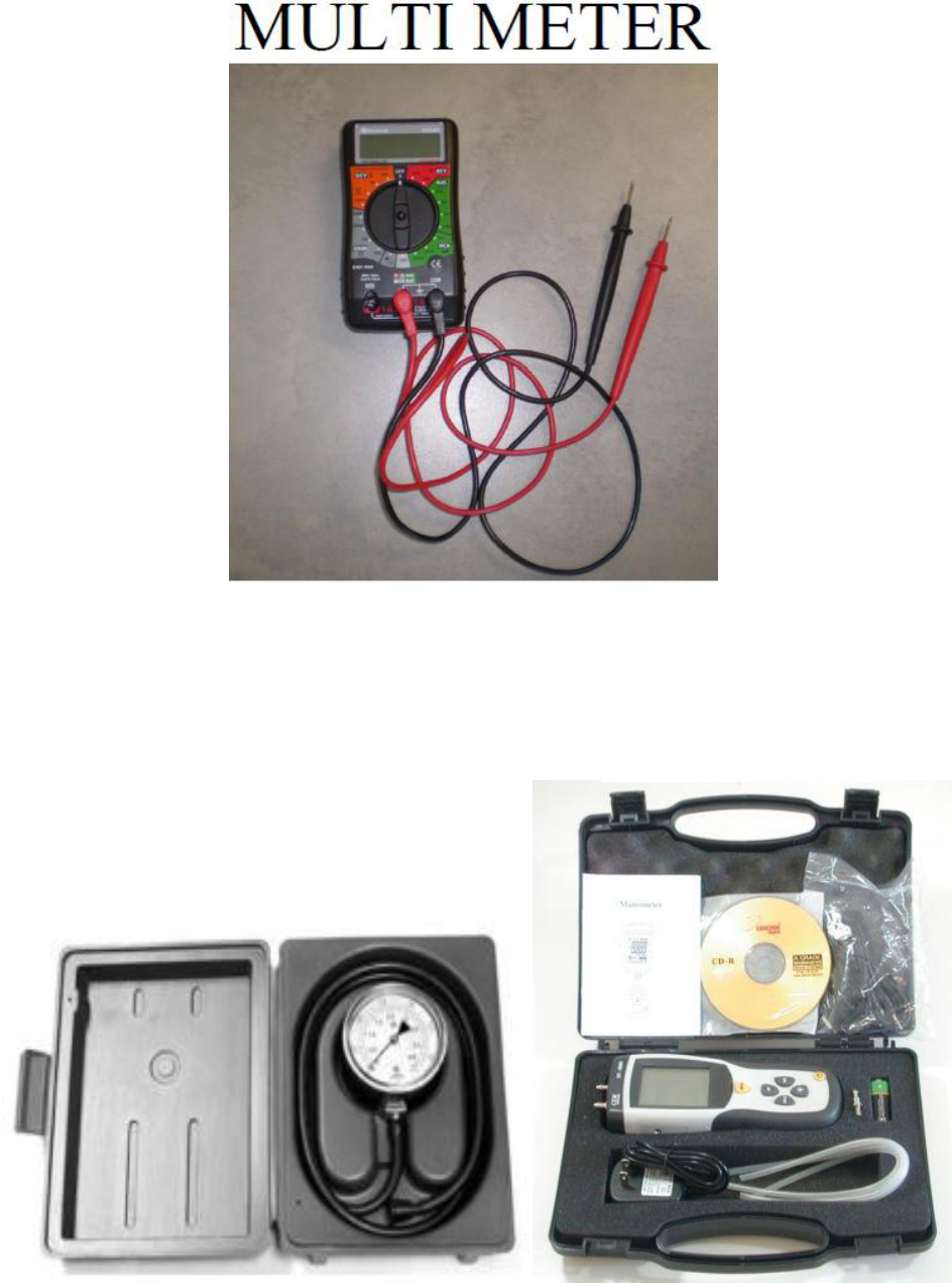
TOOLS NEEDED FOR TESTING
MANOMETER-LOW GAS FLOW PRESSURE GUAGE
DIGITAL STYLE GUAGE
SPRING STYLE GUAGE
3

4

DEXEN VALVE WIRING DIAGRAM
5

6

DEXEN VALVE ELECTRONIC IGNITION NOT SPARKING DIAGNOSTICS TEST
NOTE: BEFORE STARTING THIS TEST CONFIRM THAT ALL WIRE CONNECTIONS ARE GOOD
(A)
(B)
(A) (B) (C)
TEST #1 – Test for 2.8 to 3.4 AC volt power supply from either
the plug in transformer and/or the 2x D size battery backup
depending on what component is being used to power the
system.
STEP #1- If using the transformer, test that there is between 2.8
to 3.4 AC volts output (A).
If no, replace transformer.
If yes, got to TEST #2
TEST #2 – Confirm that the Battery Relay is sending the correct current to the ignition control module.
STEP #1-First remove the wire harness from the battery relay and test that there is between 2.8 to 3.4 AC volts on
the #1 & #3 pins on the battery relay using a multi meter set on 200AC volts (B).
If no, replace the battery relay.
If yes, go to STEP #2.
STEP #2-Reconnect the wire harness to the battery relay and test the ends of the 2 blue wires on the harness
assembly. You should get between 2.8 to 3.4 AC volts (C).
If no, replace wire harness.
If yes, go to TEST #3.
STEP #2- If using the battery backup, ensure that the batteries are producing
1.5 volts each.
Test that there is between 2.8 to 3.4 AC volts output from the battery pack
wires (B).
If no, replace battery pack housing.
If yes, go to TEST #2
7

DEXEN VALVE ELECTRONIC IGNITION NOT SPARKING DIAGNOSTICS TEST - continued
(A) (B) (C)
TEST #3 – Confirm that the wire harness connection on ignition
control module is correct (see picture).
STEP #1-Connect the 2 brown wires marked “SWI” together to
confirm pilot is sparking.
If yes, check the connections between Brown SWI wires from the
wire harness and the switch, remote or thermostat, including the
wiring used to connect between them.
If no, go to TEST #4.
TEST #4 – Confirm that the ignition control module and the spark electrode are functioning.
STEP #1-Remove wire harness off the ignition control module (A).
STEP #2-Use a jumper wire and jump pins #3 and #4 on the ignition control module (B).
If the pilot assembly starts sparking, replace wire harness.
If no, go to STEP #3.
STEP #3-Repeat the same test, but you will also have remove the igniter wire off the tab on the ignition control module
and hold the igniter wire 1/8” away from the igniter tab to check for spark (C).
If no, replace ignition control module.
If yes, go to STEP #4.
STEP #4-Check that the gap between the ceramic electrode and the pilot hood is 1/8
th
inch.
If no, adjust the electrode to have the 1/8
th
inch gap to the pilot hood.
If yes, the ceramic electrode is cracked and the pilot assembly needs replacing.
8

DEXEN VALVE ELECTRONIC IGNITION PILOT NOT LIGHTING DIAGNOSTICS TEST
(A)
(B)
(C)
(D) (E)
TEST #5 – Confirm continuity and current flow from the ignition control to the
gas valve.
STEP #1-Set your multi meter to 10A and plug the red probe into the 10A unfused
connection. Place the tip of the BLACK meter lead on the TPTH tab onto the gas
valve terminal block. Place the tip of the RED lead onto the tab on the end of the
orange wire of the ignition control wire harness (A). Active the unit to start
ignition. Once the pilot starts sparking you should be reading a cycling amperage
between 0.03 to 0.07.
NOTE: Once the pilot is operational it will have a current flow of 0.02 amps.
If “YES, go to TEST #6.
If “NO”, go to STEP #2.
STEP #2 – Set your multi meter for continuity. Remove the wire harness from the
control module and remove the orange wire from the valve. Put 1 meter lead on
the connector at the end of the orange wire and place the other meter lead on the
metal connector that the two orange wires are plugged into on the wire harness
pin connector (B).
If no, replace wire harness.
If yes, go to STEP #3.
STEP #3 – Remove wire harness from battery relay and place one meter lead to
on the metal connector that the orange wire is attached to on the small pin
assembly and place the other meter lead on the metal connector that the two
orange wires are attached to on the large pin assembly (C).
If no continuity, replace wire harness.
If yes go to STEP #4
STEP #4 – Set your multi meter to 10A and plug the red probe into the 10A
unfused connection. . Place the tip of the BLACK meter lead onto the end of the
black TP wire from the ignition control wire harness. Place the tip of the RED lead
onto the TP tab on the terminal block of the gas valve (D & E). You should be
reading 0.04 Amps.
If “YES, go to TEST #6.
If “NO”, go to STEP #5.
9

DEXEN VALVE ELECTRONIC IGNITION PILOT NOT LIGHTING DIAGNOSTICS TEST – continued
TEST #7 – Set your multi meter to 200 OHMS and place
the tip of the red meter lead on or in the connector at the
end of the pilot coil wire (as shown in the picture). Place
the tip of the black meter lead to the body of the valve (as
shown in the picture). You should be getting between 37
to 40 OHMS.
If no, replace gas valve.
If yes, check inlet pressure test port for gas flow to Valve
(see “Testing & Adjustments Section”).
If there is gas flow, check for blockage in pilot orifice, pilot
tube, and pilot connection port on valve. Remove
blockage where found.
If no gas to valve, inspect supply lines and shut off valves.
STEP #6 - Set your multi meter for continuity. Remove
the wire harness from the control module and remove
the black (TP) wire from the valve. Put 1 meter lead on
the connector at the end of the black wire and place the
other meter lead on the metal connector that the black
wire is plugged into on the wire harness pin connector.
If no, replace wire harness.
If yes, go to TEST #6.
10

11

DEXEN VALVE ELECTRONIC IGNITION BURNER NOT LIGHTING DIAGNOSTICS TEST
NOTE: BEFORE STARTING THIS TEST CONFIRM THAT ALL WIRE CONNECTIONS ARE GOOD
(A)
(B)
(C)
(D)
TEST #1 – Confirm continuity thru both GREEN wires from the Battery Relay
to the Ignition control wire harness, and from the Ignition control to the gas
valve pilot coil (A).
STEP #1 – Place the BLACK probe lead into where the green wires come out
of the wire harness connection, and place the RED probe lead into the end of
the green (TH) wire tab connection.
If “YES” go to STEP #2
If “NO”, replace wire harness.
STEP #2 – place the BLACK probe lead into where the green wire is connected
in the plug connection at the Battery Relay. Place the RED probe lead into
where the double green wires are connected in the plug connection for the
Ignition module (B).
If “YES”, go to TEST #2.
If “NO”, replace the wire harness.
TEST #2 – Confirm current thru green (TH) wire to the (TH) tab on the gas
valve.
NOTE: Pilot light must be running in order to perform this test.
STEP #1 – Place your RED meter lead probe onto the end of the green (TH)
wire from wire harness. Place your BLACK meter lead probe onto the (TH) tab
of the gas valve. You should be getting between .03 Amps (C).
If “YES”, go to Test #3.
If “NO”, replace ignition module.
NOTE – Confirm correct pressure to and out of gas valve.
STEP #1 – Check inlet pressure (IN) should be 7”wc for natural gas and 11”wc
to 13”wc for propane.
If “NO”, check supply lines and meter (NG)/regulator (LP)
If “YES”, Go to STEP #2.
STEP #2 – Check outlet pressure (OUT) should be 3.5”wc on high for natural
gas and 10”wc for propane.
If “NO”, confirm if a conversion was done that it was done correctly. If it was
done correctly, then replace gas valve.
12

ACS-1 ANTI CONDENSATION SWITCH FOR DEXEN ELECTRONIC IGNITION TROUBLE SHOOTING
ACS-1 TO DEXEN VALVE WIRING DIAGRAM
13

TROUBLESHOOTING
Pilot will not
light
Wiring
Remove ASC-1 connections and reconnect the original fireplace wire
harness to their correct connections and test to see if the unit
operates normally.
If “YES” reconnect the ACS-1 and check all connections. Ensure that
both the BLACK & YELLOW power connections are secure and making
good contact to both the BLACK & YELLOW wire on the ignition
control wire harness and that there is between 2.8 to 3.4 AC volts
going thru them.
If “NO”, refer to Dexen valve trouble shooting pages
Check for any shorted or broken wires. Perform a continuity test on
all ACS-1 wires.
If “YES”, that a wire is broken where there is no continuity then
replace the ACS-1.
If “NO” disconnect the pilot ON/OFF switch from the 2 BROWN wires
and jumper the brown wires to see if the pilot lights.
If “YES”, replace switch.
If “NO”, replace the ACS-1.
Pilot lights,
but burner
will not light
Wiring
Check wire connections, if loose reconnect. If burner will not come on
disconnect the burner ON/OFF (switch, remote or thermostat), and
jumper the two yellow wires. If “YES” replace (switch, remote or
thermostat). If “NO”, replace the ACS-1.
14

PROFLAME – S.I.T. VALVE with STEPPER MOTOR ELECTRONIC SYSTEM
15

PROFLAME – S.I.T. VALVE with STEPPER MOTOR WIRING DIAGRAM
16

17

PROFLAME – S.I.T. VALVE with STEPPER MOTOR ELECTRONIC IGNITION NOT SPARKING DIAGNOSTICS TEST
NOTE: BEFORE STARTING THIS TEST CONFIRM THAT ALL WIRE CONNECTIONS ARE GOOD
(A)
(B)
(C)
(D)
(E) (F)
TEST #1- Test that there is power being supplied at the 2 main sources.
STEP #1-Confirm there is 110 AC volts at the plug in receptacle on the
fireplace. Confirm there is 6.0 to 7.0 DC volts being supplied from the fan
control module thru the pins that the thin RED and GREY wire on the
connecting wire harness to the remote receiver connect to (A).
If “YES”, go to STEP #2.
If “NO”, replace fan control module.
STEP #2-Check the other end of the wire harness to ensure that there is 6.0
to 7.0 volts going thru the thin RED and GREY wires (B).
If “YES”, go to STEP #4.
If “NO”, replace wire harness.
STEP #3-Confirm continuity of the thin Red and GREY wires on the Remote
receiver wire harness. See picture (C) and (D).
If “YES, confirm wire connections.
If “NO”, replace remote receiver wire harness.
STEP #4-Attach wire harness to remote receiver (double check that the wire
harness is plugged in securely at both ends), and test the thicker RED and
BLACK wire to ensure that you are getting 6.0 to 7.0 volts (E).
If “Yes”, go to TEST #2 on the next page.
If “NO”, go to STEP #5.
STEP #5 – Confirm the lower 2 left pin connections that match up to the
thicker red and black wire from the wire harness plug on the remote receiver
is showing between 6.0 to 7.0DC volts. Slide the receiver to the ON position
and test as shown in picture (F).
If “YES” go to TEST #2.
If “NO”, replace remote receiver.
18

PROFLAME – S.I.T. VALVE with STEPPER MOTOR ELECTRONIC IGNITION NOT SPARKING DIAGNOSTICS TEST – continued
(A)
(B)
(C)
(D)
(E) (F)
TEST #2- Confirm for proper connection at all wire connections
between the receiver and the ignition module. Confirm there is 6.0 to
7.0 DC volts power supply from the receiver at both test points as
shown in the pictures (A) & (B).
STEP #1- Insert RED positive test probe into the female connector and
touch the outside of the connector with the BLACK test probe (6.0 to
7.0 DC volts). See picture (A).
If “YES”, go to STEP #2
If “NO”, Confirm continuity for both the thicker RED and BLACK wire on the
remote receiver wire harness,(see picture (B) for red wire & picture (C)
for black wire.
If “YES” to both wires confirm wire harness connection to remote
receiver. Go to STEP #2
If “NO” to either wire. Replace wire harness
STEP #2-Reconnect both the male and female DC wire plugs. Insert
the RED positive test probe into the wire harness plug at the Red wire
location. Insert the BLACK negative test probe into the wire harness
plug at the BLACK wire connection (6.0 to 7.0 volts). See picture (D)
If “YES”, go to TEST #3
If “NO”, go to STEP #3.
STEP #3-Confirm continuity for both the thicker RED and BLACK wire on the
ignition control module wire harness. See picture (E) for red wire, and
picture (F) for black wire.
If “YES”, go to TEST #6
If “NO”, replace ignition control wire harness.
19

PROFLAME – S.I.T. wIth STEPPER MOTOR VALVE ELECTRONIC IGNITION NOT SPARKING DIAGNOSTICS TEST – continued
(A) (B)
TEST #3 –Confirm that the igniter wire and the grounding wire is securely connected to the ignition module and that
the grounding wire is secured to the fireplace. See Picture (A).
If “NO”, ensure good connection.
If “YES”, go to STEP #1.
STEP #1-Remove igniter wire and hold it about 1/8
th
inch off the igniter tab (see picture (B)), and activate the fireplace
to start ignition.
If “YES”, go to STEP #2.
If “NO”, replace ignition control module.
FOR LHD50, IR3N, XIR3N, IR3G & XIR4N ONLY
“For HD81 See following page for extended spark testing TEST #4”
STEP #2-Check that ceramic electrode and the pilot hood has a 1/8
th
inch gap between.
If “YES”, replace ceramic electrode.
If “NO”, adjust gap to 1/8
th
inch.
20

HD81 Extended Spark Testing.
(A)
(B)
TEST #5-Confirm spark is transferring through the bulkhead.
STEP #1- Ensure that the ¼” flag on the electrode lead is
attached to the ¼” bulkhead spade, and the 3/16” flag is on the
3/16” bulkhead spade.
If “NO”, ensure correct connection.
If “YES” go to STEP #2
STEP #2-Check for spark coming thru the bulkhead by removing
the igniter wire 1/4” flag off the bulkhead 1/4” spade and hold it
1/8
th
inch off the spade and active the pilot to light.
If “NO”, replace the bulkhead.
If “YES” go to STEP #3.
STEP #3-Check that ceramic electrode and the pilot hood has a
1/8
th
inch gap between them.
If “YES”, replace ceramic electrode.
If “NO”, adjust gap to 1/8
th
inch.
TEST #4 –Confirm spark to bulkhead from ignition wire.
STEP #1-Remove igniter wire (1/4” connector) from bulkhead and
hold it about 1/8
th
inch off the bulkhead igniter tab and activate the
fireplace to start ignition (A).
If “YES”, go to TEST #4.
If “NO”, test the igniter wire for continuity. Replace if not good.
If “YES”, go to STEP #2.
STEP #2-Check the ground wire for continuity and good grounding.
Replace if not good
21

PROFLAME - S.I.T. VALVE with STEPPER MOTOR ELECTRONIC IGNITION PILOT NOT LIGHTING DIAGNOSTICS TEST
(A)
(B)
(C)
TEST #7 – Confirm the current flow thru the ORANGE wire
from the ignition control module to the gas valve pilot coil.
STEP #1 – Set your multi meter to 20 DCA mA. Take the
BLACK probe lead connect it to the end of the orange wire
from the ignition control module. Take the RED probe lead
and hold it against the red pilot coil tab on the gas valve (B).
Activate the unit to start up. Once it starts sparking you should
be reading a cycling amperage of 1.50 DCAmA to 19+ DCAmA
NOTE: The standard running current after approximately 30
seconds to a minute of the pilot operating. You should be
getting between 1.5 to 2.0 DCA milliamps.
If “NO” – Replace the ignition control module.
If “YES” – go to TEST #8.
TEST #8 – Set your multi meter to 200 OHMS and place the
tip of the red meter lead on the red pilot coil tab on the gas
valve. Place the tip of the black meter lead to the body of the
valve (C). You should be getting between 345 to 349 OHMS.
If “NO”, replace gas valve.
If “YES”, check inlet pressure test port for gas flow to Valve
(see “Testing & Adjustments Section”).
If there is gas flow, check for blockage in pilot orifice, pilot
tube, and pilot connection port on valve. Remove blockage
where found.
If no gas to valve, inspect supply lines and shut off valves.
TEST #6 – Confirm continuity thru the ORANGE wire from
the Ignition control wire harness to the gas valve pilot coil (A).
STEP #1 – Place the RED probe lead into where the orange
wire come out of the wire harness connection, and place the
BLACK probe lead into the end of the orange wire tab
connection.
If “YES” go to STEP #7
If “NO”, replace wire harness.
22

23

PROFLAME – S.I.T. VALVE with STEPPER MOTOR ELECTRONIC IGNITION BURNER NOT LIGHTING DIAGNOSTICS TEST
NOTE: BEFORE STARTING THIS TEST CONFIRM THAT ALL WIRE CONNECTIONS ARE GOOD
(A)
(B)
(C)
(D)
TEST #3 – Set your multi meter to 200 OHMS and place the tip of the red meter
lead on the green burner operator coil tab on the gas valve. Place the tip of the black
meter lead to the body of the valve (C). You should be getting between 328 to 332
OHMS.
If “NO”, replace gas valve.
If “YES”, go to TEST # 4.
TEST #2 – Confirm the current flow thru the GREEN wire from the ignition control
module to the gas valve pilot coil.
STEP #1 – Set your multi meter to DCA mA. Take the BLACK probe lead and contact it
to the end of the green wire from ignition control module wire harness. Take the RED
probe lead and hold it against the green pilot coil tab on the gas valve (B). Activate the
unit to start up. It will take approximately 30 seconds to a minute for the current to
stabilize. You should be getting between 1.5 to 2.0 DCA milliamps.
If “NO” – Replace the ignition control module.
If “YES” – go to TEST #3.
TEST #1 – Confirm continuity thru the GREEN wire from the Ignition control wire
harness to the gas valve pilot coil (A).
NOTE: Pilot flame must be running in order to perform this test.
STEP #1 – Place the RED probe lead into where the green wire comes out of the wire
harness connection, and place the BLACK probe lead into the end of the green wire tab
connection.
If “YES” go to TEST #2
If “NO”, replace wire harness.
TEST #4 – Confirm correct pressure to and out of gas valve. (D)
STEP #1 – Check inlet pressure (IN) should be 7”wc for natural gas and 11”wc to
13”wc for propane.
If “NO”, check supply lines and meter (NG)/regulator (LP)
If “YES”, Go to STEP #2.
STEP #2 – Check outlet pressure (OUT) should be 3.5”wc on high for natural gas and
10”wc for propane.
If “NO”, confirm if a conversion was done that it was done correctly. If it was done
correctly, then replace gas valve.
If “YES”, check for blockage in burner orifice, and manifold tube. Remove blockage
where found.
24

S.I.T. MANUAL VALVE ELECTRONIC SYSTEM
25

S.I.T. MANUAL VALVE ELECTRONIC WIRING DIAGRAM
26

27

S.I.T. MANUAL VALVE ELECTRONIC IGNITION NOT SPARKING DIAGNOSTICS TEST
NOTE: BEFORE STARTING THIS TEST CONFIRM THAT ALL WIRE CONNECTIONS ARE GOOD
(A)
(B)
(C)
(D)
TEST #1 - Confirm that there is between 6.0 to 7.0DC volts
power supply from the receiver at both test points, and
confirm all wire harness connections
STEP #1-Insert RED positive test probe into the female
connector and touch the outside of the connector with the
BLACK test probe (6.0 to 7.0 DC volts). See picture (A).
If “NO”, replace transformer.
If “YES”, go to STEP #2.
STEP #2-Plug in the transformer and connect it to the wire
harness. Insert the RED positive test probe into the wire
harness plug at the Red wire location. Insert the BLACK test
probe into the wire harness plug at the BLACK wire
connection. You should get between 6.0 to 7.0DC volts. See
picture (B)
If “NO”, go to STEP #3.
If “YES”, go to TEST #2.
STEP #3-Confirm continuity for both the thicker RED and
BLACK wire on the ignition control module wire harness. See
picture (C) for red wire, and picture (D) for black wire.
If “YES”, confirm wire connections and go to TEST #2
If “NO”, replace ignition control wire harness.
NOTE: If using only the battery backup, check that you have
1.5 volts coming from each of the 4 AA batteries, and that you
have between 6.0 to 7.0DC volts out of the battery pack
connection.
28

S.I.T. MANUAL VALVE ELECTRONIC IGNITION NOT SPARKING DIAGNOSTICS TEST-continued
(A) (B)
TEST #2 –Confirm that the igniter wire and the grounding wire is securely connected to the ignition module and that
the grounding wire is secured to the fireplace. See Picture (A).
If “NO”, ensure good connection.
If “YES”, go to STEP #1.
STEP #1-Remove igniter wire and hold it about 1/8
th
inch off the igniter tab and activate the fireplace to start ignition
(B).
If “YES”, go to STEP #2.
If “NO”, replace ignition control module.
STEP #2-Check that ceramic electrode and the pilot hood has a 1/8
th
inch gap between.
If “YES”, replace ceramic electrode.
If “NO”, adjust gap to 1/8
th
inch.
29

S.I.T. MANUAL VALVE ELECTRONIC IGNITION PILOT NOT LIGHTING DIAGNOSTICS TEST
(A)
(B)
(C)
TEST #3 – Confirm continuity thru the ORANGE wire from the
Ignition control wire harness to the gas valve pilot coil.
STEP #1 – Place the RED probe lead into where the orange wire
come out of the wire harness connection, and place the BLACK
probe lead into the end of the orange wire tab connection (A).
If “YES” go to STEP #7
If “NO”, replace wire harness.
TEST #4 – Confirm the current flow thru the ORANGE wire from
the ignition control module to the gas valve pilot coil.
STEP #1 – Set your multi meter to 20 DCA mA. Take the BLACK
probe lead connect it to the end of the orange wire from the ignition
control module. Take the RED probe lead and hold it against the red
pilot coil tab on the gas valve (B).
Activate the unit to start up. Once it starts sparking you should be
reading a cycling amperage of 1.50 DCAmA to 19+ DCAmA
NOTE: The standard running current after approximately 30 seconds
to a minute of the pilot operating. You should be getting between
1.5 to 2.0 DCA milliamps.
If “NO” – Replace the ignition control module.
If “YES” – go to TEST #8.
TEST #5 – Set your multi meter to 200 OHMS and place the tip of
the red meter lead on the red pilot coil tab on the gas valve. Place
the tip of the black meter lead to the body of the valve (C). You
should be getting between 332 to 336 OHMS.
If “NO”, replace gas valve.
If “YES”, check inlet pressure test port for gas flow to Valve (see
“Testing & Adjustments Section”).
If there is gas flow, check for blockage in pilot orifice, pilot tube, and
pilot connection port on valve. Remove blockage where found.
If no gas to valve, inspect supply lines and shut off valves.
30

31

S.I.T. MANUAL VALVE ELECTRONIC IGNITION BURNER NOT LIGHTING DIAGNOSTICS TEST
NOTE: BEFORE STARTING THIS TEST CONFIRM THAT ALL WIRE CONNECTIONS ARE GOOD
(A)
(B)
(D)
(E)
TEST #3 – Set your multi meter to 200 OHMS and place the tip of the red meter
lead on the green burner operator coil tab on the gas valve. Place the tip of the
black meter lead to the body of the valve (D). You should be getting between 330 to
334 OHMS.
If “NO”, replace gas valve.
If “YES”, go to TEST #4.
TEST #2 – Confirm the current flow thru the GREEN wire from the ignition
control module to the gas valve burner coil.
NOTE: Pilot flame must be operational in order to perform this test
STEP #1 – Set your multi meter to DCA mA. Take the BLACK probe lead and
contact it to the end of the green wire from ignition control module wire harness.
Take the RED probe lead and hold it against the green pilot coil tab on the gas valve
(B).
Activate the unit to start up. It will take approximately 30 seconds to a minute for
the current to stabilize. You should be getting between 1.5 to 2.0 DCA milliamps.
If “NO” – Replace the ignition control module.
If “YES” – go to TEST #3.
TEST #1 – Confirm continuity thru the GREEN wire from the Ignition control wire
harness to the gas valve pilot coil (A).
STEP #1 – Place the RED probe lead into where the green wire comes out of the
wire harness connection, and place the BLACK probe lead into the end of the green
wire tab connection.
If “YES” go to TEST #2
If “NO”, replace wire harness.
TEST #4 – Confirm correct pressure to and out of gas valve.
STEP #1 – Check inlet pressure (IN) should be 7”wc for natural gas and 11”wc to
13”wc for propane.
If “NO”, check supply lines and meter (NG)/regulator (LP)
If “YES”, Go to STEP #2.
STEP #2 – Check outlet pressure (OUT) should be 3.5”wc on high for natural gas
and 10”wc for propane.
If “NO”, confirm if a conversion was done that it was done correctly. If it was done
correctly, then replace gas valve.
If “YES”, check for blockage in burner orifice, and manifold tube. Remove blockage
where found.
32
