
COPYRIGHT © 2020 – 2022 LBC BAKERY EQUIPMENT, INC. 1 REV 7-2022
MODELS LMO-E-P, LMO-E-S, LMO-G-P & LMO-G-S
MINI ROTATING RACK OVEN
INSTALLATION, OPERATION & MAINTENANCE MANUAL
GAS OVENS: POST IN A PROMINENT LOCATION, THE INSTRUCTIONS TO BE FOLLOWED IN THE
EVENT THE SMELL OF GAS IS DETECTED. THIS INFORMATION CAN BE OBTAINED FROM THE
LOCAL GAS SUPPLIER
RETAIN THIS MANUAL FOR FUTURE REFERENCE
LBC BAKERY EQUIPMENT, INC.
6026 31
ST
Ave NE
Tulalip, WA 98271, USA
Toll Free: 888-722-5686
Email: sales@lbcbakery.com
Website: www.lbcbakery.com

COPYRIGHT © 2020 – 2022 LBC BAKERY EQUIPMENT, INC. 2 REV 7-2022
READ FIRST T
THIS MANUAL MUST BE RETAINED FOR FUTURE REFERENCE. READ, UNDERSTAND AND FOLLOW THE
INSTRUCTIONS AND WARNINGS CONTAINED IN THIS MANUAL.
W A R N I N G
DO NOT STORE OR USE GASOLINE
OR OTHER FLAMMABLE VAPORS
AND LI
QUIDS IN THE VICINITY OF
THIS OR ANY OTHER APPLIANCE.
D A N G E R
W A R N I N G
IMPROPER INSTALLATION,
ADJUSTMENT, SERVICE OR
MAINTENANCE CAN CAUSE
PROPERTY DAMAGE, INJURY OR
DEATH. READ THE INSTALLATION,
OPERATING AND MAINTENANCE
INSTRUCTIONS THOROUGHLY
BEFORE INSTALLING OR SERVICING
THIS EQUIPMENT.
C A U T I O N
ALWAYS KEEP THE AREA NEAR
THE APPLIANCE FREE FROM
COMBUSTIBLE MATERIALS.
This LBC Rotisserie was manufactured to rigid standards. The appliance has been tested and is
listed by Intertek Testing Services (ETL Semko) and meets applicable safety and sanitation
standards.
A) The responsibility of the manufacturer is to supply suitable, comprehensive instructions and
recommendations for proper operation and maintenance.
B) All operations, maintenance and repair of this or any LBC Bakery Equipment appliance must be
performed by properly trained and qualified personnel, and all such operations, maintenance
and repair must be performed in a diligent manner. It is the responsibility of the
owner/operator to ensure proper training and diligence of any person coming into contact with
either the subject units or the output (product, fumes or otherwise) of the subject units. It is the
responsibility of the owner/operator to ensure that the subject units are installed and operated
in accordance with OSHA Standard 1910.263.
C) A regular periodic program of cleaning, inspection and maintenance must be established, and
comprehensive maintenance records maintained. It is the sole responsibility of the
owner/operator to establish, schedule and enforce the frequency and scope of these programs
in keeping with recommended practice and with due consideration given to actual operating
conditions.
D) The appliance must be operated within limits which will not exceed its working limits. It is the
responsibility of the user to operate this appliance in accordance with the rules and limits
described in this manual and the published product specification sheet, and in accordance with
the directions and instructions of the owner/operator of the appliance or employer, and in
accordance with applicable federal, state and local laws and ordinances.

COPYRIGHT © 2020 – 2022 LBC BAKERY EQUIPMENT, INC. 3 REV 7-2022
TABLE of CONTENTS .
Read First . . . . . . . . . . . . . . . . . . . . . . . . . . . . . . . . . . . . . . . . . . . . . . . . . . . . . . . . . . . . . . . . . . . . . . . 2
Lighting and Shutdown – Gas Ovens . . . . . . . . . . . . . . . . . . . . . . . . . . . . . . . . . . . . . . . . . . . . . . . . . 4
Conditions of Installation . . . . . . . . . . . . . . . . . . . . . . . . . . . . . . . . . . . . . . . . . . . . . . . . . . . . . . . . . . 5
Dimensions and Utility Connections . . . . . . . . . . . . . . . . . . . . . . . . . . . . . . . . . . . . . . . . . . . . . . . . . 7
Installation . . . . . . . . . . . . . . . . . . . . . . . . . . . . . . . . . . . . . . . . . . . . . . . . . . . . . . . . . . . . . . . . . . . . . . 8
Startup Procedure and Check List . . . . . . . . . . . . . . . . . . . . . . . . . . . . . . . . . . . . . . . . . . . . . . . . . . 13
Using the Control . . . . . . . . . . . . . . . . . . . . . . . . . . . . . . . . . . . . . . . . . . . . . . . . . . . . . . . . . . . . . . . 16
Schematics . . . . . . . . . . . . . . . . . . . . . . . . . . . . . . . . . . . . . . . . . . . . . . . . . . . . . . . . . . . . . . . . . . . . 20
Illustrated Parts List . . . . . . . . . . . . . . . . . . . . . . . . . . . . . . . . . . . . . . . . . . . . . . . . . . . . . . . . . . . . . 24
Notes . . . . . . . . . . . . . . . . . . . . . . . . . . . . . . . . . . . . . . . . . . . . . . . . . . . . . . . . . . . . . . . . . . . . . . . . . 32
Warranty . . . . . . . . . . . . . . . . . . . . . . . . . . . . . . . . . . . . . . . . . . . . . . . . . . . . . . . . . . . . . . . . . . . . . . 33

COPYRIGHT © 2020 – 2022 LBC BAKERY EQUIPMENT, INC. 4 REV 7-2022
LIGHTING and SHUTDOWN – GAS OVENS .
Lighting Instructions
Daily use
1. Press the “Power” button to turn the oven on. Close the oven door.
2. Set the oven temperature to the desired operating temperature by pressing the up or down
arrow buttons next to the “Set Temperature” display.
After Long-term shut-down
1. Turn on the gas supply to the oven.
2. Lift the gas valve access door located below the control panel. Switch the gas valve “ON.”
Shut-Down Instructions
Daily Use
1. Press the “Power” button to turn the oven off.
Long-term shut-down
1. Lift the gas valve access door located below the control panel and switch the gas valve to
“OFF” position.
2. Turn off the gas supply to the oven.

COPYRIGHT © 2020 – 2022 LBC BAKERY EQUIPMENT, INC. 5 REV 7-2022
CONDITIONS of INSTALLATION (Part 1 of 2))
.
LBC Bakery Equipment shall, for a fee contingent on site location and provided the conditions of
installation are met, provide a factory-authorized service agency to install the LBC Rotisserie. The job
site must be ready for the installation before LBC Bakery Equipment or its authorized agent arrives. If
the installation site is not properly prepared or if there are construction delays, the customer shall be
responsible for all expenses incurred during this delay. All expenses resulting from job delay or
extension, for reasons beyond the control of LBC Bakery Equipment, shall be the responsibility of the
customer. Installation shall be conducted during normal business hours. This installation is for a single
trip. Start-up and training are not included.
IN ALL CASES, THE ELECTRICAL, WATER AND DRAIN CONNECTIONS AND VENTILATION MUST MEET
ALL FEDERAL, STATE AND LOCAL CODES OR ORDINANCES.
It is the responsibility of the owner/operator to do the following:
A. Secure all required permits and meet all local code requirements.
B. Ensure the installation site is cleared and ready for installation before the authorized installer arrives
on site. The site shall be smooth and level.
C. Provide electrical utilities within five (5) feet of the installation location per the specifications
provided by LBC Bakery Equipment
D. Provide licensed trades person to make the final electrical and water connections.
E. Provide adequate ventilation, including vented hoods and associated roof penetrations.
F. Remove all packing materials, crates, etc. resulting from the installation.
G. Provide any sheet metal work required by local codes or otherwise to bridge gaps between
appliance and adjacent walls or other building structures.
Inspection and Uncrating
Upon receipt of shipments, all packages should be inspected, and all visible or concealed damages noted
and signed for on the bill of lading. Any other damages should be reported to the carrier within 10 days.
Freight damages are the responsibility of the consignee.
All orders for replacement products resulting in freight damages will be processed under LBC’s standard
terms. Any reimbursement or credit is the responsibility of the freight carrier.
Carefully unpack the oven and place it in a work area as near to the final installation position as possible.
Installation of this equipment must be performed by an authorized service
representative. Prior to installation verify that all electrical and gas supplies
coincide with the manufacturers data label located on the right side below the
service panel.

COPYRIGHT © 2020 – 2022 LBC BAKERY EQUIPMENT, INC. 6 REV 7-2022
CONDITIONS of INSTALLATION (Part 2 of 2) )
The LMO oven ships with the following items please inspect your shipment to ensure that these
items were included.
• LMO Oven Rack
• Decorative hood front, sides and back pieces
If moving the oven through a 36” door opening it will be necessary to remove the oven door, door
latch, door hinges decorative valance and the rear panel.
Location
This appliance is not intended for outdoor use. This appliance is not intended for residential use.
This appliance is intended for commercial use in locations suitable for use as listed in this manual.
Clearances to combustible and non-combustible construction: 0” from back, sides and top.
This appliance is suitable for installation on combustible floors.
Installation Codes
For US Installation: The LMO oven must be installed in accordance with all State and local codes as
well as the National Electrical Code, ANSI/NFPA-70 (latest edition). Gas ovens must be installed in
accordance with the National Fuel Gas Code, ANSI-Z223-1/NFPA 54 (latest edition).
For Canadian installation: The LMO oven must be installed in accordance with all local codes. Gas
ovens must be installed in accordance with the CAN/CGA-B149.1 National Gas Installation Code
Gas Ovens: The appliance and its individual shutoff valve must be disconnected form the gas supply
piping system during any pressure testing of that system at pressures in excess of ½ psi.
Gas Ovens: The appliance must be isolated from gas supply piping system by closing its individual
manual shutoff valve during any pressure testing of the gas supply piping system at test pressures
equal to or less than ½ psi.
Model Number Coding
Electric Oven Number Format: LMO-EX-Y-Z, where X = rack size (use 6 for 6-pan rack, 8 for 8-pan
rack), Y = voltage (use -208 for 208V, -240 for 240V and -480 for 480V) and Z = base (use -S for stand,
-P for proofer base). Example: LMO-E8-480-P is a 480V electric oven with an 8-pan rack and proofer
base.
Gas Oven Number Format: LMO-GX-Y-Z, where X = rack size (use 6 for 6-pan rack, 8 for 8-pan rack),
Y = gas type (use -N for natural gas, -LP for propane gas) and Z denotes the base (use -S for stand, -
P for proofer base). Example: LMO-G6-N-S is a natural gas oven with a 6-pan rack and stand.

COPYRIGHT © 2020 – 2022 LBC BAKERY EQUIPMENT, INC. 7 REV 7-2022
DIMENSIONS and UTILITY CONNECTIONS .
-
COPYRIGHT © 2020 – 2022 LBC BAKERY EQUIPMENT, INC. 8 REV 7-2022
INSTALLATION (Part 1 of 6) .
Installing Casters
If your LMO oven is mounted on a stand, install casters using the supplied fasteners. With the oven still
on the shipping pallet, slide forward and install the two front locking casters. Move the oven with stand
forward again onto a pallet truck. Lift the oven with stand from the pallet and install the two rear casters.
Lift the oven only at the lift points shown in illustration.
Oven Location
See the Dimensions and Utility Connections section of this manual for oven dimensions. Select a location
with a smooth level surface and with adequate room to operate the appliance. If the oven mounting
surface is not level, loosen the caster bolts and shim with washers above the caster plates until the oven
is level. Re-tighten the caster bolts.
Gas Ovens: Gas Supply Connections
Verify that the gas type supplied to the oven matches the gas type listed on the oven’s data label. The
gas supply line must be at least the equivalent of 3/4” iron pipe. Ensure the pipes are free and clear of
any dirt or obstruction. Corrugated lines must not be used.
Codes require installation of a gas shutoff valve in the gas line ahead of the oven.
WARNING:
All gas ovens must be mounted on a stand or proofer base.
DO NOT mount directly to a solid surface as the combustion
air intake is from the bottom side of the oven.
Lifting Points. Use adequate
material handling equipment to lift
the oven into place. NOTE: Oven
weight is 1100 lbs.
WARNING:
Install oven on a surface adequate to support the
weight of the appliance.

COPYRIGHT © 2020 – 2022 LBC BAKERY EQUIPMENT, INC. 9 REV 7-2022
INSTALLATION (Part 2 of 6) .
See the Dimensions and Utility Connections section of this manual for gas connect point location.
Connect the gas supply line to the 3/4” NPT gas connection located at the rear of the oven. If the oven
is supplied with a flexible gas line, secure it to the oven and wall per the manufacturer’s specifications.
Use only connectors that comply with the Standard for Connectors for Movable Gas Appliances, ANZI
Z21.69 or Connectors for Movable Gas Appliances, CAN/CGA-6.16 with quick-disconnect devices that
comply with the Standard for Quick-Disconnect Devices for Use with Gas Fuel, ANZI Z21.41 or Quick
Disconnect Devices for Use with Gas Fuel, CAN 1-6.9.
Check the incoming gas pressure before the gas valve. Pressure must remain between 5 to 14 inch W.C.
for natural gas and 11 to 14 inch W.C. for propane gas - both with and without the burner firing.
Gas Ovens: Gas Type Conversion
1. Shut off the gas supply to the oven. Remove the bottom burner cover and the side access cover.
2. Disconnect the gas line at the top of the gas valve. Remove the four extended nuts at the bottom of
the burner assembly. Lower the burner out of the oven.
3. Remove the 15 orifice marked “65”. Use gas-approved Teflon tape to seal the orifices.
4. Replace the burner. Reconnect the gas line and replace the covers.
5. Check for leaks.
6. Operate the burner. Adjust the gas manifold pressure to 5” W.C. Supply pressure must remain
between 11 to 14 inch W.C. for propane gas - both with and without the burner firing.
7. Apply proper labeling to indicate (a) the correct gas type and (b) the pressure requirements on the
data plate and at the gas connection point.
Electrical Connections
WARNING:
Gas supply connections and any pipe joint compound must
be resistant to the action of natural and propane gases.
WARNING:
This appliance, when installed, must be electrically
grounded in accordance with local codes, or in the
absence of local codes, with National Electrical Code,
ANSI/NFPA 70 or the Canadian Electrical Code, CSA C22.2,
as applicable.
WARNING:
Gas Ovens: Do not connect oven to electrical supply
until after gas connections have been made.

COPYRIGHT © 2020 – 2022 LBC BAKERY EQUIPMENT, INC. 10 REV 7-2022
INSTALLATION (Part 3 of 6) .
See the Dimensions and Utility Connections section of this manual for oven electric connect-point
locations. Power can be connected at the electrical knockout holes in the oven. A flexible conduit or
cord is required. Provide sufficient length to allow the oven to be moved for cleaning without applying
tension to the connections.
Electric Ovens: Ensure that electrical supply matches voltage listed on the ovens data label. All electric
models require a 110/120V, 60Hz, 20A power supply as well as one of the following electrical supplies.
Volts Phase kW
Amps
MCA MOP
L1
L2
L3
208
3
12.5
39
26
39
50
60
240
3
12.5
30
30
30
40
50
480
3
12.5
15
15
15
20
30
Route electrical supply through knockout at rear of oven. Connect supply high voltage to terminal block
located within electrical control compartment at right rear side of oven and low voltage (120VAC) to
the black and white wires as shown.
Gas Ovens: All gas models are provided with a 6 ft power supply cord. The oven requires a dedicated
110/120V, 60Hz, 20A single phase power supply with ground. Note: The Commonwealth of
Massachusetts requires that gas flow must be prohibited when exhaust hood is not operational. If
installing oven in Massachusetts, or where a hood interface is required, remove the jumper wire from
the two-pole terminal block and connect the two wires from the hood sensing switch there.

COPYRIGHT © 2020 – 2022 LBC BAKERY EQUIPMENT, INC. 11 REV 7-2022
INSTALLATION (Part 4 of 6) .
Venting
Ventilation requirements vary with each installation and must comply with applicable portions of the
National Fire Protection Association Standard 96 as well as all State and local codes.
Install the exhaust fan interlock. A connection point (5A max) is provided for indirect venting (standard
exhaust hood). Connect point is located in the electrical connection box at right rear side of oven.
Consult local codes for vent interlock requirements.
Indirect venting (standard exhaust hood): Position the oven under the hood with adequate overhangs
and exhaust rates to completely capture the byproducts of combustion discharged from the flue. See
illustration below. From the termination of the flue to the filters of the hood venting system a clearance
of 18” must be maintained. The exhaust hood fan can be directly interlocked to the oven. Refer to the
Wiring Diagrams of this manual for terminal location.
COPYRIGHT © 2020 – 2022 LBC BAKERY EQUIPMENT, INC. 12 REV 7-2022
INSTALLATION (Part 5 of 6) .
Water Connections
See Dimensions and Utility Connections section of this manual for water connect point location. Oven
water supply should have a hardness of 4-6 grains per gallon, a pH of 6.5-8.0 and chlorides of less than
30 ppm. Water conditions outside of these parameters may void the warranty. Consult your local water
company and or water condition dealer before connecting water supply to oven.
Connect cold water supply to 1/2” NPT fitting located at rear of the oven. Use a 6 ft or longer flexible
water line.
If your oven is used with a proofer insert, it is recommended that a separate water line is provided.
Drain Connections
See Dimensions and Utility Connections section of this manual for drain connect point location. Connect
a 1/2” drain line to 1/2” NPT drain connector located at rear of oven. Route drain line to floor drain
allowing a minimum 1” air gap between drain line outlet and floor drain.
If your oven is used with a proofer insert, it is recommended that a separate drain line is provided.
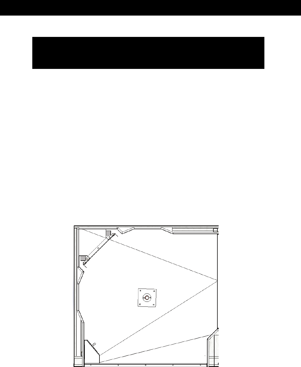
Shutter Settings
Top View of Oven Interior
WARNING:
Plumbing connections must comply with applicable Sanitary, Safety and
Plumbing Codes.
Rear shutter
Middle shutter
Front shutter

COPYRIGHT © 2020 – 2022 LBC BAKERY EQUIPMENT, INC. 13 REV 7-2022
INSTALLATION (Part 6 of 6) .
Position
Front Shutter
Middle Shutter
Rear Shutter
inch
mm
Fraction
inch
mm
Fraction
inch
mm
Fraction
1 (top)
0.32
8
5/16
0.25
6
1/4
0.38
10
3/8
2
0.18
5
3/16
0.29
7
9/32
0.38
10
3/8
3
0.15
4
5/32
0.18
5
3/16
0.32
8
5/16
4
0.15
4
5/32
0.21
5
3/16
0.32
8
5/16
5
0.18
5
3/16
0.21
5
3/16
0.29
7
9/32
6 (bottom)
0.25
6
1/4
0.41
10
13/32
0.41
10
13/32
Shutter Settings
Appliance Restraint
Adequate means must be provided to limit the movement of the appliance.
STARTUP PROCEDURE and CHECK LIST (Part 1 of 3) .
LMO START-UP FORM: This form MUST BE SIGNED & RETURNED to LBC via Email to
[email protected]om or FAX 425-642-8310, in order for the Customers Warranty to
take effect.
**REQUIRED TOOLS/METER: manometer, multi-meter, amp clamp, combustion
meter/gas analyzer, 6' ladder, variety of standard & metric hand tools (including
allen wrenches)
LMO Oven Inspection Procedure
Specifics
Serial Number
________________________________________
Model Number
________________________________________
Location Name
________________________________________
Address
________________________________________
City, State
________________________________________
Photos:
(Attach the following Photos to this inspection):
Any visible
damage
_____________
Data plate
_____________
Power Connection in the oven connection box
_____________
Water Supply (filter, RO system or softener)
_____________
Gas Supply
Pipe
_____________
Location Details:
AS FOUND
If No,
CORRECTED?
Oven on Non-combustible floor?
Y_____
N_____
_____
Is the oven
Level?
Y_____
N_____
_____

COPYRIGHT © 2020 – 2022 LBC BAKERY EQUIPMENT, INC. 14 REV 7-2022
STARTUP PROCEDURE and CHECK LIST (Part 2 of 3) .
Oven Type:
Gas Nat____ Prop.___
Electric (Voltage) 208 Volts______ 240 Volts______ 480 Volts ________
Install Quality:
Supply voltages: Dedicated 120 VAC, 15Amp Max Rating
Y_____
N_____
_____
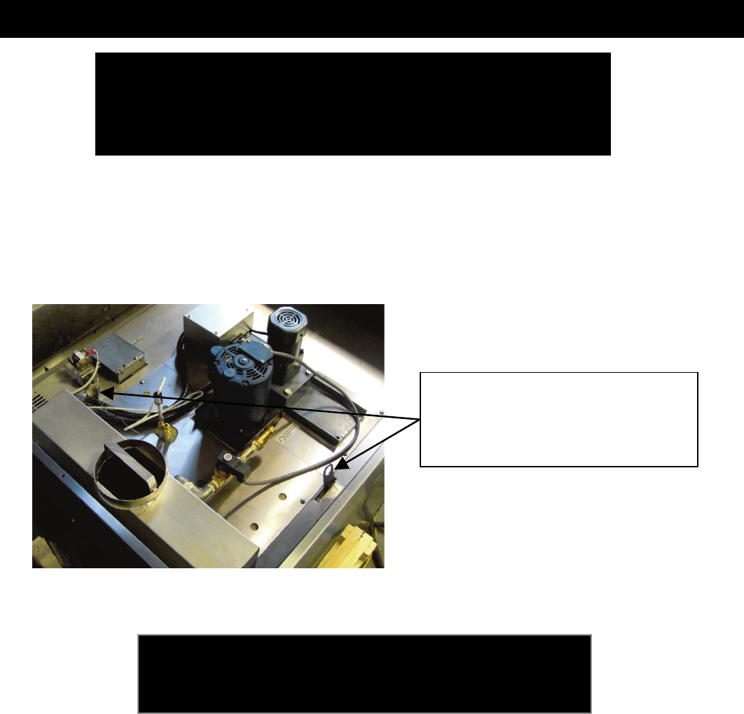
Water Connection: No leaks? (Fig. 1)
Y_____
N_____
_____
Gas Connection: No leaks? (Fig. 2)
Y_____
N_____
_____
Drain Connection: Properly connected and
to an air-gap drain? (Fig. 3)
Y_____
N_____
_____
If hood interlock is required; confirm proper connection and
hood power switch is properly labeled
Y_____
N_____
_____
Functional Check: Turn on power to oven.
Press power button on control. Unit turns on?
Y_____
N_____
_____
Interior lights turn on when the door is opened?
Y_____
N_____
_____
Blower motor rotation: Counter-Clockwise when viewed
from top? (Should be CCW)
Y_____
N_____
_____
Rack starts to rotate smoothly?
Y_____
N_____
_____
Burner test:
Set to 125° F. (Temp starts to rise within a
minute?):
Y_____
N_____
_____
(If temp does not start to rise, Call
LBC)
Supply side gas pressure when burner is running?
_____
WC
_____
(If less than 5" and greater than 14", Call LBC)
Set to 300° F. Minutes to go from 150° to 250° F?
_____
Mins
Combustion Test:
Set to 350° F. Wait one minute:
Check Carbon Monoxide for 1 minute.
CO__________PPM
(If greater than 75 PPM, Call LBC)
Take Photo of CO Measurement.
Check sensor VOLTAGE at test point:
____________VAC
(If Voltage is not between 3-6 VDC, call LBC)
Steam Test - Confirm oven temp is at 350°F. Can you hear
the solenoid open and water spraying? Any visible steam?
Y_____
N_____
_____
Rack Stopping Position (Hot Oven):
Carrier Stops at the door when door is opened?
Y_____
N_____
_____
Check Air-Gap settings on pressure panel.
Refer to settings in manual.
Y_____
N_____
_____

COPYRIGHT © 2020 – 2022 LBC BAKERY EQUIPMENT, INC. 15 REV 7-2022
STARTUP PROCEDURE and CHECK LIST (Part 3 of 3) .
Final Inspection:
Loading doors open/close freely past 90° without obstruction?
Y_____
N_____
_____
Doors open 1/2" to 1" before motor and rack Stops?
Y_____
N_____
_____
Gas is
on?
Y_____
N_____
_____
Electrical Is on?
Y_____
N_____
_____
Water is on?
Y_____
N_____
_____
Gaskets: Installed and seated correctly?
Y_____
N_____
_____
No cracks or missing pieces?
Y_____
N_____
_____
All screws and electrical are tight? (If not, tighten down firmly)
Y_____
N_____
_____
All plumbing connections are tight and do not leak.
Y_____
N_____
_____
Fig. 1
Fig. 2
Fig.3
FOR TECHNICAL SUPPORT, CALL LBC: 888-722-5686 x1
Name:
__________________________________________ Company:
_____________________________
Signature:
____________________________________________________
Date
____________________________________________________

COPYRIGHT © 2020 – 2022 LBC BAKERY EQUIPMENT, INC. 16 REV 7-2022
USING the CONTROL .
Digital Control (-70)
J
A
B
C
D
E
F
G
H
I
K

COPYRIGHT © 2020 – 2022 LBC BAKERY EQUIPMENT, INC. 17 REV 7-2022
Digital Control (-70)
Power On
When power to the oven is on and all circuit breakers are turned on, the green LED in the corner of
the “On/Off” button will be lit. To turn the oven on, press the “On/Off” button (A). The display will
light up and indicate that the control and the oven are on. If the oven door is closed, the oven will
begin to heat to the temperature indicated in the “Set Point” display.
To set the Temperature
Use the up and down buttons (B) next to the “Set Point” display to set the oven to the desired
temperature. This temperature can be adjusted at any time. The oven will heat or cool to this set
point. The actual temperature will fluctuate up and down about the set point as indicated in the
“Actual” temperature display. Note: Allow the oven to operate for one hour at the desired
temperature before you begin to bake.
To set the Bake Timer (Normally set in minutes)
Use the up and down buttons (C) next to the timer display to set the bake time. This timer indicates
the remaining time in the bake and can be adjusted at any time. The display will show the
remaining time in full minutes. An example of this is that if the time is set to 1 minute, it will show 1
minute as it counts down to zero seconds.
The time can also be set to less than one minute or up to 59 seconds. To choose seconds, press the
down button that is to the right of the time display until it reaches zero minutes. Continue to hold
the down button for an additional 5 seconds. The display will change to show a time of 01 with a
decimal point showing. This indicates one second. Press the up button to increase the time up to
59 seconds. Increase the time setting to greater than 59 seconds to return to full minute settings.
To set the Steam Timer
Use the up and down buttons (D) next to the steam timer display to set the steam time. Note that
the steam time is limited by preset parameters in the control. This timer indicates the remaining
time in the steam event. When the steam event is complete, the steam timer display will indicate
“—“.
To set the Blower Functions
The blower button (E) selects the way the circulation blower will operate during the bake. There are
three options: 1) “ON” will cause the blower to operate at all times while the oven is baking except
during the time that the steam timer is counting down. 2) “PULSE” will cause the blower to turn on
and off during the bake cycle to slow the baking process down. 3) “DELAY” will cause the blower to

COPYRIGHT © 2020 – 2022 LBC BAKERY EQUIPMENT, INC. 18 REV 7-2022
stay off for the first 90 seconds after the start button is pressed. Note that this function will be
locked out if the control is configured with the programming limitation feature turned on.
To set Vent Functions
The vent button (F) selects the way the vent will operate during the bake. There are three options:
1) “OPEN” will cause the vent to be open all times while the oven is baking except during the time
that the steam timer is counting down. 2) “AUTO” will cause the vent to open during the last third
of the bake cycle. 3) “CLOSED” will cause the vent to stay closed through the entire bake cycle.
Note that this function will be locked out if the control is configured with the programming
limitation feature turned on.
To start the Bake Timer
Press the “START/STOP” button (G) to start the bake after loading the oven with the rack of product. The
loading door must be closed for the bake timer to start. Once the start button is pressed, the steam time will
count down if the steam time is set. If the loading door is opened, the bake timer and steam timer will
pause. The timers will resume automatically when the door is closed.
End of Bake Alarm
When the time has run out, the time display will show two dash lines. The timer alarm will sound. You may
add time to the bake by pressing the up button (C) in the timer display. The timer will automatically resume.
You may also press the “START/STOP” button (G) to silence the alarm and then adjust the time. If you press
the “START/STOP” button (G) again, the displays will reset to the original bake time and steam time. You may
also open the door to silence the alarm and check the baking progress.
Selecting Preset Recipes
To select a preset recipe, press the left and right buttons next to the “SELECT PRESET” display (I). The preset
that is shown will be the recipe that will be operating when the “START/STOP” button (G) is pressed. Note: if
the control is configured for Step Recipe operation, the six buttons above the “SELECT PRESET” will indicate
the step that is being executed (see Step Recipe Operation for specific instructions).
Saving a Preset Recipe
A recipe may be saved as a preset recipe in the following manner. 1) Select the preset number (H) under
which you want to save the recipe. 2) Enter all of the settings. 3) press the “SAVE” button (J) twice. Note
that this function will be locked out if the control is configured with the Programming Limitation (PL) function
turned on. In order to save a recipe, the programming limitations feature must be turned off to save and can
then be turned on to prevent any changing the recipe.
Step Recipe Operation
The control can be configured to operate in Step mode. In step mode, the control creates six sequential
recipe steps and executes all six in order. The step mode is best utilized with preset recipes only.
Recipe Set-up in Step Mode
COPYRIGHT © 2020 – 2022 LBC BAKERY EQUIPMENT, INC. 19 REV 7-2022
When the step mode is turned on, the preset recipe is selected using the left and right buttons in the “SELECT
PRESET” display. The step is selected using the six numbered buttons above the “SELECT PRESET” display.
To save a recipe with Step Mode on
Select the recipe number you wish to program. Press step button 1 and enter the recipe parameters. Press
step button 2 and enter the recipe parameters. Repeat this through all the steps. Make sure that you set the
time to “00” in the steps you don’t want. Press the save button twice to save the recipe.
Note: When the oven is configured to operate in Step mode, all recipes must be programmed as steps, even
if you only want one step. Be sure that the remainder of the steps have “00” time.
To Change between Degrees F and Degrees C
The control can change from one temperature scale to the other. To change, simply press the button (K)
marked “F/C”. The oven can also be configured to lock in either degrees F or degrees C.

COPYRIGHT © 2020 – 2022 LBC BAKERY EQUIPMENT, INC. 20 REV 7-2022
SCHEMATICS (Part 1 of 4) .

COPYRIGHT © 2020 – 2022 LBC BAKERY EQUIPMENT, INC. 21 REV 7-2022
SCHEMATICS (Part 2 of 4) .

COPYRIGHT © 2020 – 2022 LBC BAKERY EQUIPMENT, INC. 22 REV 7-2022
SCHEMATICS – ELEC OVENS (Part 3 of 4) .

COPYRIGHT © 2020 – 2022 LBC BAKERY EQUIPMENT, INC. 23 REV 7-2022
SCHEMATICS – GAS OVENS (Part 4 of 4) .

COPYRIGHT © 2020 – 2022 LBC BAKERY EQUIPMENT, INC. 24 REV 7-2022
ILLUSTRATED PARTS LIST (Part 1 of 8) .

COPYRIGHT © 2020 – 2022 LBC BAKERY EQUIPMENT, INC. 25 REV 7-2022
ILLUSTRATED PARTS LIST (Part 2 of 8) .

COPYRIGHT © 2020 – 2022 LBC BAKERY EQUIPMENT, INC. 26 REV 7-2022
ILLUSTRATED PARTS LIST (Part 3 of 8) .
n
Item
No
Part No Description Qty
1
151-741
Door Assembly
2
2
151-499
Spacer Bushings
2
3
151-500
Door Mount
1
4
73000-10
Sprocket (35B, 13TG)
2
5
151-503
Bronze Bearing
4
6
151-744
Door Linkage Assembly
2
7
Chain Link
Chain and Master Link (35B)
2
8
151-745
Bottom Door Support
1
9
CR-34
Cam Follower
2
10
151-798
Door Switch Magnet Assembly
1
11
51001-17
Bottom Door Handle Spring
1
12
151-493
Silicone Lap Strip
2
13
151-518
Inner Door Latch
2
14
151-792
Door Handle Assembly
1
15
51001-16
Top Door Handle Spring
1
16
72602-24-5
Vertical Door Gasket
1
17
180-762-2
Reed Switch Assembly (Door sw.)
1
17

COPYRIGHT © 2020 – 2022 LBC BAKERY EQUIPMENT, INC. 27 REV 7-2022
ILLUSTRATED PARTS LIST (Part 4 of 8) .
Item
No
Part No Description Qty
1
73000-06a
Driven Gear
1
2
73000-05c
Motor Gear
1
3
30200
-56-1
Motor
Rotation Dr
1
4
70200-11
Bushing
1
5
151-739
Rotator Bottom
Assembly
1
6
150-150-2
Spacer, Rotator
4
7
151-740
Rotator Top
Assembly
1
8
50803-002
Drive Collar
1
9
70200-13
Bushing
1
10
70200-14
Friction Washer
1
11
20601-04
Snap Ring
1
12
151-482
Drive Shaft
1
13
30301-15
Roller Switch
1
14
20104-20
1/4-20 x 3/4” HH
Mach Screw, SS
4
15
20202-05
1/4 Split Lock
Washer, SS
4
16
20104-09
3/8-16 x 5/8” Mach
Cap Screw, SS
8
17
20202-09
3/8 Split Lock
Washer, SS
8
18
20105-20
3/8-16 x 1/2 Mach
Cup Screw, SS
1
19
20105-04
6mm-1mm x
10mm Set
Screw, SS
2
20
151-524
Spacer,
Roller Switch
1
21
151-523A
Rotator Cam
3
22
70200-12
Washer 1.55 ID
1
23
151-524-1
Rack Rotation Plate
1
24
40704-12
Rotation Capacitor
1
25
70200-15
Split Rulon Bushing
(Part not Shown)
1

COPYRIGHT © 2020 – 2022 LBC BAKERY EQUIPMENT, INC. 28 REV 7-2022
ILLUSTRATED PARTS LIST – GAS OVENS (Part 5 of 8) .
Item No
Part No
Description
Qty
1
30200-66
Circulation Motor, ½ HP, 115/208-230 VAC
1
2
71500-30
Impeller, Forward Curve
1
3
151-717
Blower Mount Weldment
1
4
151-268
Motor Mount, C-Face
1
5
151-271
Clamp, Blower Seal
1
6
151-270
Seal, Blower
1
8
151-272
Stiffeners, Blower Plate
2
11
151-273b
Blower Involute
1
12
151-211
Pipe, Temperature Sensor
1

COPYRIGHT © 2020 – 2022 LBC BAKERY EQUIPMENT, INC. 29 REV 7-2022
ILLUSTRATED PARTS LIST – GAS OVENS (Part 6 of 8) .
Item
No
Part No Description Qty
1
151-722
Exhaust Collector
1
2
151-727
Exhaust
Restrictor
1
3
151-719
Chimney
1
4
151-702b
Heat
Exchanger
1
5
151-160
Burner Box
1
6
151-311
Mount, Burner
- Left
1
7
151-312
Mount, Burner
- Right
1
8
151-313
End, Burner
Assembly
2
9
80400-01
Orifice*
15
10
150-215
Gas Pipe Assy
1
11
151-310
Manifold
1
12
70305-01
Elbow, 1/2NPT
- Steel
1
13
70305-09
Elbow, 3/4NPT
- Steel
1
14
70307-02
Reducer, Pipe
– 3/4 x 1/2 NPT,
Steel
1
15
70302-08
Nipple, Close
– 1/2NPT, Steel
1
16
80505-15
Gas Valve,
Combination
1
17
70302-09
Gas Connector
– 18”
1
18
80002-14
Burner, Inshot
15
19
41100-36-1
Flame Sensor
1
20
80302-12
Ignitor, Hot
Surface
1
21
151-763
Burner / Heat
Exchanger Assy
1
* Orifice Sizes:
Natural Gas @ 3.5 inwc =
3/64” (0.047)[1.19mm]
Propane Gas @ 5.0 inwc =
#65 (0.035)[0.89mm]
21 = Complete
Burner / Heat
Exchanger Assembly

COPYRIGHT © 2020 – 2022 LBC BAKERY EQUIPMENT, INC. 30 REV 7-2022
ILLUSTRATED PARTS LIST – ELECTRIC OVENS (Part 7 of 8)
Item No
Part No
Description
Qty
1
11091-02-1
Element Assy (4166W @240V)
4
1
11091-03-1
Element Assy (4166W @480V)
4
2
31200-08
Ground Lug, 2-Hole
1
3
30500-07
Term Block, 3-Pole
1
4
151-164b
Cover, Heat Exchanger
1
5
20202-01
Hex Bolt, 6mm-1x12mm, MS
8
6
30700-17
Contactor, 3-Pole, 40A, 24V Coil
1

COPYRIGHT © 2020 – 2022 LBC BAKERY EQUIPMENT, INC. 31 REV 7-2022
ILLUSTRATED PARTS LIST – ELECTRIC OVENS (Part 8 of8)

COPYRIGHT © 2020 – 2022 LBC BAKERY EQUIPMENT, INC. 32 REV 7-2022
NOTES .

COPYRIGHT © 2020 – 2022 LBC BAKERY EQUIPMENT, INC. 33 REV 7-2022
