
Juniper Mist Wired Assurance
Conguraon Guide
Published
2024-08-30

Juniper Networks, Inc.
1133 Innovaon Way
Sunnyvale, California 94089
USA
408-745-2000
www.juniper.net
Juniper Networks, the Juniper Networks logo, Juniper, and Junos are registered trademarks of Juniper Networks, Inc.
in the United States and other countries. All other trademarks, service marks, registered marks, or registered service
marks are the property of their respecve owners.
Juniper Networks assumes no responsibility for any inaccuracies in this document. Juniper Networks reserves the right
to change, modify, transfer, or otherwise revise this publicaon without noce.
Juniper Mist Wired Assurance Conguraon Guide
Copyright © 2024 Juniper Networks, Inc. All rights reserved.
The informaon in this document is current as of the date on the tle page.
YEAR 2000 NOTICE
Juniper Networks hardware and soware products are Year 2000 compliant. Junos OS has no known me-related
limitaons through the year 2038. However, the NTP applicaon is known to have some diculty in the year 2036.
END USER LICENSE AGREEMENT
The Juniper Networks product that is the subject of this technical documentaon consists of (or is intended for use
with) Juniper Networks soware. Use of such soware is subject to the terms and condions of the End User License
Agreement ("EULA") posted at hps://support.juniper.net/support/eula/. By downloading, installing or using such
soware, you agree to the terms and condions of that EULA.
ii

Table of Contents
About This Guide | vii
1
Get Started
Juniper Mist Wired Assurance Overview | 2
Hardware and Soware Requirements for Your Wired Network | 3
Switch Administrator Role Requirements | 3
Deploy Your Wired Network | 6
Explore Juniper Mist Features | 8
Port Proles Overview | 9
Group-Based Policy Conguraon Overview (Mist) | 14
2
Switch Conguraon
Switch Conguraon Overview (Mist) | 17
Onboard Switches to Mist Cloud | 18
Switch Onboarding Prerequisites | 18
Onboard a Greeneld Switch | 19
Onboard a Browneld Switch | 19
Congure Switches | 22
Create a Switch Conguraon Template | 23
Assign a Template to Sites | 24
Congure Switch-Specic Sengs | 24
Congure Switch-Specic Sengs Manually | 25
Congure Switch-Specic Sengs Using the Bulk Upload Opon | 25
Verify the Switch Conguraon | 27
Switch Conguraon Opons | 29
iii

QoS Conguraon | 65
Congure SNMP on Switches | 75
Congure SNMP at the Organizaon Level | 76
Congure SNMP at the Site Level | 78
Congure SNMP at the Device Level | 80
Congure DHCP Server or Relay on a Switch | 82
Prerequisites | 82
Congure DHCP Server | 82
Congure DHCP Relay | 89
Manage or Update Conguraon Sengs | 92
Manage Templates Sengs | 93
Update Switch Conguraon Sengs at the Site Level | 94
Add or Delete a CLI Conguraon | 94
Upgrade Junos OS Soware on Your Switch | 96
Free Up Storage Space on Your Switch | 96
Upgrade the Junos OS Soware on Your Switch | 99
Assign a Role to Switches | 103
Replace a Switch | 104
3
Switch Dashboards
Switch Metrics | 109
Switch Details | 110
Switch Ulies | 118
4
Virtual Chassis
Conguraon
Virtual Chassis Overview (Juniper Mist) | 121
Congure a Virtual Chassis Using EX2300, EX4650, or QFX5120 Switches | 125
iv

Congure a Virtual Chassis Using EX3400, EX4100, EX4100-F, EX4300, EX4400, or
EX4600 Switches | 129
Manage a Virtual Chassis Using Mist (Add, Delete, Replace, and Modify Members) | 134
Prerequisites | 135
Replace a Member Switch in a Virtual Chassis | 136
Replace a Non-FPC0 Member in a Virtual Chassis | 136
Replace the FPC0 Member in a Virtual Chassis | 140
Renumber the Virtual Chassis Members | 144
Reassign the Virtual Chassis Member Roles | 146
Delete Virtual Chassis Members | 148
Add a Member Switch to a Virtual Chassis | 149
5
Campus Fabric Conguraon
Which Campus Fabric Topology to Choose | 154
How to Migrate a Tradional Enterprise Network to a Juniper Campus Fabric | 162
Congure Campus Fabric EVPN Mulhoming | 167
Congure Campus Fabric Core-Distribuon | 175
Congure Campus Fabric IP Clos | 185
6
Wired Service Levels
Service Level Expectaons (SLE) | 196
Wired SLEs Dashboard | 205
Wired Throughput SLE | 207
Wired Successful Connect SLE | 209
Switch Health SLE | 210
Switch Bandwidth SLE | 212
7
Troubleshoong
Troubleshoot Your Switch | 216
v


About This Guide
Hey there! If you're looking to congure Juniper switches using the Mist portal, you've come to the right
place. The Mist portal oers essenal features for switch conguraon and management through the
Juniper Mist Assurance cloud service.
Just a heads up, if you want to congure switches through the portal, make sure you have a Mist Super
User role assigned to your account. Having this role will give you the necessary permissions and access
to perform switch conguraons within the portal. Happy conguring!
vii

1
CHAPTER
Get Started
Juniper Mist Wired Assurance Overview | 2
Hardware and Soware Requirements for Your Wired Network | 3
Switch Administrator Role Requirements | 3
Deploy Your Wired Network | 6
Explore Juniper Mist Features | 8
Port Proles Overview | 9
Group-Based Policy Conguraon Overview (Mist) | 14

Juniper Mist Wired Assurance Overview
Juniper Mist™ Wired Assurance is an AI-driven cloud service that brings some awesome benets, such
as cloud management and Mist AI, to enterprise campus switches. Wired Assurance simplies all aspects
of switch management that include device onboarding, conguraon at scale, and monitoring and
troubleshoong.
With Wired Assurance, you get real-me visibility into the health and performance of your wired
network. You can see how your switches are doing, check out service level expectaons (SLE) metrics,
and even get insights into the end user experiences.
For a quick overview of Wired Assurance, watch the following video:
Video: Mist Wired Assurance Overview
When it comes to switch conguraon, Wired Assurance lets you use conguraon templates to easily
apply consistent conguraons across all your sites and devices, providing a streamlined switch
management experience. Wired Assurance also has handy tools and features that help you troubleshoot
network issues easily.
Wired Assurance is available as a subscripon-based service right through the Juniper Mist portal.
Wired Assurance supports EX and QFX Series switches. We recommend using EX Series switches in
places where you need interoperability with Juniper Mist Access Points (APs). To nd out which
switches are supported by Juniper Mist Wired Assurance, refer to Juniper Mist Supported Hardware.
Watch the following video to understand how Wired Assurance can automate and simplify device
provisioning, deployment, and operaon.
Video: Wired Assurance - Day 0, Day 1, and Day 2+
RELATED DOCUMENTATION
Switch Conguraon Overview (Mist) | 17
2

Hardware and Soware Requirements for Your
Wired Network
SUMMARY
Read this topic to learn about the various hardware opons and get started installing and
onboarding your devices.
Juniper provides a wide range of hardware to support your wired networking needs. Juniper Mist Wired
Assurance supports onboarding, conguraon, and management of Juniper EX Series and QFX Series
switches. Click the links below to access datasheets, quick start guides, and hardware guides for these
switches on the Juniper Mist Supported Hardware page:
• EX Series Switches
• QFX Series Switches
NOTE: The informaon provided on the Juniper Mist Supported Hardware page is not specic to
Wired Assurance. This page lists all the devices that can be managed through the Mist portal.
For the Wired Assurance support, the minimum required Junos OS release (rmware image) for Juniper
switches across plaorms is 18.2R3. Be aware that 18.2R3 has reached end of support. We recommend
that you upgrade to a JTAC-suggested Junos release. For the suggested releases, refer to Junos
Soware Versions – Suggested Releases to Consider and Evaluate. If you have any quesons, write to
Switch Administrator Role Requirements
Before you onboard and congure your switches, ensure that you have the required switch
administrator role.
3

The following table lists the available privileges for each switch administrator role (Super User,
Network Admin, Help Desk, and Observer). A check mark next to a privilege means that the user
role enjoys that privilege. An x means that the user role does not enjoy that privilege.
Privileges Super User Network
Admin (All
Sites Access)
Network
Admin (Site
Group or
Specic Sites
Access)
Helpdesk Observer
Claim switches ✓ × × × ×
Adopt switches ✓ ✓ ✓ ✓ ✓
Release switches ✓ × × × ×
View switch details ✓ ✓ ✓ ✓ ✓
Access ulity tools
(ping, traceroute,
cable test, bounce
port)
✓ ✓ ✓ × ×
Access switch shell ✓ ✓ ✓ × ×
Reboot the switch ✓ ✓ ✓ × ×
Edit, save, and apply
switch conguraon
from the Switches
page or the Site >
Switch Conguraon
page.
✓ ✓ ✓ × ×
Access switch
template
✓ × × × ×
4

(Connued)
Privileges Super User Network
Admin (All
Sites Access)
Network
Admin (Site
Group or
Specic Sites
Access)
Helpdesk Observer
Assign switch
template to sites
✓ ✓ × ✓
(Applicable
only to roles
with access
to all sites.
Not available
to roles with
access to all
site groups or
specic sites.)
✓
(Applicable
only to roles
with access
to all sites.
Not available
to roles with
access to all
site groups or
specic sites.)
Enable/disable switch
conguraon
management
✓ ✓ ✓ × ×
Send the switch logs
to the Mist cloud
✓ ✓ ✓ × ×
View the Inventory
page
✓ ✓ × × ✓
Assign to a site ✓ ✓
(Applicable
only to the
site
assignment
opon on the
switch details
page)
× × ×
5

(Connued)
Privileges Super User Network
Admin (All
Sites Access)
Network
Admin (Site
Group or
Specic Sites
Access)
Helpdesk Observer
Rename the device ✓ ✓
(Applicable
only to the
rename
opon on the
switch details
page)
✓ × ×
Access the switch
management root
password
✓ ✓ × × ×
Access to wired SLE,
wired clients, the
wired insights switch,
or wired insights
clients
✓ ✓ ✓ ✓ ✓
Deploy Your Wired Network
SUMMARY
Complete these essenal tasks to set up your organizaon and sites, ensure security, install your
devices, and start conguring your network.
6

Table 1: Deployment Tasks and Links
Category Task More Informaon
Prerequisites Before you can congure your
wired network or onboard your
devices, you need to complete
these tasks in the Juniper Mist™
portal:
• Create your organizaon, set up
at least one site, and acvate
your subscripons.
•
Add user accounts for other
personnel who are working with
you to deploy Juniper Mist. You
can even enable limited access
for the personnel who are
installing devices.
•
Congure your rewall to allow
Juniper Mist trac.
• Set up other security opons as
needed. For example, manage
cercates, disable Juniper Mist
support access, or enable Single
Sign-On.
•
Juniper Mist Quick Start
• Firewall Conguraon: Juniper
Mist IP Addresses and Ports
• Security Opons
Understand Admin Permissions Make sure that your admin account
gives you the permissions that you
need for your conguraon tasks.
"Switch Administrator Role
Requirements" on page 3
Onboard Switches Add switches to your Juniper Mist
organizaon, either in a greeneld
(new cloud-ready switches) or a
browneld (previously deployed)
approach.
"Onboard Switches to Mist Cloud"
on page 18
7

Table 1: Deployment Tasks and Links
(Connued)
Category Task More Informaon
Congure Switches Get started conguring your
switches. For large-scale
deployments, we recommend using
switch conguraon templates.
Instead of conguring each switch
individually, you can use a
conguraon template to set up
and streamline conguraons
across mulple sites.
"Congure Switches" on page 22
Explore Juniper Mist Features
Now that your wired network is up and running, explore other Juniper Mist™ features to meet your
business needs.
Here are some features we think you'll nd especially helpful.
• Switch Dashboard—Track the switch performance against compliance parameters. See:
• "Switch Metrics" on page 109
• "Switch Details" on page 110
• "Switch Ulies" on page 118
• Wired Service Level Expectaons (SLEs)—Use the SLE dashboards to assess the network's user
experience and resolve any issues proacvely. See"Wired SLEs Dashboard" on page 205 .
• Port Proles—Port proles provide a convenient way to manually or automacally provision switch
interfaces. See "Port Proles Overview" on page 9.
• Campus Fabric—Juniper Networks campus fabrics provide a single, standards-based Ethernet VPN-
Virtual Extensible LAN (EVPN-VXLAN) soluon that you can deploy on any campus. You can deploy
campus fabrics on a two-er network with a collapsed core or a campus-wide system that involves
mulple buildings with separate distribuon and core layers. To get started, see "Which Campus
Fabric Topology to Choose" on page 154.
8

• Group Based Policy—A group-based policy (GBP) helps you achieve microsegmentaon and
macrosegmentaon, for example to secure data and assets, in Virtual extensible Local Area Network
(VXLAN) architecture. See "Group-Based Policy Conguraon Overview (Mist)" on page 14.
• Virtual Chassis—The Virtual Chassis technology enables you to connect mulple individual switches
together to form one logical unit and to manage the individual switches as a single unit. See "Virtual
Chassis Overview (Juniper Mist)" on page 121.
Port Proles Overview
IN THIS SECTION
Stac Port Proles | 9
Dynamic Port Proles | 10
Best Pracces in Port Conguraon | 12
Port proles provide a convenient way to manually or automacally provision switch interfaces. Mist
supports the following two types of port proles based on how a prole is assigned to a port:
• Stac port proles—A stac port prole is the prole that is manually assigned to a specic switch
port. These proles are used for stac provisioning of switch ports.
• Dynamic port proles—Dynamic port proles help the switch port detect the device connected to it
by using the port assignment rules congured and assign a matching prole to the port dynamically.
Dynamic port proles are used for autoprovisioning of switch ports (colorless ports).
Stac Port Proles
The stac port prole assignment involves two steps - conguring a port prole and assigning it
manually to a specic switch port. You can congure port proles from the Port Proles le on the
switch template or the switch details page. You can manually assign the prole to a port from the Port
Cong tab in the Select Switches secon of the switch template, or from the Port Conguraon secon
on the switch details page.
9

Video: Port Proles
Dynamic Port Proles
Dynamic port proles enable you to congure rules for dynamically assigning port proles to an
interface. When a user connects a client device to a switch port with dynamic prole conguraon, the
switch idenes the device and assigns a suitable port prole to the port. Dynamic port proling ulizes
a set of device properes of the client device to automacally associate a precongured port and
network seng to the interface. You can congure a dynamic port prole based on the various
parameters such as LLDP name and MAC address.
Dynamic port conguraon involves two steps:
1. Set up rules for dynamically assigning port proles. Here's an example of a rule that automacally
assigns the port prole 'AP' to a Mist AP. As per this rule, when the port idenes a device with a
chassis ID that starts with D4:20:B0, it assigns the 'AP' prole to the connected device.
10

For more informaon, see the Dynamic Port Conguraon step in "Congure Switches" on page 22.
2. Specify the ports that you want to funcon as dynamic ports. You can do this by selecng the Enable
Dynamic Conguraon check box on the Port Cong tab in the Select Switches secon of the switch
template. You can also do this at the switch level, from the Port Conguraon secon on the switch
details page.
We recommend that you create a restricted network
prole that can be assigned to unknown devices
when connected to the switch ports enabled with dynamic port conguraon. In the above example, the
port is enabled with dynamic port conguraon and is assigned with a restricted VLAN. In this case, if
the connected device doesn't match the dynamic proling aributes, it will be placed into a restricted
VLAN such as a non-routable VLAN or a guest VLAN.
NOTE: Ensure that the default or restricted VLAN used in dynamic port conguraon does not
have an acve DHCP server running. Otherwise, you might encounter stale IP address issue on
certain legacy devices.
See "Congure Switches" on page 22 for more informaon on how to congure port proles.
11

Video: Dynamic Port Proles (for Colorless Ports)
Best Pracces in Port Conguraon
Here are a few recommendaons for your switch ports to work seamlessly with the Mist APs:
• On a trunk port, prune all the unwanted VLANs. Only the required VLANs (based on the WLAN
conguraon) should be on the port. Since the APs do not save the conguraon by default, APs
should be able to get the IP address on the nave VLAN to get connected to the cloud and get
congured.
• We do not recommend port security (MAC address limit), except in the case where all WLANs are
tunneled.
• Feel free to enable BPDU guard, as BPDUs are typically not bridged from wireless to wired
connecon on an AP unless it is a mesh base. BPDUs are data messages that are exchanged across
the switches within an extended LAN that uses a spanning tree protocol topology. BPDU packets
contain informaon on ports, addresses, priories, and costs and ensure that the data ends up where
it was intended to go.
Here is a sample port conguraon for a Juniper EX Series switch. This conguraon assumes the
existence of a dedicated management VLAN, a sta VLAN, and a guest VLAN.
interfaces {
ge-0/0/0 {
native-vlan-id 100;
unit 0 {
family ethernet-switching {
interface-mode trunk;
vlan {
members [ management staff guest ];
}
}
}
}
}
vlans {
guest {
12

vlan-id 667;
}
staff {
vlan-id 200;
}
management {
vlan-id 100;
l3-interface irb.100;
}
}
The following example shows how to set an IP address on the management VLAN of a switch
(10.10.100.50/24) to be accessible from other networks (gateway of 10.10.100.1).
interfaces {
ge-0/0/0 {
unit 0 {
family ethernet-switching {
port-mode trunk;
vlan {
members [ management staff guest ];
}
native-vlan-id 100;
}
}
}
vlan {
unit 100 {
family inet {
address 10.10.100.50/24;
}
}
}
}
routing-options {
static {
route 0.0.0.0/0 next-hop 10.10.100.1;
}
}
13
vlans {
guest {
vlan-id 667;
}
staff {
vlan-id 200;
}
management {
vlan-id 100;
l3-interface vlan.100;
}
}
NOTE: For Juniper EX switches, we recommend that you include your switch’s management
address in the LLDP conguraon.
In this example, the VLAN 100 is used for management, and the same is adversed over LLDP.
The following sample conguraon is shown in set mode.
set interfaces irb unit 400 family inet address 10.33.1.110/24
set routing-options static route 0.0.0.0/0 next-hop 10.33.1.1
set routing-options static route 0.0.0.0/0 no-resolve
set protocols lldp management-address 10.33.1.110
set protocols lldp port-id-subtype interface-name
set protocols lldp interface all
set protocols lldp-med interface all
Group-Based Policy Conguraon Overview (Mist)
A group-based policy (GBP) helps you achieve microsegmentaon and macrosegmentaon, for example
to secure data and assets, in Virtual extensible Local Area Network (VXLAN) architecture. GBP leverages
the underlying VXLAN technology to provide locaon-agnosc endpoint access control. GBP allows you
to implement consistent security policies across the enterprise network domains, and simplies your
network conguraon as it spares you the need to congure large number of rewall lters on all your
14

switches. GBP blocks lateral threats by ensuring consistent applicaon of security group policies
throughout the network, regardless of the locaon of endpoints or users.
VXLAN-GBP works by leveraging reserved elds in the VXLAN header for use as a Scalable Group Tag
(SGT). You can use the SGTs to match condions in rewall lter rules. Using an SGT is more robust than
using port or Media Access Control (MAC) addresses to achieve comparable results. SGTs can be
assigned stacally (by conguring the switch on a per port or per MAC basis), or they can be congured
on the Remote Authencaon Dial in User Service (RADIUS) server and pushed to the switch through
802.1X when the user is authencated.
The segmentaon enabled by VXLAN-GBP is especially useful in campus VXLAN environments because
it provides a praccal way to create network access policies that are independent of the underlying
network topology. Segmentaon simplies the design and implementaon phases of developing
network-applicaon and endpoint-device security policies.
Watch the following video for a quick overview of GBP:
Video: Campus Fabric GBP Microsegmentaon
On the Mist portal, you can congure GBP using the switch templates (Organizaon > Switch
Templates), or directly from the switch conguraon page (Switches >
Switch Name
). The GBP
conguraon involves creang GBP tags and including them in switch policies. The GBP tags enable you
to group users and resources. In a GBP, you match a user group tag to a resource group tag to provide
the specied users access to the specied resources.
The following video takes you through the steps involved in conguring a GBP:
Video: Group Based Policy Demo
See also: Microsegmentaon with GBP Using Mist Wired Assurance.
15

2
CHAPTER
Switch Conguraon
Switch Conguraon Overview (Mist) | 17
Onboard Switches to Mist Cloud | 18
Congure Switches | 22
Switch Conguraon Opons | 29
QoS Conguraon | 65
Congure SNMP on Switches | 75
Congure DHCP Server or Relay on a Switch | 82
Manage or Update Conguraon Sengs | 92
Upgrade Junos OS Soware on Your Switch | 96
Assign a Role to Switches | 103
Replace a Switch | 104
Switch Conguraon Overview (Mist)
The Mist portal is a handy tool that simplies the whole switch conguraon process. One of its cool
features is the template-based, hierarchical conguraon model. Instead of conguring each switch
individually, you can use a conguraon template to set up and streamline conguraons across
mulple sites. See "Create a Switch Conguraon Template" on page 23 for more informaon on how
to congure switches.
Any device connected to a parcular site will inherit the template sengs applied to that site. The
conguraon inheritance model follows this hierarchy: organizaon-level template > site-level
conguraon > device-level conguraon. In this hierarchy, the template provides the global sengs
that are applied to all the switches managed by it. Any site-specic updates will apply to all the devices
in a site. You can congure any device-specic conguraon updates (such as, adding hostname, switch
role, and IRB interfaces) at the individual switch-level.
When a conict between the organizaon-level template sengs and site-level conguraon sengs
occurs, the narrower sengs override the broader sengs. For example, when sengs at both the
template and site levels apply to the same device, the narrower sengs (in this case, site sengs)
override the broader sengs dened at the template or organizaon level.
The conguraon template also has opons to include CLI commands in the set format to congure
addional sengs, for which the template doesn't provide GUI opons.
Also, you can use the port conguraon feature in the organizaon template to create dierent port
conguraon rules for each of the switch models found in the organizaon. For more informaon, see
"Port Proles Overview" on page 9.
To further simplify your conguraon tasks, Mist also provides an opon to use site variables to
streamline the switch conguraon. Site variables, congured at Organizaon > Site Conguraon > Site
Variables, provide a way to use tags to represent real values so that the value can vary according to the
context where you use the variable. This means the same variable can congure dierent values in
dierent sites. The elds that support conguraon through site variable have a help text showing the
site variable conguraon format underneath them.
To congure site variables, follow the steps provided in Congure Site Variables.
17

Onboard Switches to Mist Cloud
IN THIS SECTION
Switch Onboarding Prerequisites | 18
Onboard a Greeneld Switch | 19
Onboard a Browneld Switch | 19
NOTE: Ignore the steps in this topic if your switches are already onboarded to the Mist cloud.
To congure and manage a switch through Juniper Mist cloud, you must ensure that the switch is added
to the Mist cloud. To see the switch models supported by Mist, visit Juniper Mist Supported Hardware.
You can add greeneld or browneld switches to the Mist cloud.
In this context, greeneld switches are new cloud-ready switches, while browneld switches are the
switches that are being brought into the Juniper Mist cloud architecture from a previous deployment.
Switch Onboarding Prerequisites
Before you onboard a switch:
• Ensure that you have a Juniper Mist Wired Assurance Subscripon, and login credenals for the
Juniper Mist portal. To get started with Mist, follow the instrucons in Quick Start: Mist.
• Ensure that the switch is connected to a DNS server (an NTP server is also recommended), and is
able to connect to the Juniper Mist cloud architecture over the Internet.
• If there is a rewall between the cloud and the switch, allow outbound access on TCP port 2200 to
the management port of the switch.
18

Onboard a Greeneld Switch
You can onboard a single greeneld, cloud-ready switch to the Mist cloud via the Mist AI Mobile App.
However, if want to onboard mulple cloud-ready switches together, you can do that via the Juniper
Mist portal, by using the acvaon code associated with the purchase order.
To onboard a greeneld switch, follow the instrucons in Quick Start: Cloud-Ready EX and QFX
Switches with Mist.
For a quick demo, watch the following video:
Video: Onboard One or More Switches Using a Web Browser
Onboard a Browneld Switch
It is important to back up your exisng Junos OS conguraon on the switch before acvang a
browneld switch because when the switch is adopted for management from the Juniper Mist cloud, the
old conguraon is replaced. Back up your exisng Junos OS conguraon by running the request system
configuration rescue save command, which saves the currently acve conguraon and any installaon-
specic parameters.
In this procedure, you will make a few conguraon changes to the Juniper Mist portal, and some to the
switch using the Junos OS CLI. Be sure you can log in to both systems.
To onboard a browneld switch to the Mist cloud:
1. Log in to your organizaon on the Juniper Mist cloud and then click Organizaon > Inventory in the
menu.
2. Select Switches at the top of the page that appears, and then click the Adopt Switch buon in the
upper-right corner to generate the Junos OS CLI commands needed for the interoperability. The
commands create a Juniper Mist user account, and a SSH connecon to the Juniper Mist cloud over
TCP port 2200 (the switch connecon is from a management interface and is used for conguraon
sengs and sending telemetry data).
19

Figure 1: The Switch Adopon Page
3. In the page that appears, click Copy to Clipboard to get the commands from the Juniper Mist cloud.
4. Log in to the switch via Junos OS CLI.
5. In the CLI, type edit to start conguraon mode, and then paste the commands you just copied
(type top if you are not already at the base level of the hierarchy).
6. If you want to add a system message, use the following command:
user@host# set system login message
message text here
7. You can conrm your updates on the switch by running show commands at the [system services] level
of the hierarchy, and again at the [system login user
juniper-mist
] level of the hierarchy.
show system services
ssh {
protocol-version v2;
}
netconf {
ssh;
}
outbound-ssh {
client juniper-mist {
device-id 550604ec-12df-446c-b9b0-eada61808414;
20

secret "trimmed"; ## SECRET-DATA
keep-alive {
retry 3;
timeout 5;
}
services netconf;
oc-term.mistsys.net {
port 2200;
retry 1000;
timeout 60;
}
}
}
dhcp-local-server {
group guest {
interface irb.188;
}
group employee {
interface irb.189;
}
group management {
interface irb.180;
}
}
show system login user juniper-mist
user@Switch-1# show system login user juniper-mist
class super-user;
authentication {
encrypted-password "$trimmed ## SECRET-DATA
}
8. Run the commit command to save the conguraon.
9. On the Juniper Mist portal, click Organizaon > Inventory > Switches and select the switch you just
added.
10. Click the More drop-down list at the top of the page, and then click the Assign to Site buon.
11. In the page that appears, choose which site you want to assign the switch to, and then select
Manage conguraon with Mist.
21

For a quick demo, watch the following video:
Video: Onboard a Browneld Switch
Congure Switches
IN THIS SECTION
Create a Switch Conguraon Template | 23
Assign a Template to Sites | 24
Congure Switch-Specic Sengs | 24
Verify the Switch Conguraon | 27
We recommend that all switches in an organizaon be managed exclusively through the Juniper Mist
cloud, and not from the device’s CLI.
The process of conguring a switch with Juniper Mist™ Wired Assurance involves two main steps:
creang a switch conguraon template and applying it to one or mulple sites. The conguraon
sengs linked to a parcular site will be applied to the switches within that site. This allows you to
manage and apply consistent and standardized conguraons across your network infrastructure,
making the conguraon process more ecient and streamlined.
For a quick overview of the switch templates, watch the following video:
Video: Conguraon Models (Global Templates)
To congure a switch, you need to have a Super User role assigned to you. This role grants you the
necessary permissions to make changes and customize the switch sengs.
To nd out which switches are supported by Juniper Mist Wired Assurance, refer to Juniper Mist
Supported Hardware.
22

Create a Switch Conguraon Template
Switch conguraon templates make it easy to apply the same sengs to switches across your sites.
Whether it's one site or mulple sites, you can use the template to quickly congure new switches.
When you assign a switch to a site, it automacally adopts the conguraon from the associated
template.
NOTE: Conguraon done on the switch through the Mist dashboard overrides any
conguraon done through the device CLI. The switch details page doesn’t display any
conguraon changes you make directly on the switch through the switch CLI.
To create a switch conguraon template:
1. Open the Juniper Mist™ portal and click Organizaon > Switch Templates.
2. Click Create Template, enter a name for the template in the Template Name eld, and then click
Create.
The Switch Templates page appears. The selected template is idened at the top of the page.
NOTE: If you prefer, you can import the template sengs in a JSON le instead of manually
entering the informaon. To import the sengs, click Import Template. To get a JSON le
with the conguraon sengs that can be customized and imported, open an exisng
conguraon template of your choice and click Export. For more informaon, refer to
"Manage Templates Sengs" on page 93.
3. Enter your sengs in these secons:
• "All Switches" on page 30
• "Management" on page 46
• "Shared Elements" on page 48
• "Select Switches Conguraon" on page 57
• "Switch Policy Labels (Beta)" on page 62
• "Switch Policy (Beta)" on page 64
4. Click Save to save the switch template.
The Conrm changes window appears.
5. Click Save on the Conrm changes window.
The template is saved. To view the new template, go to Organizaon > Switch Templates.
23

Assign a Template to Sites
Aer creang a switch conguraon template, you need to assign it to the relevant sites. This ensures
that the conguraon sengs are applied to the devices within those sites. You have the exibility to
apply the template to a single site or mulple sites, depending on your specic requirements.
To assign a template to one or mulple sites:
1. Click Organizaon > Switch Templates.
The Switch Templates page appears.
2. Click the template that you want to assign to sites.
The Switch Templates:
Template-Name
page appears.
3. Click Assign to Sites.
The Assign Template to Sites window appears.
4. Select the sites to which you want to apply the template and then click Apply.
Alternavely, you can apply a template to a site from the Site Conguraon page, using the following
steps:
1. Click Site > Switch Conguraon.
2. Click a site from the list to open it.
3. Select a template from the Conguraon Template eld, and then click Save.
Congure Switch-Specic Sengs
IN THIS SECTION
Congure Switch-Specic Sengs Manually | 25
Congure Switch-Specic Sengs Using the Bulk Upload Opon | 25
You need to congure certain parameters on individual switches. This can be specic to each switch and
cannot be congured via the template. The switch-specic sengs could include a switch name, role,
management interface (out of band), and an IRB interface. You can either congure the sengs manually
on the individual switches, or import the sengs.
24

Congure Switch-Specic Sengs Manually
To congure addional switch-level conguraon sengs manually:
1. Click Switches.
2. From the List tab, click the switch you want to edit.
3. Congure the switch-specic sengs that include the following:
• INFO— Congure the details on the INFO tab. The details include a hostname for the switch and
the role of the switch in the network (example: Access).
• IP Conguraon (Out of Band)—The management interface sengs. If you want to override these
sengs, select the Override Site/Template Sengs check box, and then make the changes. You
can specify if the IP address is stac or DHCP-based. You can also enable or disable Dedicated
Management VRF (out of band). For all standalone devices or Virtual Chassis running Junos
version 21.4 or later, this feature connes the management interface to non-default virtual
roung and forwarding (VRF) instances. Management trac no longer has to share a roung table
with other control trac or protocol trac.
• IP Conguraon—The IRB interface sengs for inter-VLAN roung. If you want to override these
sengs, select the Override Site/Template Sengs check box, and then make the changes. You
can specify if the IP address is stac or DHCP-based. You can specify mulple IP addresses in the
Addional IP Conguraon secon.
NOTE: If the IP address specied in the Addional IP Conguraon secon under IP
Conguraon does not fall within the scope of the subnet congured in the associated
network (VLAN), the IP Conguraon window displays a warning message to indicate the
mismatch.
• Port Conguraon—Congure switch ports and apply port proles to them.
4. If you want to override the template sengs applied to the switch, follow these steps:
a. Select the Override Site/Template Sengs check box in relevant les.
b. Edit the sengs and then click Save. The changes are immediately applied to the switch.
Congure Switch-Specic Sengs Using the Bulk Upload Opon
If you don't want to manually congure the switch-specic sengs on each switch, you can congure
the sengs by uploading them through a CSV le. You can upload the sengs for one or more switches
at once. You can upload the following sengs: MAC address, serial number, switch name, switch role,
router-ID, IP conguraon (OOB), Primary IP (In-Band), and Default Gateway (In-Band).
To upload the switch level sengs:
25

1. Click Switches.
2. From the List tab, select the switches you want to congure.
You can select one or more switches. These switches can be in connected or disconnected state. You
can select switches regardless of whether they have conguraon management enabled in Mist or
not. However, we recommend that you disable conguraon management on the devices before you
perform this conguraon update, and enable it back aer the switch conguraon update is
completed. This approach prevents any unwanted conguraon overrides.
3. Click Bulk Upload Conguraon. The Bulk Upload Conguraons window appears.
4. Download a sample CSV le from the Bulk Upload Conguraons window by clicking Download
Device List.
NOTE:
• If you don't need a sample le, you can use your own custom conguraon le directly.
• If you want any networks or L3 interfaces/sub Interfaces conguraon to be present in
the sample CSV downloaded, specify those on the Bulk Upload Conguraons window
before downloading the le. The downloaded sample le includes elds to congure
sengs for the specied networks and interfaces. The network selecon allows you to
congure addional IP addresses on individual devices as IRB interfaces.
• You can add only one VLAN to an L3 sub interface. Only the networks created in the
switch conguraon or switch template can be added to the L3 sub interface
conguraon.
5. Update it with the required informaon in accordance with the guidelines provided in the sample
sheet.
26

NOTE:
• All elds except Name, IP Conguraon ( OOB), and Primary IP (In-Band ) are oponal.
The header row must be the rst row in the CSV le. Don't modify the MAC addresses
and the serial numbers in the CSV le.
• If any eld in the CSV le is le empty, the corresponding eld on the switch conguraon
will be updated with a null value. This means any exisng value for that eld will be
removed from the switch conguraon.
6. Aer you update the conguraon le, use the Drag and Drop or Click to Upload CSV File opon to
upload it.
You can use the guidelines on the Bulk Upload Conguraons window to perform the upload.
7. When you open the le to be uploaded from le upload window, the UI page loads the conguraon
in an editable format as shown below,
NOTE:
• If the CSV le does not contain informaon for some of the switches you selected, the
conguraon will not be pushed to those switches (the ones that are missing in the le).
• If the CSV le contains informaon for switches you haven't selected, the conguraon
will not be pushed to those switches either.
8. Aer making any further changes (if required), click Save.
A conrmaon message, indicang the number of devices updated, is displayed.
Verify the Switch Conguraon
You can easily review the conguraon applied to your switches and make any updates through the
"switch details" on page 110 page on the Mist portal.
27

To access the switch details page:
1. On the Mist portal, click the Switches tab on the le menu to open the Switches page.
2. On the List tab, click a switch to open the switch details page.
When the switch details page opens, you'll nd yourself on the Front Panel tab. This tab gives you a
comprehensive overview of the switch's port panel.
To check the conguraon and status of a specic port, hover over that port in the front panel
illustraon. For instance, if you hover over port ge-0/0/45 in the following example, you'll see
informaon indicang that a Mist AP is connected to that port. The displayed informaon also includes
details about speed, power, the IP address, and more.
Click the port on the front panel illustraon to see a more detailed view. From this view, you can
perform tasks such as accessing the connected devices (for example, APs), viewing switch insights and
eding the port conguraon.
On the switch details page, you can also nd informaon about switch events such as conguraon
changes in the "Switch Insights" on page 116 secon.
If you want to download the conguraon in a text le, select the Download Junos Cong opon on the
Ulies drop-down list on the switch details page.
28

To see the complete conguraon applied to the switch, simply scroll down to the Switch Conguraon
secon. From there, you can view and, if needed, edit the conguraon elements.
If required, you can update the sengs at the switch level, site level, or template level. You can also use
CLI commands to congure features that the predened drop-down lists and text elds on the Mist
portal do not support. For more informaon on how to update the sengs, refer to "Manage or Update
Conguraon Sengs" on page 92.
SEE ALSO
Manage or Update Conguraon Sengs | 92
Switch Details | 110
No Link Title
Switch Conguraon Opons
SUMMARY
Use this informaon to congure your switches.
IN THIS SECTION
Overview | 29
All Switches | 30
Management | 46
Shared Elements | 48
Shared Elements—Port Proles | 50
Select Switches Conguraon | 57
Switch Policy Labels (Beta) | 62
Switch Policy (Beta) | 64
Overview
You can enter switch sengs at the organizaon level or the site level.
29

• To congure organizaon-wide sengs, select Organizaon > Switch Templates from the le menu
of the Juniper Mist portal. Then create your template and apply it to one or more sites or site groups.
• To congure switch sengs at the site level, select Site > Switch Conguraon from the le menu of
the Juniper Mist portal. Then select the site that you want to set up, and enter your switch sengs.
If an organizaon-level switch template was assigned to the site, the site conguraon will appear in
view-only mode. You can keep the sengs from the template or make adjustments. In each secon
of the page, you can select Override Conguraon Template and then enter your changes. These
changes will apply only to this site, not to the template.
The following example shows how to override a template and set a site-specic root password.
NOTE: The elds that support conguraon through site variable have a help text showing the
site variable conguraon format underneath them. To congure site variables, follow the steps
provided in Congure Site Variables. For more informaon about the switch conguraon
process and switch templates, see "Congure Switches" on page 22.
At both the organizaon and site levels, the switch sengs are grouped into secons as described
below.
All Switches
Congure these opons in the All Switches secon of the Organizaon > Switch Templates page and the
Site > Switch Conguraon page.
30

31

Table 2: All Switches Conguraon Opons
Field Descripon
RADIUS Choose an authencaon server for validang
usernames and passwords, cercates, or other
authencaon factors provided by users.
• Mist Auth—Select this opon if you want to
congure Juniper Mist Access Assurance, a cloud-
based authencaon service from Mist, on your
switch. For this opon to work, you also need to
use a port with dot1x or MAB authencaon. For
more informaon, see the 'Introducing Mist Access
Assurance' secon on this product updates page.
NOTE: Mist Auth on wired switches requires Junos
20.4R3-S7 or above, 22.3R3 or above, 22.4R2 or
above, or 23.1R1 or above.
To congure Mist Access Assurance features such
as authencaon policies, policy label, cercates,
and identy providers, navigate to Organizaon >
Access.
• RADIUS—Select this opon to congure a RADIUS
authencaon server and an accounng server, for
enabling dot1x port authencaon at the switch
level. For the dot1x port authencaon to work,
you also need to create a port prole that uses
dot1x authencaon, and you must assign that
prole to a port on the switch.
The default port numbers are:
• port 1812 for the authencaon server
• port 1813 for the accounng server
NOTE: If you want to set up RADIUS authencaon
for Switch Management access (for the switch CLI
login), you need to include the following CLI
commands in the Addional CLI Commands secon in
the template:
set system authentication-order radius
set system radius-server
radius-server-IP
port 1812
32

Table 2: All Switches Conguraon Opons
(Connued)
Field Descripon
set system radius-server
radius-server-IP
secret
secret-code
set system radius-server
radius-server-IP
source-
address
radius-Source-IP
set system login user remote class
class
For RADIUS or TACACS+ local authencaon to the
Switch, it is necessary to create a remote user account
or a dierent login class. To use dierent login classes
for dierent RADIUS-authencated users, create
mulple user templates in the Junos OS conguraon
by using the following CLI commands in the Addional
CLI Commands secon:
set system login user RO class read-only
set system login user OP class operator
set system login user SU class super-user
set system login user remote full-name "default
remote access user template"
set system login user remote class read-only
TACACS+ Congure TACACS+ for centralized user
authencaon on network devices. Addionally, you
can enable TACACS+ accounng on the device to
gather stascal data about user logins and logouts on
a LAN, and send this data to a TACACS+ accounng
server.
The port range supported for TACACS+ and
accounng servers is 1 to 65535.
NOTE: For TACACS+ to authencate into the Switch, a
similar login user as dened in the RADIUS secon
above needs to be created.
NTP Specify the IP address or hostname of the Network
Time Protocol (NTP) server. NTP is used to synchronize
the clocks of the switch and other hardware devices on
the Internet.
33

Table 2: All Switches Conguraon Opons
(Connued)
Field Descripon
DNS SETTINGS Congure the domain name server (DNS) sengs. You
can congure up to three DNS IP addresses and
suxes in comma separated format.
34

Table 2: All Switches Conguraon Opons
(Connued)
Field Descripon
SNMP Congure Simple Network Management Protocol
(SNMP) on the switch to support network
management and monitoring. You can congure the
SNMPv2 or SNMPv3. Here are the SNMP opons that
you can congure:
• Opons under SNMPv2 (V2)
• General—Specify the system's name, locaon,
administrave contact informaon, and a brief
descripon of the managed system. When
using SNMPv2, you have the opon to specify
the source address for SNMP trap packets sent
by the device. If you don't specify a source
address, the address of the outgoing interface is
used by default.
• Client—Dene a list of SNMP clients. You can
add mulple client lists. This conguraon
includes a name for the client list and IP
addresses of the clients (in comma separated
format). Each client list can have mulple
clients. A client is a prex with /32 mask.
• Trap Group—Create a named group of hosts to
receive the specied trap nocaons. At least
one trap group must be congured for SNMP
traps to be sent. The conguraon includes the
following elds:
• Group Name—Specify a name for the trap
group.
• Categories—Choose from the following list
of categories. You can select mulple
values.
• authencaon
35

Table 2: All Switches Conguraon Opons
(Connued)
Field Descripon
• chassis
• conguraon
• link
• remote-operaons
• roung
•
services
•
startup
•
vrrp-events
•
Targets—Specify the target IP addresses.
You can specify mulple targets.
•
Version—Specify the version number of
SNMP traps.
• Community—Dene an SNMP community. An
SNMP community is used to authorize SNMP
clients by their source IP address. It also
determines the accessibility and permissions
(read-only or read-write) for specic MIB
objects dened in a view. You can include a
client list, authorizaon informaon, and a view
in the community conguraon.
• View(Applicable to both SNMPv2 and
SNMPv3)—Dene a MIB view to idenfy a
group of MIB objects. Each object in the view
shares a common object idener (OID) prex.
MIB views allow an agent to have more control
over access to specic branches and objects
within its MIB tree. A view is made up of a
name and a collecon of SNMP OIDs, which
can be explicitly included or excluded.
• Opons under SNMPv3 (V3)
36

Table 2: All Switches Conguraon Opons
(Connued)
Field Descripon
• General—Specify the system's name, locaon,
administrave contact informaon, and a brief
descripon of the managed system. When
using SNMPv2, congure an engine ID, which
serves as a unique idener for SNMPv3
enes.
• USM—Congure the user-based security model
(USM) sengs. This conguraon includes a
username, authencaon type, and an
encrypon type. You can congure a local
engine or a remote engine for USM. If you
select a remote engine, specify an engine
idener in hexadecimal format. This ID is used
to compute the security digest for
authencang and encrypng packets sent to a
user on the remote host. If you specify the
Local Engine opon, the engine ID specied on
the General tab is considered. If no engine ID is
specied, local mist is congured as the default
value.
• VACM—Dene a view-based access control
model (VACM). A VACM lets you set access
privileges for a group. You can control access by
ltering the MIB objects available for read,
write, and nofy operaons using a predened
view (you must dene the required views rst
from the Views tab). Each view can be
associated with a specic security model (v1,
v2c, or usm) and security level (authencated,
privacy, or none). You can also apply security
sengs (you have the opon to use already
dened USM sengs here) to the access group
from the Security to Group sengs.
• Nofy— Select SNMPv3 management targets
for nocaons, and specify the nocaon
type. To congure this, assign a name to the
37

Table 2: All Switches Conguraon Opons
(Connued)
Field Descripon
nocaon, choose the targets or tags that
should receive the nocaons, and indicate
whether it should be a trap (unconrmed) or an
inform (conrmed) nocaon.
• Target—Congure the message processing and
security parameters for sending nocaons to
a parcular management target. You can also
specify the target IP address here.
•
View(Applicable to both SNMPv2 and
SNMPv3)—Dene a MIB view to idenfy a
group of MIB objects. Each object in the view
shares a common object idener (OID) prex.
MIB views allow an agent to have more control
over access to specic branches and objects
within its MIB tree. A view is made up of a
name and a collecon of SNMP OIDs, which
can be explicitly included or excluded.
For more informaon, see "Congure SNMP on
Switches" on page 75.
38

Table 2: All Switches Conguraon Opons
(Connued)
Field Descripon
STATIC ROUTE Congure stac routes. The switch uses stac routes
when:
• It doesn't have a route with a beer (lower)
preference value.
• It can't determine the route to a desnaon.
• It needs to forward packets that can't be routed.
Types of stac routes supported:
•
Subnet—If you select this opon, specify the IP
addresses for the desnaon network and the next
hop.
•
Network—If you select this opon, specify a VLAN
(containing a VLAN ID and a subnet) and the next
hop IP address.
• Metric—The metric value for the stac route. This
value helps determine the best route among
mulple routes to a desnaon. Range: 0 to
4294967295.
• Preference—The preference value is used to select
routes to desnaons in external autonomous
systems (ASs) or roung domains. Routes within an
AS are selected by the IGP and are based on that
protocol’s metric or cost value. Range: 0 to
4294967295.
• Discard—If you select this check box, packets
addressed to this desnaon are dropped. Discard
takes precedence over other parameters.
Aer specifying the details, click the check mark (✓)
on the upper right of the Add Stac Route window to
add the conguraon to the template.
39

Table 2: All Switches Conguraon Opons
(Connued)
Field Descripon
CLI CONFIGURATION To congure any addional sengs that are not
available in the template's GUI, you can use set CLI
commands.
For instance, you can set up a custom login message to
display a warning to users, advising them not to make
any CLI changes directly on the switch. Here's an
example of how you can do it:
set system login message \n\n Warning! This switch
is managed by Mist. Do not make any CLI changes.
To delete a CLI command that was already added, use
the delete command, as shown in the following
example:
delete system login message \n\n Warning! This
switch is managed by Mist. Do not make any CLI
changes.
NOTE: Ensure that you enter the complete CLI
command for the conguraon to be successful.
OSPF From this le, you can:
• Dene an Open Shortest Path First (OSPF) area.
OSPF is a link-state roung protocol used to
determine the best path for forwarding IP packets
within an IP network. OSPF divides a network into
areas to improve scalability and control the ow of
roung informaon. For more informaon about
OSPF areas, see this Junos documentaon:
Conguring OSPF Areas.
•
Enable or disable OSPF conguraon on the
switch.
40

Table 2: All Switches Conguraon Opons
(Connued)
Field Descripon
DHCP SNOOPING Enable the DHCP snooping opon to monitor DHCP
messages from untrusted devices connected to the
switch. DHCP snooping creates a database to keep
track of these messages. This helps prevent the
acceptance of DHCPOFFER packets on untrusted
ports, assuming they originate from unauthorized
DHCP servers.
DHCP conguraon has the following opons:
•
All Networks— Select the All Networks check box
to enable DHCP snooping on all VLANs.
•
Networks—If you want to enable DHCP snooping
only on specic networks, click Add (+) in the
Networks box and add the required VLANs.
•
Address Resoluon Protocol (ARP) Inspecon—
Enable this feature to block any man-in-the-middle
aacks. ARP Inspecon examines the source MAC
address in ARP packets received on untrusted
ports. It validates the address against the DHCP
snooping database. If the source MAC address
does not have a matching entry (IP-MAC binding)
in the database, it drops the packets.
You can check ARP stascs by using the following
CLI commands: show dhcp-security arp inspection
statistics, and show log messages | match DAI.
The device logs the number of invalid ARP packets
that it receives on each interface, along with the
sender’s IP and MAC addresses. You can use these
log messages to discover ARP spoong on the
network.
• IP Source Guard—IP source guard validates the
source IP and MAC addresses received on
untrusted ports against entries in the DHCP
snooping database. If the source addresses do not
have matching entries in the database, IP Source
Guard discards the packet.
41

Table 2: All Switches Conguraon Opons
(Connued)
Field Descripon
NOTE: IP Source Guard works only with single-
supplicant 802.1X user authencaon mode.
NOTE:
• If you have a DHCP server connected to an
untrusted access port, DHCP won't funcon
properly. In such cases, you may need to make
adjustments to ensure that DHCP works as
intended. By default, DHCP considers all trunk
ports as trusted and all access ports as untrusted.
•
You need to enable VLAN on the switch for the
DHCP snooping conguraon to take eect. So,
you need to create a port prole (described later in
this document) with the VLAN included and apply
the prole to the switch port.
A device with a stac IP address might not have a
matching MAC-IP binding in the DHCP snooping
database, if you have connected the device to an
untrusted port on the switch. To check the DHCP
snooping database on your switch and view the
bindings, use the CLI command show dhcp-security
binding. This command will provide you with
informaon about the DHCP bindings recorded in the
snooping database.
For more informaon, see DHCP Snooping and Port
Security Consideraons.
NOTE: You need to enable this feature if you want to
view the DHCP issues for the switch under the
Successful Connect SLE metric.
42

Table 2: All Switches Conguraon Opons
(Connued)
Field Descripon
SYSLOG Congure SYSLOG sengs to set up how system log
messages are handled. You can congure sengs to
send the system log messages to les, remote
desnaons, user terminals, or to the system console.
Here are the conguraon opons available for
SYSLOG sengs:
• Files—Send log messages to a named le.
• Hosts—Send log messages to a remote locaon.
This could be an IP address or hostname of a
device that will be noed whenever those log
messages are generated.
•
Users—Nofy a specic user of the log event.
•
Console—Send log messages of a specied class
and severity to the console. Log messages include
priority informaon, which provides details about
the facility and severity levels of the log messages.
• Archive—Dene parameters for archiving log
messages.
• General—Specify general informaon such as a
me format, roung instance, and source address
for the log messages.
43

Table 2: All Switches Conguraon Opons
(Connued)
Field Descripon
PORT MIRRORING Congure port mirroring.
Port mirroring is the ability of a router to send a copy
of a packet to an external host address or a packet
analyzer for analysis. In the port mirroring
conguraon, you can specify the following:
• Input: The source (an interface or network) of the
trac to be monitored. Along with the input, you
can specify whether you want Mist to monitor the
ingress trac or the egress trac for an interface.
If you want both ingress and egress trac to be
monitored, add two input entries for the same
interface - one with the ingress ag and the other
with the egress ag.
•
Output: The desnaon interface to which you
want to mirror the trac. You cannot specify the
same interface or network in both the input and
output elds.
44

Table 2: All Switches Conguraon Opons
(Connued)
Field Descripon
Roung Policy Congure roung policies for the enre organizaon
(Organizaon > Switch Templates) or for a site (Site >
Switch Conguraon). These roung policies will only
be pushed to the switch conguraon if it is ed to the
BGP Roung Protocol. The Roung policies that are
already dened inside the BGP tab of a switch will now
appear on the Roung Policy tab. The roung policies
are ed to protocols such as BGP or OSPF. A roung
policy framework is composed of default rules for each
roung protocol. These rules determine which routes
the protocol places in the roung table and adverses
from the roung table. Conguraon of a roung
policy involves dening terms, which consist of match
condions and acons to apply to matching routes.
To congure a roung policy:
1. Click Add Roung Policy on the Roung Policy le.
2. Provide a name to the policy, and then click Add
Terms.
3. Provide a name to the term and specify other
match details such as:
• Prex
• AS Path
• Protocol
• Community—A route aribute used by BGP to
administravely group routes with similar
properes.
• Then—Then acon (Accept or Reject) to be
applied on the matching routes.
• Add Acon—Addional acons such as prepend
AS path, set community, and set local
preference.
45

Table 2: All Switches Conguraon Opons
(Connued)
Field Descripon
4. Click the check mark (✓) on the right of the Add
Term tle to save the term. You can add mulple
terms.
5. Click Add to save the roung policy.
Management
Congure these opons in the Management secon of the Organizaon > Switch Templates page and
the Site > Switch Conguraon page.
Table 3: Management Conguraon Opons
Opon Notes
Conguraon Revert Timer This feature helps restore connecvity between a
switch and the Mist cloud if a conguraon change
causes the switch to lose connecon. It automacally
reverts the changes made by a user and reconnects to
the cloud within a specied me duraon. By default,
this me duraon is set to 10 minutes for EX Series
switches. You can specify a dierent me duraon.
Root Password A plain-text password for the root-level user (whose
username is root).
46

Table 3: Management Conguraon Opons
(Connued)
Opon Notes
Protecon of Roung Engine Enable this feature to ensure that the Roung Engine
accepts trac only from trusted systems. This
conguraon creates a stateless rewall lter that
discards all trac desned for the Roung Engine,
except packets from specied trusted sources.
Protecng the Roung Engine involves ltering
incoming trac on the router’s lo0 interface. Enabling
Protecon of Roung Engine on Juniper Switches is
suggested as the best pracce.
When Protecon of Roung Engine is enabled, Mist by
default ensures that the following services (if
congured) are allowed to communicate with the
switch: BGP, BFD, NTP, DNS, SNMP, TACACS, and
RADIUS.
If you need addional services that need access to the
switch, you can use the Trusted Networks or Services
secon. If you want to set up access to the switch via
ssh, select the ssh opon under Trusted Services. If you
need to allow switch to respond to pings, select the
icmp opon under Trusted Services.
If you have other segments that you would like to
reach the switch from, you can add them under Trusted
Networks or Trusted IP/Port/Protocol.
For more informaon, refer to Example: Conguring a
Stateless Firewall Filter to Accept Trac from Trusted
Sources and Example: Conguring a Stateless Firewall
Filter to Protect Against TCP and ICMP Floods.
Idle Timeout The maximum number of minutes that a remote shell
session can be idle. When this limit is reached, users
are logged out. (Valid Range: 1-60).
Login Banner Enter text that you want users to see when they log in
to the switch. Example: “Warning! This switch is
managed by Juniper Mist. Do not make any CLI
changes.” You can enter up to 2048 characters.
47

Shared Elements
Congure these opons in the Shared Elements secon of the Organizaon > Switch Templates page
and the Site > Switch Conguraon page.
Table 4: Shared Elements Conguraon Opons
Opon Notes
Networks Add or update VLANs, which you can then use in your
port proles.
For each VLAN, enter the name, VLAN ID, and subnet.
See the on-screen informaon for more ps.
Port Proles Add or update port proles. For help with the prole
opons, see the on-screen ps and "Shared Elements—
Port Proles" on page 50.
48

Table 4: Shared Elements Conguraon Opons
(Connued)
Opon Notes
Dynamic Port Conguraon Dynamic port proling uses a set of device properes
of the connected client device to automacally
associate pre-congured port and network sengs to
the interface.
You can congure a dynamic port prole based on the
following parameters:
• LLDP System Name
•
LLDP Descripon
•
LLDP Chassis ID
•
Radius Username
•
Radius Filter-ID
•
MAC (Ethernet mac-address)
In this example, the rule applies a port prole to all
devices with the specied LLDP system name.
49

Table 4: Shared Elements Conguraon Opons
(Connued)
Opon Notes
For your dynamic port conguraons to take eect,
you also need to specify the ports that you want to
funcon as dynamic ports. You can do this by selecng
the Enable Dynamic Conguraon check box on the
Port Cong tab in the Select Switches secon of the
switch template or in the Port Conguraon secon of
the switch details page.
It takes a couple of minutes for a port prole to be
applied a port aer a client is recognized, and a couple
of minutes aer that for the port prole assignment
status to appear on the Mist portal.
In case of switch reboots or a mass link up or down
event aecng all ports on a switch, it takes
approximately 20 minutes for all the ports to be
assigned to the right prole (assuming that dynamic
port conguraon is enabled on all the ports).
VRF With VRF, you can divide an EX Series switch into
mulple virtual roung instances, eecvely isolang
the trac within the network. You can dene a name
for the VRF, specify the networks associated with it,
and include any addional routes needed.
NOTE: You can't assign the default network (VLAN ID
= 1) to VRF.
Shared Elements—Port Proles
In the "Shared Elements" on page 48 secon, you can congure port proles. These opons appear
when you click Add Prole or when you click a prole to edit.
NOTE:
• For general informaon about proles, see "Port Proles Overview" on page 9.
50

• If you're working at the site level, you might see asterisks (*) next to the port prole names.
These port proles were created in the switch template. If you click them, you'll see the
sengs in view-only mode. To make site-specic changes (aecng only this site and not the
switch template itself), select Override Template Dened Prole and then edit the sengs.
Table 5: Port Prole Conguraon Opons
Opon Notes
Name, Port Enabled, and Descripon Basic sengs to idenfy and enable the port.
Mode
• Trunk—Trunk interfaces typically connect to other
switches, APs, and routers on the LAN. In this
mode, the interface can be in mulple VLANs and
can mulplex trac between dierent VLANs.
Specify the Port Network, VoIP Network (if
applicable), and Trunk Networks.
• Access—Default mode. Access interfaces typically
connect to network devices, such as PCs, printers,
IP phones, and IP cameras. In this mode, the
interface can be in a single VLAN only. Specify the
Port Network and the VoIP Network (if applicable).
•
Port Network and VoIP Network—Select the
VLANs for this port.
51

Table 5: Port Prole Conguraon Opons
(Connued)
Opon Notes
Use dot1x authencaon Select this opon to enable IEEE 802.1X
authencaon for Port-Based Network Access
Control. 802.1X authencaon is supported on
interfaces that are members of private VLANs
(PVLANs).
The following opons are available if you enable dot1x
authencaon on a port:
• Allow Mulple Supplicants—Select this opon to
allow mulple end devices to connect to the port.
Each device is authencated individually.
•
Dynamic VLAN—Specify dynamic VLANs that will
be returned by the RADIUS server aribute
'tunnel-private-group-ID' or 'Egress-VLAN-Name'.
This conguraon enables a port to perform
dynamic VLAN assignment.
• MAC authencaon—Select this opon to enable
MAC authencaon for the port. When this opon
is selected, you can also specify an Authencaon
Protocol. If you specify a protocol, it must be used
by supplicants to provide authencaon
credenals.
• Use Guest Network—Select this opon to use a
guest network for authencaon. Then select a
Guest Network from the drop-down list.
• Bypass authencaon when server is down—If you
select this opon, clients can join the network
without authencaon if the server is down.
You need to also do the following for dot1x
authencaon to work:
• Congure a RADIUS server for dot1x
authencaon from the Authencaon Servers le
in the All Switches Conguraon secon of the
template.
52

Table 5: Port Prole Conguraon Opons
(Connued)
Opon Notes
• Assign a dot1x port prole to a switch port for the
RADIUS conguraon to be pushed to the switch.
You can do this from the Port Cong tab in the
Select Switches Conguraon secon of the
template.
Speed Keep the default seng, Auto, or select a speed
Duplex Keep the default seng, Auto, or select a Half or Full.
MAC Limit Congure the maximum number of MAC addresses
that can be dynamically learned by an interface. When
the interface exceeds the congured MAC limit, it
drops the frames. A MAC limit also results in a log
entry.
The default value: 0
Supported range: 0 through 16383
PoE Enable the port to support power over Ethernet (PoE).
53

Table 5: Port Prole Conguraon Opons
(Connued)
Opon Notes
STP Edge Congure the port as a Spanning Tree Protocol (STP)
edge port, if you want to enable Bridge Protocol Data
Unit (BPDU) guard on a port. This seng ensures that
the port is treated as an edge port and guards against
the recepon of BPDUs, which are control messages in
the STP. If you plug a non-edge device into a port
congured with STP Edge, the port is disabled. In
addion, the Switch Insights page generates a Port
BPDU Blocked event. The Front Panel on the "Switch
Details" on page 110 will also display a BPDU Error for
this port.
You can clear the port of the BPDU error by selecng
the port on the Front Panel and then clicking Clear
BPDU Errors.
You can also congure STP Edge at the switch level,
from the Port Prole secon on the switch details
page.
For more informaon on STPs, see How Spanning Tree
Protocols Work.
54

Table 5: Port Prole Conguraon Opons
(Connued)
Opon Notes
QoS Enable Quality of Service (QoS) for the port to
priorize latency-sensive trac, such as voice, over
other trac on a port.
NOTE: For opmal results, it's important to enable
Quality of Service (QoS) for both the downstream
(incoming) and upstream (outgoing) trac. This ensures
that the network can eecvely priorize and manage
trac in both direcons, leading to improved
performance and beer overall quality of service.
You have the opon to override the QoS conguraon
on the WLAN sengs page (Site > WLANs >
WLAN
name
). To override the QoS conguraon, select the
Override QoS check box and choose a wireless access
class. The downstream trac (AP > client) gets marked
with the override access class value specied. The
override conguraon doesn't support upstream trac
(client > AP).
See also: "QoS Conguraon" on page 65.
Storm Control Enable storm control to monitor trac levels and
automacally drop broadcast, mulcast, and unknown
unicast packets when the trac exceeds a trac level
(specied in percentage). This specied trac level is
known as the storm control level. This feature acvely
prevents packet proliferaon and maintains the
performance of the LAN. When you enable Storm
Control, you can also choose to exclude broadcast,
mulcast, and unknown unicast packets from
monitoring.
For more informaon, see Understanding Storm
Control.
55

Table 5: Port Prole Conguraon Opons
(Connued)
Opon Notes
Persistent (Scky) MAC Learning Enable Persistent (Scky) MAC to stop unauthorized
devices from connecng to your network. When
enabled, the switch learns the MAC addresses of
devices that arrive on the port and saves them in
memory. If the number of MAC addresses learned
exceeds the 'MAC Limit' specied above, the port
drops the frames. Also, you will see a 'MAC Limit
Exceeded' event on the Insights page.
You can hover over the port from the front panel on
the switch details page to see the MAC Limit and the
MAC Count (the number of MAC addresses that the
port learned dynamically).
NOTE:
•
You cannot enable this feature on a Trunk port or
on a port with 802.1X authencaon, as Junos OS
does not support this combinaon.
• Enable this feature for stac wired clients. Do not
enable it for Mist AP interfaces.
The Juniper Mist portal does not show the MAC
addresses that an interface has learned. It shows only
the maximum MAC address count. To view the MAC
addresses that an interface learned, select the Ulies
> Remote Shell opon on the switch details page and
run the following commands:
• show ethernet-switching table persistent-learning
• show ethernet-switching table persistent-learning
interface
The MAC Count value remains on the port unl you
clear it from the front panel on the switch details or
unl you disable the Persistent (Scky) MAC Learning
feature. To clear the MAC addresses that a port
learned, select the port on the switch front panel and
then click Clear MAC [Dynamic/Persistent]. This acon
generates a MAC Limit Reset event on the Switch
Insights page. Read more about the front panel in
"Switch Details" on page 110.
56

Select Switches Conguraon
Create rules to apply conguraon sengs based on the name, role, or model of the switch.
Click a rule to edit it, or click Add Rule. Then complete each tabbed page. As you enter sengs, click the
checkmark at the top right to save your changes. You can also create a switch rule entry by cloning an
exisng rule. To do that, you just need to click the clone buon and name the new rule.
The various tabs are described in separate tables below.
Table 6: Select Switches—Info Tab
Opon Notes
Name Enter a name to idenfy this rule.
Applies to switch name Enable this opon if you want this rule to apply to all
switches that match the specied name. Then enter
the text and the number of oset characters. For
example, if you enter
abc
with an oset of 0, the rule
applies to switches whose names start with
abc
. If the
oset is 5, the rule ignores the rst 5 characters of the
switch name.
57

Table 6: Select Switches—Info Tab
(Connued)
Opon Notes
Applies to switch role Enable this opon if you want this rule to apply to all
switches that have the same role. Enter the role by
using lowercase leers, numbers, underscores (_), or
dashes (-).
Applies to switch model Enable this opon if you want this rule to apply to all
switches that have the same model. Then select the
model.
Table 7: Select Switches—Port Cong Tab
Opon Notes
Conguraon List Click Add Port Conguraon, or select a port
conguraon to edit.
Port IDs and Conguraon Prole Enter the port(s) to congure and the conguraon
prole to apply to them.
58

Table 7: Select Switches—Port Cong Tab
(Connued)
Opon Notes
Enable Dynamic Conguraon When you enable this feature, a port prole is assigned
based on dened aributes of the connected device. If
the device matches the aributes, Mist assigns a
matching dynamic prole to the device. But if the
device doesn't match the aributes, it is placed in a
specied VLAN.
In the following example, the port is enabled with
dynamic port allocaon and is assigned with a
restricted VLAN. In this case, if the connected device
doesn't match the dynamic proling aributes, it will
be placed into a restricted VLAN such as a non-
routable VLAN or a guest VLAN. Interfaces enabled
with Port Aggregaon don't support dynamic port
conguraon.
Up/Down Port Alerts When you enable this feature, Juniper Mist monitors
transions between up and down states on these
ports. If you enable this feature, also enable Crical
Switch Port Up/Down on the Monitor > Alerts > Alerts
Conguraon page.
59

Table 7: Select Switches—Port Cong Tab
(Connued)
Opon Notes
Port Aggregaon When you enable this feature, Ethernet interfaces are
grouped to form a single link layer interface. This
interface is also known as a link aggregaon group
(LAG) or bundle.
The number of interfaces that you can group into a
LAG and the total number of LAGs that a switch
supports vary depending on switch model. You can use
LAG with or without LACP enabled. If the device on
the other end doesn't support LACP, you can disable
LACP here.
You can also congure the LACP force-up state for the
switch. This conguraon sets the state of the
interface as up when the peer has limited LACP
capability.
You can also congure an LACP packet transmission
interval. If you congure the LACP Periodic Slow
opon on an AE interface, the LACP packets are
transmied every 30 seconds. By default, the interval
is set to fast in which the packets are transmied every
second.
Allow switch port operator to modify port prole When you enable this feature, users with the Switch
Port Operator admin role can view and manage this
conguraon.
60
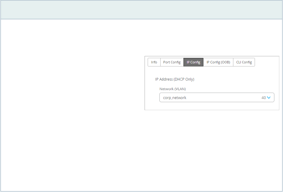
Table 8: Select Switches Conguraon—IP Cong Tab
Opon Notes
Network (VLAN) List Select a network for in-band management trac. Or
click Add Network and complete the New Network
elds as described in the remaining rows of this table.
Name Enter a name to idenfy this network.
VLAN ID Enter the VLAN ID from 1-4094, or enter a site
variable to dynamically enter an ID.
Subnet Enter the subnet or site variable.
Select Switches—IP Cong (OOB) Tab
Enable or disable Dedicated Management VRF (out of band). For all standalone devices or Virtual
Chassis running Junos version 21.4 or later, this feature connes the management interface to non-
default virtual roung and forwarding (VRF) instances. Management trac no longer has to share a
roung table with other control trac or protocol trac.
Select Switches—Port Mirroring Tab
This tab displays the list of port mirroring conguraons already added. Click an entry to edit it. Or click
Add Port Mirror to enable port mirroring. This feature allows you to dynamically apply port mirroring on
switches based on the parameters such as the switch role, switch name, and switch model as specied in
the rules. This feature is typically used for monitoring and troubleshoong. When port mirroring is
enabled, the switch sends a copy of the network packet from the mirrored ports to the monitor port.
The conguraon opons include the following:
• Input—The source (an interface or network) of the trac to be monitored. Along with the input, you
can specify whether you want Mist to monitor the ingress trac or the egress trac for an interface.
61

If you want both ingress and egress trac to be monitored, add two input entries for the same
interface - one with the ingress ag and the other with the egress ag.
• Output—The desnaon interface to which you want to mirror the trac. You cannot specify the
same interface or network in both the input and output elds.
The rules under Select Switches Conguraon take precedence over the global Port Mirroring
conguraon. Also, if the global port mirroring is congured, it is displayed as the default rule in the
Select Switches conguraon secon and is displayed as read-only. You can edit it at the global level.
Select Switches—CLI Cong Tab
Enter addional CLI commands, as needed.
Switch Policy Labels (Beta)
In this secon, add GBP tags to idenfy groups of users and resources to reference in your switch
policies.
NOTE: Only the following devices that run Junos OS Release 22.4R1 and later support GBPs:
EX4400, EX4100, EX4650, QFX5120-32C and QFX5120-48Y.
The following example shows the tags that a user created, along with the policies that reference them.
62

NOTE: This feature is currently available only to beta parcipants.
To get started, click Add GBP tag. Then enter a name, select the type, and enter the value. Then click
Add at the lower-right corner of the screen.
When you enable a tag, you'll see on-screen alert about the impact on standalone switches and virtual
chassis. Read the on-screen informaon before proceeding.
NOTE: If you congure 802.1X authencaon with mulple-supplicant mode, the GBP tagging is
MAC-based. If you congure 802.1X authencaon with single-supplicant mode, the GBP
tagging is port-based.
Table 9: Switch Policy Label (GBP Tag)
Conguraon Opons
Opon Notes
Dynamic or Stac By default, Juniper Mist chooses the Dynamic opon.
If you select Stac, specify a GBP tag source. It can be
a MAC address, network, or an IP subnet.
63

Table 9: Switch Policy Label (GBP Tag) Conguraon Opons
(Connued)
Opon Notes
GBP Tag Enter value or GBP source tag for host-originated
packets (range: 1 through 65535).
Switch Policy (Beta)
Congure Group Based Policies (GBPs) that you can use in your campus fabric IP Clos deployments.
When you create a policy, you use organizaon-level and site-level labels and your GBP tags (from the
Switch Policy Labels secon) to idenfy users who can or cannot access specied resources.
NOTE: Only the following devices that run Junos OS Release 22.4R1 and later support GBPs:
EX4400, EX4100, EX4650, QFX5120-32C and QFX5120-48Y.
The following image shows a sample policy, using tags that were dened in the Switch Policy Labels
secon.
To get started, click Add Switch Policy. Then enter the sengs, as described in the following table.
64

Table 10: Switch Policy Conguraon Opons
Opon Notes
USER/GROUP Click + and add the users or groups that need access to
the resources. You can use the GBT tags here, if you
have dened them already.
RESOURCE Click + and add the resources that you need to map to
the selected users or groups. You can use the GBT tags
here too, if you have dened them already.
By default, users are given access to the resources
added. If you want to deny the user access to certain
resources, click the Resource label that you have added
and set the access to deny.
QoS Conguraon
IN THIS SECTION
Enable QoS on a Switch Port | 67
Override QoS | 69
Verify QoS Sengs (API) | 69
Verify QoS Conguraon Through the CLI | 70
65

NOTE: QoS conguraon is part of the switch conguraon workow described in "Congure
Switches" on page 22. This topic provides more detailed informaon focused solely on QoS
concept and conguraon steps.
Quality of Service (QoS) is a trac-control mechanism that helps you priorize latency-sensive trac
(such as voice) over other trac in a congested network. The QoS implementaon in Juniper Mist™
generally involves the following:
• Classifying trac.
• Dening trac-to-queue mappings (forwarding classes).
• Dening scheduler and re-write rules for each queue. These rules govern the priorizaon,
bandwidth control, and congeson management of the trac on each interface.
• Applying QoS components to the interfaces.
In Juniper Mist, QoS ulizes the Behavior Aggregate (BA) classicaon, where the DiServ code point
(DSCP) or class of service (CoS) values in the incoming trac govern the classicaon. The BA classier
maps a CoS value in the packet header to a forwarding class and loss priority.
Enabling QoS on an interface adds DSCP markings to that port based on the class and rewrite rules. The
QoS mechanism maps the incoming packets with a DSCP marking to one of the seven forwarding
classes listed in the following table:
Code Point/Loss
Priority
Forwarding
Class
Transmit Queue Buer Size(%) Transmit
Rate(%)
Priority
be default-app 0 Remainder Remainder Low
af41/Low af42/
High af43/High
cs4/Low
video 1 8 8 Low
af31/Low af32/
High af33/High
cs3/Low
bizapp-af3 2 10 10 Low
af21/Low af22/
High af23/High
bizapp-af2 3 10 10 Low
66

(Connued)
Code Point/Loss
Priority
Forwarding
Class
Transmit Queue Buer Size(%) Transmit
Rate(%)
Priority
af11/Low af12/
High af13/High
net-tools 4 3 3 Low
cs5/Low ef/Low voice 7 10 10 Strict-high
nc1/Low
nc2/Low
net-control 5 3 3 Low
As shown in the preceding table, the packet classicaon assigns an incoming packet to an output
queue based on the packet’s forwarding class. In case of trac congeson on the link, Juniper Mist
priorizes the latency-sensive trac (for example, voice trac) over other trac (provided that the
incoming trac is marked appropriately). Juniper Mist also congures re-write rules automacally to
retain markings as the packets exit the switch.
Enable QoS on a Switch Port
You can congure QoS on a switch port from the Port Prole le on the switch details page or switch
template.
To enable QoS on a switch port:
1. To congure QoS at the organizaon level, click Organizaon > Switch Templates >
template name
.
Or, if you want to congure QoS at the switch level, click Switches >
switch name
.
2. From the Port Prole le, select the port prole you want to update. Or if you want to create a new
port prole, click Add Prole.
3. In the conguraon, remember to select the QoS check box.
67

68

4. Save the conguraon by clicking the ck mark on the upper right of the port prole conguraon
window.
5. Aer conguring QoS in the port prole, assign the prole to the switch port on which you want to
congure QoS. You can do that from the Port Cong tab in the Select Switches secon of a switch
conguraon template (See "Create a Switch Conguraon Template" on page 23) or from the Port
Conguraon secon on the Switch Details page ("Switch Details" on page 110).
Ensure that you enable QoS for both downstream and upstream port proles, to obtain opmum results.
Override QoS
You also have the opon to override the QoS conguraon on the WLAN sengs page (Site > WLANs >
WLAN name
). To override the QoS conguraon, select the Override QoS check box and choose a
wireless access class (see WLAN Opons). The downstream trac (AP > client) gets marked with the
override access class value specied. The override conguraon doesn't support upstream trac (client
> AP).
For further details on QoS on Juniper EX Switches, please see Example: Conguring CoS on EX Series
Switches. If required, any addional QoS conguraon updates can be done via CLIs in the Addional
CLI Commands secon in the switch details page.
Verify QoS Sengs (API)
The following example has “enable_qos”: true set for the port proles qos-test and uplink. This indicates
that the port prole has QoS enabled.
"port_usages": {
"qos-test": {
"name": "qos-test",
"mode": "access",
"disabled": false,
"port_network": "vl10",
"voip_network": null,
"stp_edge": false,
"all_networks": false,
"networks": [],
"port_auth": null,
"speed": "auto",
69

"duplex": "auto",
"mac_limit": 0,
"poe_disabled": false,
"enable_qos": true
},
"uplink": {
"mode": "trunk",
"all_networks": true,
"stp_edge": false,
"port_network": "vlan3",
"voip_network": null,
"name": "uplink",
"disabled": false,
"networks": [],
"port_auth": null,
"speed": "auto",
"duplex": "auto",
"mac_limit": 0,
"poe_disabled": false,
"enable_qos": true
}
},
Verify QoS Conguraon Through the CLI
The following is a sample QoS conguraon on a switch:
set groups mist-qos-default class-of-service classifiers dscp dscp-classifier-default forwarding-
class bizapp-af2 loss-priority high code-points af22
set groups mist-qos-default class-of-service classifiers dscp dscp-classifier-default forwarding-
class bizapp-af2 loss-priority high code-points af23
set groups mist-qos-default class-of-service classifiers dscp dscp-classifier-default forwarding-
class bizapp-af2 loss-priority low code-points af21
set groups mist-qos-default class-of-service classifiers dscp dscp-classifier-default forwarding-
class bizapp-af3 loss-priority high code-points af32
set groups mist-qos-default class-of-service classifiers dscp dscp-classifier-default forwarding-
class bizapp-af3 loss-priority high code-points af33
set groups mist-qos-default class-of-service classifiers dscp dscp-classifier-default forwarding-
70

class bizapp-af3 loss-priority low code-points af31
set groups mist-qos-default class-of-service classifiers dscp dscp-classifier-default forwarding-
class bizapp-af3 loss-priority low code-points cs3
set groups mist-qos-default class-of-service classifiers dscp dscp-classifier-default forwarding-
class default-app loss-priority low code-points be
set groups mist-qos-default class-of-service classifiers dscp dscp-classifier-default forwarding-
class net-control loss-priority low code-points nc1
set groups mist-qos-default class-of-service classifiers dscp dscp-classifier-default forwarding-
class net-control loss-priority low code-points nc2
set groups mist-qos-default class-of-service classifiers dscp dscp-classifier-default forwarding-
class net-tools loss-priority high code-points af12
set groups mist-qos-default class-of-service classifiers dscp dscp-classifier-default forwarding-
class net-tools loss-priority high code-points af13
set groups mist-qos-default class-of-service classifiers dscp dscp-classifier-default forwarding-
class net-tools loss-priority low code-points af11
set groups mist-qos-default class-of-service classifiers dscp dscp-classifier-default forwarding-
class video loss-priority high code-points af42
set groups mist-qos-default class-of-service classifiers dscp dscp-classifier-default forwarding-
class video loss-priority high code-points af43
set groups mist-qos-default class-of-service classifiers dscp dscp-classifier-default forwarding-
class video loss-priority low code-points af41
set groups mist-qos-default class-of-service classifiers dscp dscp-classifier-default forwarding-
class video loss-priority low code-points cs4
set groups mist-qos-default class-of-service classifiers dscp dscp-classifier-default forwarding-
class voice loss-priority low code-points cs5
set groups mist-qos-default class-of-service classifiers dscp dscp-classifier-default forwarding-
class voice loss-priority low code-points ef
set groups mist-qos-default class-of-service classifiers dscp dscp-classifier-default import
default
set groups mist-qos-default class-of-service forwarding-classes queue 0 default-app
set groups mist-qos-default class-of-service forwarding-classes queue 1 video
set groups mist-qos-default class-of-service forwarding-classes queue 2 bizapp-af3
set groups mist-qos-default class-of-service forwarding-classes queue 3 bizapp-af2
set groups mist-qos-default class-of-service forwarding-classes queue 4 net-tools
set groups mist-qos-default class-of-service forwarding-classes queue 5 voice
set groups mist-qos-default class-of-service forwarding-classes queue 7 net-control
set groups mist-qos-default class-of-service interfaces ge-0/0/0 scheduler-map sched-maps-default
set groups mist-qos-default class-of-service interfaces ge-0/0/0 unit 0 classifiers dscp dscp-
classifier-default
set groups mist-qos-default class-of-service interfaces ge-0/0/0 unit 0 rewrite-rules dscp dscp-
rewriter-default
set groups mist-qos-default class-of-service interfaces ge-0/0/9 scheduler-map sched-maps-default
set groups mist-qos-default class-of-service interfaces ge-0/0/9 unit 0 classifiers dscp dscp-
71

classifier-default
set groups mist-qos-default class-of-service interfaces ge-0/0/9 unit 0 rewrite-rules dscp dscp-
rewriter-default
set groups mist-qos-default class-of-service rewrite-rules dscp dscp-rewrite-default import
default
set groups mist-qos-default class-of-service rewrite-rules dscp dscp-rewriter-default forwarding-
class bizapp-af2 loss-priority low code-point af21
set groups mist-qos-default class-of-service rewrite-rules dscp dscp-rewriter-default forwarding-
class bizapp-af3 loss-priority low code-point af31
set groups mist-qos-default class-of-service rewrite-rules dscp dscp-rewriter-default forwarding-
class default-app loss-priority low code-point be
set groups mist-qos-default class-of-service rewrite-rules dscp dscp-rewriter-default forwarding-
class net-control loss-priority low code-point nc1
set groups mist-qos-default class-of-service rewrite-rules dscp dscp-rewriter-default forwarding-
class net-tools loss-priority low code-point af11
set groups mist-qos-default class-of-service rewrite-rules dscp dscp-rewriter-default forwarding-
class video loss-priority low code-point af41
set groups mist-qos-default class-of-service rewrite-rules dscp dscp-rewriter-default forwarding-
class voice loss-priority low code-point ef
set groups mist-qos-default class-of-service scheduler-maps sched-maps-default forwarding-class
bizapp-af2 scheduler bizapp-af2-scheduler
set groups mist-qos-default class-of-service scheduler-maps sched-maps-default forwarding-class
bizapp-af3 scheduler bizapp-af3-scheduler
set groups mist-qos-default class-of-service scheduler-maps sched-maps-default forwarding-class
default-app scheduler default-scheduler
set groups mist-qos-default class-of-service scheduler-maps sched-maps-default forwarding-class
net-control scheduler net-control-scheduler
set groups mist-qos-default class-of-service scheduler-maps sched-maps-default forwarding-class
net-tools scheduler net-tools-scheduler
set groups mist-qos-default class-of-service scheduler-maps sched-maps-default forwarding-class
video scheduler video-scheduler
set groups mist-qos-default class-of-service scheduler-maps sched-maps-default forwarding-class
voice scheduler voice-scheduler
set groups mist-qos-default class-of-service schedulers bizapp-af2-scheduler buffer-size percent
10
set groups mist-qos-default class-of-service schedulers bizapp-af2-scheduler priority low
set groups mist-qos-default class-of-service schedulers bizapp-af2-scheduler transmit-rate
percent 10
set groups mist-qos-default class-of-service schedulers bizapp-af3-scheduler buffer-size percent
10
set groups mist-qos-default class-of-service schedulers bizapp-af3-scheduler priority low
set groups mist-qos-default class-of-service schedulers bizapp-af3-scheduler transmit-rate
percent 10
72

set groups mist-qos-default class-of-service schedulers default-scheduler buffer-size remainder
set groups mist-qos-default class-of-service schedulers default-scheduler priority low
set groups mist-qos-default class-of-service schedulers default-scheduler transmit-rate remainder
set groups mist-qos-default class-of-service schedulers net-control-scheduler buffer-size
percent 3
set groups mist-qos-default class-of-service schedulers net-control-scheduler priority low
set groups mist-qos-default class-of-service schedulers net-control-scheduler transmit-rate
percent 3
set groups mist-qos-default class-of-service schedulers net-tools-scheduler buffer-size percent 3
set groups mist-qos-default class-of-service schedulers net-tools-scheduler priority low
set groups mist-qos-default class-of-service schedulers net-tools-scheduler transmit-rate
percent 3
set groups mist-qos-default class-of-service schedulers video-scheduler buffer-size percent 8
set groups mist-qos-default class-of-service schedulers video-scheduler priority low
set groups mist-qos-default class-of-service schedulers video-scheduler transmit-rate percent 8
set groups mist-qos-default class-of-service schedulers voice-scheduler buffer-size percent 10
set groups mist-qos-default class-of-service schedulers voice-scheduler priority strict-high
set groups mist-qos-default class-of-service schedulers voice-scheduler shaping-rate percent 10
To verify the trac-matching QoS policies and their corresponding queue counters:
1. Review the current interface stascs and CoS informaon by running the following command:
root@ex2300-home> show interfaces ge-0/0/0 extensive
......
Queue counters: Queued packets Transmitted packets Dropped packets
0 0 0 0
1 0 0 0
2 0 0 0
3 0 0 0
4 0 0 0
5 0 0 0
7 0 0 0
Queue number: Mapped forwarding classes
0 default-app
1 video
2 bizapp-af3
3 bizapp-af2
4 net-tools
5 voice
7 net-control
73

......
CoS information:
Direction : Output
CoS transmit queue Bandwidth Buffer Priority Limit
% bps % usec
0 default-app r r r 0 low none
1 video 8 80000000 8 0 low none
2 bizapp-af3 10 100000000 10 0 low none
3 bizapp-af2 10 100000000 10 0 low none
4 net-tools 3 30000000 3 0 low none
5 voice r r 10 0 strict-high none
7 net-control 3 30000000 3 0 low none
Interface transmit statistics: Disabled
2. Generate some video and voice trac. The device marks the trac with DSCP values (queue 1 for
video trac and queue 5 for voice trac).
ping 8.8.8.8 -I eth0 -Q 184
PING 8.8.8.8 (8.8.8.8) from 10.0.0.2 eth0: 56(84) bytes of data.
53 packets transmitted, 53 received, 0% packet loss, time 140ms
rtt min/avg/max/mdev = 2.421/2.811/5.064/0.428 ms
ping 8.8.8.8 -I eth0 -Q 136
PING 8.8.8.8 (8.8.8.8) from 10.0.0.2 eth0: 56(84) bytes of data.
62 packets transmitted, 62 received, 0% packet loss, time 157ms
rtt min/avg/max/mdev = 2.396/3.103/6.578/0.609 ms
3.
Run the show interfaces ge-0/0/0 extensive command again. You can view the packet counts displayed
under Queued Packets and Transmied Packets.
root@ex2300-home> show interfaces ge-0/0/0 extensive
.......
Egress queues: 8 supported, 7 in use
Queue counters: Queued packets Transmitted packets Dropped packets
74

0 9821 9821 0
1 62 62 0
2 0 0 0
3 7185 7185 0
4 0 0 0
5 53 53 0
7 0 0 0
Queue number: Mapped forwarding classes
0 default-app
1 video
2 bizapp-af3
3 bizapp-af2
4 net-tools
5 voice
7 net-control
.......
CoS information:
Direction : Output
CoS transmit queue Bandwidth Buffer Priority Limit
% bps % usec
0 default-app r r r 0 low none
1 video 8 80000000 8 0 low none
2 bizapp-af3 10 100000000 10 0 low none
3 bizapp-af2 10 100000000 10 0 low none
4 net-tools 3 30000000 3 0 low none
5 voice r r 10 0 strict-high none
7 net-control 3 30000000 3 0 low none
Interface transmit statistics: Disabled
See also: Example: Conguring CoS on EX Series Switches
Congure SNMP on Switches
IN THIS SECTION
Congure SNMP at the Organizaon Level | 76
Congure SNMP at the Site Level | 78
75

Congure SNMP at the Device Level | 80
NOTE: SNMP conguraon is part of the switch conguraon workow described in "Congure
Switches" on page 22. This topic provides more detailed informaon focused solely on SNMP
conguraon steps.
Simple Network Management Protocol (SNMP) enables network administrators to monitor and manage
network-connected devices in IP networks (see SNMP Architecture and SNMP MIBs Overview).
In a switch, SNMP is disabled by default. If required, you can enable it at the organizaon level (from the
organizaon level switch templates), site level (from the site level switch templates) at device level (from
the switch details page.)
Mist allows you to congure SNMP V2 or SNMP V3 sengs.
Congure SNMP at the Organizaon Level
If you want to apply SNMP to all the switches in the enre organizaon (all sites), you can do that at the
organizaon level.
To congure SNMP at the organizaon level:
1. Click Organizaon > Switch Templates.
2. Click Create Template if you want to congure SNMP as part of a new switch template. For more
informaon, see "Create a Switch Conguraon Template" on page 23.
Or, if you want to update an exisng template with SNMP conguraon, click that template to open
it.
3. On the SNMP le (in the All Switches Conguraon secon), click the Enabled check box.
76

4. Specify the SNMP informaon, which includes General informaon, Clients, Trap Groups,
Community, and Views. Mist supports the SNMP versions V2 and V3. For the eld descripons, refer
to the SNMP informaon in the All Switches Conguraon Opons table in "All Switches" on page
30.
The conguraon elds appear based on the selecon of SNMP version (V2 or V3).
5. Save the template.
6. Assign the template to a site. For instrucons to do so, see "Assign a Template to Sites" on page 24.
77

Congure SNMP at the Site Level
You can choose to have SNMP conguraon to specic sites in an organizaon. If the SNMP is disabled
at the organizaon level but you want to enable it at a parcular site, you can override the organizaon
templates sengs inherited by that site. If you congure SNMP at the site level, the conguraon gets
applied to all the switches in that site. Any update in the site-level sengs does not override the values
in the associated organizaon template. The change is applied only to the selected site.
To congure SNMP at the site level:
1. Click Site > Switch Conguraon.
2. Click the site, where you want to congure SNMP, to open it.
3. Scroll down to the SNMP le in the All Switches Conguraon secon.
4. Select the Override Conguraon Template check box.
5. Click the Enabled check box in the SNMP le.
78

6. Specify the SNMP informaon, which includes General informaon, Clients, Trap Groups,
Community, and Views. Mist supports the SNMP versions V2 and V3. For the eld descripons, refer
to the SNMP informaon in the All Switches Conguraon Opons table in "All Switches" on page
30.
The conguraon elds appear based on the selecon of SNMP version (V2 or V3).
7. Save the conguraon.
79

Congure SNMP at the Device Level
If you want to congure SNMP for specic switches in a site, you can do that from the switch details
page. If the SNMP is disabled at the site level but you want to enable it for a specic switch, you can
override the site templates sengs inherited by that switch. Any update in the switch-level sengs
does not override the values in the associated site or organizaon template sengs. The change is
applied only to the selected switch.
Mist allows you to congure a poron of SNMP sengs at the switch level and use the remaining
poron from the template. This means you can merge the SNMP values congured at the switch-level
with the SNMP values that the switch inherited from a site-level or organizaon-level template. This
feature is helpful when you want the switch to use some SNMP values from the switch-level
conguraon and some from the associated template. For example, you can use the name and locaon
from the switch-level conguraon and everything else from the associated template.
NOTE: Before you congure SNMP at the switch level, ensure that the switch is in connected
state with stable connecvity to cloud.
To congure SNMP at the switch level:
1. Click Switches >
Switch Name
.
2. Click the switch (to be updated) from the list to open it.
3. Scroll down to the SNMP le in the Services secon.
4. Select the Override Site/Template Sengs check box.
5. Click the Enabled check box in the SNMP le.
80

6. Specify the SNMP informaon, which includes General informaon, Clients, Trap Groups,
Community, and Views. Mist supports the SNMP versions V2 and V3. For the eld descripons, refer
to the SNMP informaon in the All Switches Conguraon Opons table in "All Switches" on page
30.
The conguraon elds appear based on the selecon of SNMP version (V2 or V3).
7. Save the conguraon.
81

Congure DHCP Server or Relay on a Switch
IN THIS SECTION
Prerequisites | 82
Congure DHCP Server | 82
Congure DHCP Relay | 89
This chapter lists the steps that are required to congure DHCP server or relay on a switch.
Prerequisites
Before conguring the DHCP server or relay, ensure the following:
• The VLAN for which DHCP server will be congured on switch is assigned to the ports connecng to
the DHCP clients. You can do this by applying a relevant port prole to the port. For more
informaon about port proles, see "Port Proles Overview" on page 9.
• The switch has a Stac IP Conguraon or Addional IP conguraon for the network to run DHCP
server. Or the L3 Interface is congured for DHCP server or relay.
Congure DHCP Server
To congure DHCP server on a switch:
1. Navigate to Switches on the le menu and then click a Switch from the list.
The switch details page is displayed.
2. On the switch details page, scroll down to the DHCP Server / Relay le in the Services secon.
82

3. On the DHCP Server / Relay le, select the Enabled check box and then click Add DHCP Network.
The DHCP Server / Relay conguraon window is displayed.
4. Ensure that Server is selected as conguraon Type.
5. From the Network drop-down list, select a network for the DHCP server.
6. Specify the following elds:
• IP Start—The starng IP address within the DHCP IP address assignment pool.
• IP End—The ending IP address within the DHCP IP address assignment pool.
• Gateway—Default gateway for the DHCP client. Usually, it is the switch IRB IP address for the
corresponding network.
• DNS Servers (Oponal)—You can add up to three DNS IP addresses in a comma separated format.
• DNS Sux (Oponal)—You can add up to three domain suxes in a comma separated format.
83

If you do not congure the DNS Servers and DNS Sux, Mist auto-generates the conguraon by
taking DNS servers and DNS Sux congured at the switch level.
7. Save the changes.
The following conguraon will be applied to the API /sites/:site-id/devices/device-id:
84

Check the corresponding intended conguraon to be pushed to the following API: /sites/:site-id/
devices/device-id/config_cmd
The DHCP server is enabled on the irb.10 interface for the vl10.
set groups top system services dhcp-local-server group vl10 interface irb.10
The address assignment pool conguraon looks like the below:
"set groups top access address-assignment pool vl10 family inet network 10.0.0.0/24",
"set groups top access address-assignment pool vl10 family inet range vl10 low 10.0.0.100",
"set groups top access address-assignment pool vl10 family inet range vl10 high 10.0.0.200",
"set groups top access address-assignment pool vl10 family inet dhcp-attributes name-server
8.8.8.8",
"set groups top access address-assignment pool vl10 family inet dhcp-attributes name-server
8.8.4.4",
"set groups top access address-assignment pool vl10 family inet dhcp-attributes name-server
1.0.0.1",
"set groups top access address-assignment pool vl10 family inet dhcp-attributes router
10.0.0.10",
"set groups top access address-assignment pool vl10 family inet dhcp-attributes option 15
85

array string test.net",
"set groups top access address-assignment pool vl10 family inet dhcp-attributes option 15
array string tesing1.net",
"set groups top access address-assignment pool vl10 family inet dhcp-attributes option 15
array string testing3.net,"
8. Verify the conguraon on the switch by using the following CLI:
86

87

The DHCP clients for v110 networks should now be assigned IP address by DHCP server as shown
below:
Here are some useful Junos CLI commands:
• show dhcp server binding or show dhcp server binding detail—To view the DHCP server binding
informaon.
• show dhcp server statistics—To view the DHCP messages sent/received stascs.
• clear dhcp server binding interface x-x/x/x—To clear the DHCP client binding for a client on a parcular
interface.
•
clear dhcp server binding <address>—To clear the DHCP client binding based on an IP address or MAC
address of the wired client.
88

Congure DHCP Relay
To congure DHCP relay on a switch:
1. Navigate to Switches on the le menu and then click a Switch from the List.
The switch details page is displayed.
2. On the switch details page, scroll down to the DHCP Server / Relay le in the Services secon.
3. On the DHCP Server / Relay le, select the Enabled check box and then click Add DHCP Network.
The DHCP Server / Relay conguraon window is displayed.
4. Select Relay as conguraon Type.
5. From the Network drop-down list, select a network for the DHCP relay.
6. In the DHCP Servers eld, congure the IP address for the remote DHCP server. You can add up to
three IP addresses in a comma separated format.
89

7. Save the changes.
The following conguraon will be applied to the API /sites/:site-id/devices/device-id:
Check the corresponding intended conguraon to be pushed on following API: /sites/:site-id/
devices/device-id/config_cmd
The conguraon looks like the below:
"set groups top forwarding-options dhcp-relay server-group v111 192.168.1.1",
"set groups top forwarding-options dhcp-relay server-group v111 interface irb.11",
"set groups top forwarding-options dhcp-relay server-group v111 active server group v111",
8. Verify the conguraon on the switch using the following CLI:
90

9. Make sure the remote DHCP server is reachable from the switch.
10. Verify DHCP relay binding on the switch.
91

Here are some useful Junos CLI commands:
• show dhcp relay binding or show dhcp relay binding detail—To view the DHCP relay binding informaon.
• show dhcp server statistics—To view the DHCP relay messages sent/received stascs.
• clear dhcp relay binding interface x-x/x/x—To clear the DHCP client binding for a client on a parcular
interface.
• clear dhcp relay binding <address>—To clear the DHCP client binding based on an IP address or MAC
address of the wired client.
See also: DHCP Relay Agent.
Manage or Update Conguraon Sengs
SUMMARY
You can manage conguraon sengs at the
template level, site level, and device level.
IN THIS SECTION
Manage Templates Sengs | 93
92

Update Switch Conguraon Sengs at the
Site Level | 94
Add or Delete a CLI Conguraon | 94
Manage Templates Sengs
The mist portal provides you opons to modify, clone, export, or delete a template. If you modify a
template, conguraons of all the switches managed by that template are modied. You can use the
Export opon to download the template sengs in JSON format. You can store the JSON le in your
local machine and use it to quickly create new templates, using the Import opon on the template
creaon page.
To modify a template:
1. Click Organizaon > Switch Templates.
2. Click the template you want to modify. The template opens.
3. Modify the sengs. For eld descripons and addional informaon, refer to "Create a Switch
Conguraon Template" on page 23.
4. Aer modifying the template sengs, click Save.
To clone a template:
1. Click Organizaon > Switch Templates.
2. Click the template you want to clone. The template opens.
3. Click More > Clone.
4. Enter a template name and then click Clone. A new template, based on the selected template, is
created.
To export a template:
1. Click Organizaon > Switch Templates.
2. Click the template you want to export. The template opens.
3. Click More > Export. The template is downloaded in a JSON le.
To delete a template:
1. Click Organizaon > Switch Templates.
2. Click the template you want to delete. The template opens.
93

3. Click Delete Template on the top right.
4. On the Conrm Delete window, click Delete. The deleted template is removed from the template list
and from all the sites to which it was assigned.
Update Switch Conguraon Sengs at the Site Level
Aer applying a template to a site, you can:
• Customize or edit the sengs applied to a parcular site, if required. You can also replace or unlink a
template from the site conguraon page.
• Congure addional switch-specic sengs from a switch page. The switch-specic sengs include
a switch name, role, management interface (out of band), and an IRB interface.
To edit the site-level switch conguraon sengs:
1. Click Site > Switch Conguraon.
2. Click a site from the list to open it.
3. If you want to replace the enre template, select the desired template from the Conguraon
Template drop-down list. If you select the value (none), the exisng template gets unlinked from the
site.
4. To edit specic template sengs of the site:
a. Select the Override Conguraon Template in relevant conguraon le.
b. Edit the sengs and then click Save. The changes are immediately applied to the switches in the
site. For more informaon, see "Create a Switch Conguraon Template" on page 23.
Add or Delete a CLI Conguraon
The CLI command opons on the switch conguraon pages in the Juniper Mist™ portal let you
congure features that the predened drop-down lists and text elds on the Mist portal do not support.
You can add a CLI conguraon to a switch by using the set command through the Mist portal. Example:
set system ntp server 192.168.3.65.
Similarly, you can remove a CLI conguraon from a switch by using the delete command through the
Mist portal. Example: delete system ntp server 192.168.3.65.
To add or delete a CLI conguraon:
94

1. Click Switches to go to the Switches page.
2. Click your switch from the list to open the switch conguraon page.
3. Navigate to the relevant CLI commands box (Addional CLI commands).
You can also make CLI changes in the Site/Template CLI Commands and Rule-based CLI Commands
boxes available through the switch templates (Organizaon > Switch Templates).
4. To add a CLI conguraon, enter the set command. For example, set system ntp server 192.168.3.65.
5. To remove a conguraon, replace set with delete in the command. For example, delete system ntp
server 192.168.3.65.
The following image shows the delete operaon.
When you save the delete commands, the following operaons take place:
• Mist sends the delete commands to the switch.
• The Switch Insights page on the Mist portal generates a Cong Changed by User event, with a
response UI_COMMIT_COMPLETED. You can access Switch Insights from "Switch Details" on page
110.
• Mist deletes the CLI commands from the switch. Later, if required, you can remove these commands
from the CLI commands box on the Mist portal.
• Mist updates the delete commands in the following API call:
https://api.mist.com/api/v1/sites/<site_id>/devices/00000000-0000-0000-1000-<switch_mac>/
config_cmd
Just selecng a few commands from any CLI command box on the Mist portal and hing the Backspace
or Delete buon does not remove the commands from the switch. It removes the commands only from
the API, which contains the current switch conguraon that is present on the Mist portal.
95

Deleng the CLI commands only from the GUI also generates a Cong Changed by User event on the
Switch Insights page. However, this event doesn't show the UI_COMMIT_COMPLETED response. The
changes are made only on the Mist portal GUI, not on the switch.
We don't recommend logging in to the switch CLI and making any changes there if the Mist cloud
manages your switch. The changes you make on a switch through the CLI don't get included in the
switch conguraon in the Mist cloud.
Upgrade Junos OS Soware on Your Switch
IN THIS SECTION
Free Up Storage Space on Your Switch | 96
Upgrade the Junos OS Soware on Your Switch | 99
You can upgrade the Junos OS version running on your switch from the Juniper Mist™ portal.
Before upgrading the Junos OS soware running on your switch, ensure that the switch has the
following:
• The storage space required to accommodate the new image.
• A stable SSH connecon to the Mist cloud.
Free Up Storage Space on Your Switch
When you iniate the switch upgrade process, Juniper Mist™ runs the request system storage cleanup
command on the switch before copying the soware image. This process mostly ensures the availability
of storage space to accommodate the soware image in the /var/tmp folder on the switch. However, in
the case of some switches, such as EX2300 and EX3400, the request system storage cleanup command
doesn't clear the required space. In this case, you will need to free up more space.
NOTE:
96

• To perform the steps listed in this topic, you must have the root password congured in the
site sengs on the Organizaon > Site Conguraon page of the Juniper Mist portal.
• Perform the steps listed in this topic only if your switch doesn't have the required space for
the upgrade.
To free up storage space on your switch:
1. On the Juniper Mist portal, click Switches to go to the list of switches.
2. Locate the switch on which you want to perform the storage cleanup operaon.
3. Select Ulies > Remote Shell.
4. Begin a shell session by entering the start shell user root command, followed by the root password.
{master: 0}
mist@Mist_Sw> start shell user root
Password:
root@Mist_Sw:RE:0%
This step starts a shell session on the primary FPC member by default.
5. Check the storage usage, by running the df -h command.
Generally, the /dev/gpt/junos le system takes up most of the space.
user@Mist_Sw:RE:0% df -h
Filesystem Size Used Avail Capacity Mounted on
/dev/md0.uzip 22M 22M 0B 100% /
devfs 1.0K 1.0K 0B 100% /dev
/dev/gpt/junos 1.3G 941M 315M 75% /.mount
...output truncated...
6. Run the following command to free up the space on the switch:
root@Mist_Sw :RE:0% pkg setop rm previous
root@Mist_Sw :RE:0% pkg delete old
97

7. Check the available storage, using the df -h command. The output now shows lesser space as used
under /dev/gpt/junos.
user@Mist_Sw:RE:0% df -h
Filesystem Size Used Avail Capacity Mounted on
/dev/md0.uzip 22M 22M 0B 100% /
devfs 1.0K 1.0K 0B 100% /dev
/dev/gpt/junos 1.3G 567M 689M 45% /.mount
...output truncated...
8. Exit the shell session to return to the CLI operaonal mode, and then check the storage usage from
there.
user@Mist_Sw:RE:0% exit
exit
{master :0}
user@Mist_Sw> show system storage
Filesystem Size Used Avail Capacity Mounted on
/dev/gpt/junos 1.3G 941M 315M 75% /.mount
tempfs 393M 68K 393M 0% /.mount/tmp
tempfs 324M 576K 324M 0% /.mount/mfs
...output truncated...
In the case of a Virtual Chassis upgrade, the preceding steps free up the space only on the primary
member (member 0). You also need to iniate a session with each of the other FPC members (such as
member 1 and member 2) and repeat the storage cleanup steps. See the following example:
user@Mist_Sw> request session member 1
Last login: Tue Feb 16 00:42:30 from 13.56.90.212...
mist@Mist_Sw> start shell user root
Password:
user@mist_sw:RE:0% df -h
Filesystem Size Used Avail Capacity Mounted on
98

/dev/md0.uzip 22M 22M 0B 100% /
devfs 1.0K 1.0K 0B 100% /dev
/dev/gpt/junos 1.3G 916M 340M 73% /.mount
...output truncated...
Upgrade the Junos OS Soware on Your Switch
The Juniper Mist™ portal supports upgrading the Junos OS soware on the following plaorms:
EX2300, EX3400, EX4100, EX4100-F, EX4300-P, EX4300-MP, EX4400, EX4600, EX4650, EX9200,
QFX5110, QFX5120, and EX Series Virtual Chassis.
In the case of Virtual Chassis, you can only upgrade the mixed EX4300 Virtual Chassis, which combines
EX4300 mulgigabit model (EX4300-48MP) switches with any other EX4300 model switches. Juniper
Mist does not support nonstop soware upgrade (NSSU).
For both standard EOL and EEOL releases, you can upgrade to the next three subsequent releases or
downgrade to the previous three releases. For example, you can upgrade from 21.2 to the next three
releases – 21.3, 21.4 and 22.1 or downgrade to the previous three releases – 21.1, 20.4 and 20.3.
For EEOL releases, you have an addional opon - you can upgrade directly from one EEOL release to
the next two subsequent EEOL releases, even if the target release is beyond the next three releases.
Likewise, you can downgrade directly from one EEOL release to the previous two EEOL releases, even if
the target release is beyond the previous three releases. For example, 21.2 is an EEOL release. Hence,
you can upgrade from 21.2 to the next two EEOL releases – 21.4 and 22.2 or downgrade to the
previous two EEOL releases – 20.4 and 20.2. Check Junos OS Dates and Milestones to see whether a
release has reached EEOL.
To upgrade the Junos OS soware on your switch:
1. Click Switches on the le navigaon pane in the Juniper Mist portal.
2. Locate the switch to be upgraded, and ensure that it is connected (displays the Connected status).
If the switch doesn't appear on Mist as connected, troubleshoot the issue as explained in
"Troubleshoot Your Switch" on page 216.
99

3. From the List tab, select the switches that require a soware upgrade, and then click Upgrade
Switches. You can select one or more switches for the upgrade.
Alternavely, you can also upgrade the switch by using the Upgrade Firmware opon on the Ulies
drop-down list on the switch details page (see "Switch Details" on page 110).
4. In the Upgrade Switch Firmware window, select the target soware version from the Upgrade to
Version drop-down list, and then click Start Upgrade. The drop-down list displays the suggested
soware version for the selected switch, along with all the applicable versions.
100

If you don't see the soware version you are looking for, write to [email protected]. We will make
the version available from 24 to 48 hours aer receiving the request. See also: Junos Soware
Versions - Suggested Releases to Consider and Evaluate.
Select the Reboot switch aer image copy check box if you want the switch to reboot automacally
aer the image copy procedure is complete.
• If you select this opon, the switch boots up with the new image.
• If you do not select this opon, the switch remains in a state of pending reboot. In this case, do
the following to complete the upgrade:
a. Navigate to the switch details page (Switches >
Switch Name
).
b. Reboot the switch from Ulies > Reboot Switch.
Once the upgrade starts, the Status column in the switch list view shows the switch status as Upgrading.
The column also shows the progress of the upgrade.
If you don't see the Status column in the switch list view, click the hamburger menu in the upper right of
the page. Select the Status check box to display the column.
You can also view the switch status (as Upgrading) on the switch details page and the Switch Insights
page.
101

You can view the upgrade events in the Switch Events secon of a Switch Insights page. To access the
Switch Insights page, open a "switch details" on page 110 page and click the Switch Insights link on the
Properes le.
The above image shows a Switch Insights page, which lists switch upgrade events. The Upgraded by
User event indicates that a user has iniated the upgrade. The Upgraded event indicates that the
upgrade operaon is complete. This means that the new soware image was copied and the switch was
rebooted.
An upgrade will fail if:
• The switch doesn't have an SSH connecon to the Juniper Mist cloud or if an uplink port is apping.
• The switch doesn't have enough storage. If the upgrade fails because of insucient space, the
upgrade failure event is displayed on the Switch Insights page as shown below:
See also: "Free Up Storage Space on Your Switch" on page 96
• You iniate an upgrade to the same soware version that is already running on the switch. In this
case, the Switch Events secon of the Switch Insights page shows this failure reason:
Upgrade not needed. Please check current or pending version.
• The me on the switch is incorrect. In this case, the Switch Events secon of the Switch Insights
page shows this failure reason:
OC FWUPDATE WRITEFAILED. See also: [EX/QFX] Cercate errors - Cannot validate Junos
Image : Format error in cercate.
102

Assign a Role to Switches
You can select and apply a role to an individual switch from the switch details page or from the switch
list. This feature ensures that a switch does not inherit a role that does not exist. The role you assign to a
switch should exist in the conguraon template associated with the selected switch. A switch can have
only one role at a me.
You can create new switch roles as part of Select Switches Conguraon rules in a switch template
(Organizaon > Switch Templates or Sites > Switch Conguraon). See also: "Congure Switches" on
page 22.
To assign a role to a switch:
1. Click Switches to go to the switch list.
2. Idenfy the switch that you want to assign a role to and then select the switch check box.
3. On the More menu, click Assign Switch Role.
4. In the Role eld, specify the switch role and then click OK. Click inside the Role eld to view all the
available roles. The Role eld displays the switch roles that exist in the conguraon template
associated with the selected switch.
Alternavely, navigate to the switch details page (Switches > Switch-Name), specify the switch role in
the INFO secon, and save the conguraon (see the image below).
103

Replace a Switch
You can replace a switch in your Juniper Mist™ network from the switch details page without disrupng
network services.
Before replacing a switch, ensure the following:
• The old switch that needs to be replaced is claimed or adopted by your organizaon and is assigned
to a site. This switch can be in Connected or Disconnected state.
• The new switch being added is not assigned to any site in the organizaon. Furthermore, the new
switch is listed on the Inventory page with the status Unassigned.
To replace a switch:
1. Click Switches on the le navigaon pane of the Mist portal.
2. On the list tab, click the switch that needs to be replaced.
The "switch details" on page 110 page appears.
3. Select the Replace Switch opon from the Ulies drop-down list on the details.
104

4. From the MAC Address of the unassigned switch drop-down list, select the MAC address of the
unassigned switch. This is the replacement switch—the switch you will use to replace the switch that
you selected in Step 2. If the Mist network doesn't include any unassigned switches, the Mist portal
doesn't display unassigned switches. In that case, this drop-down list doesn't show any MAC
addresses.
105
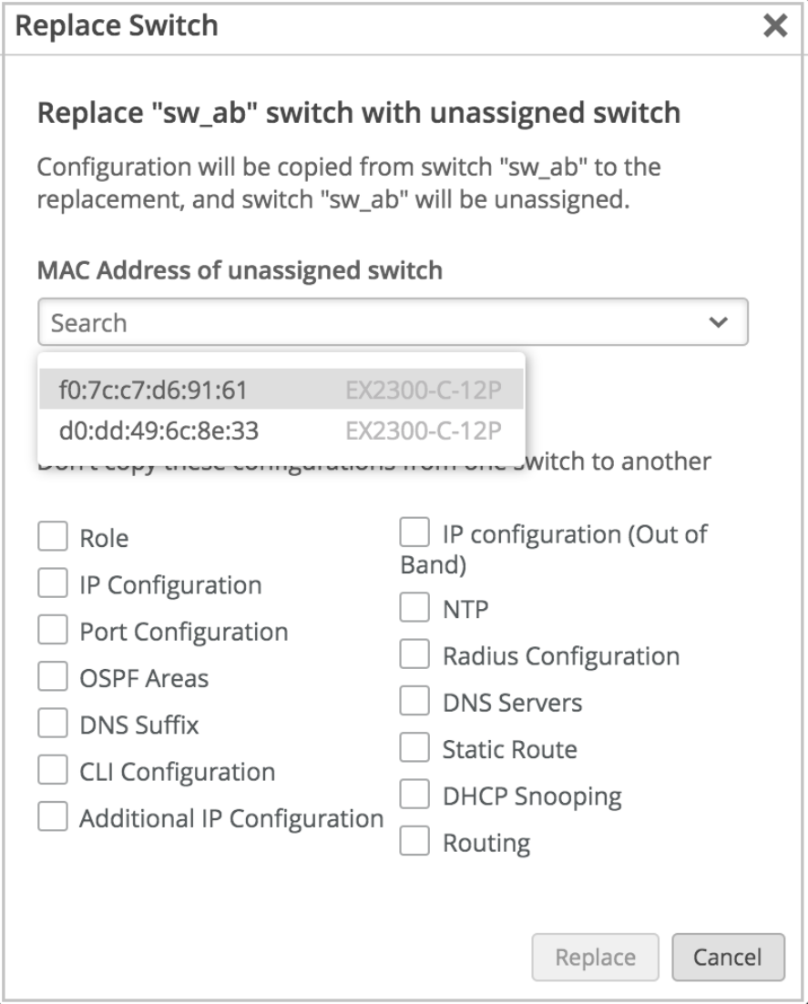
By default, Mist copies the conguraon of the exisng switch to the new switch. To discard any
specic conguraons that you don't want to copy to the new switch, select the appropriate check
boxes on the Replace Switch window.
If the new switch has a dierent number of ports than the switch being replaced, Mist discards the
port conguraon automacally. If the current switch template on the site doesn't cover the
106

conguraon requirement of your new switch, we recommend that you assign a dierent template.
Assign your site a template with a conguraon that meets the requirements of the new switch. See
"Congure Switches" on page 22.
5. Click Replace.
When Mist replaces the switch, the new switch takes the place of the old switch on the Mist portal.
The status of the old switch changes to Unassigned. You can view the old switch on the Inventory
page.
Switch replacement using APIs
To replace a switch using APIs, make a POST API call as shown in the example below:
POST /api/v1/orgs/:org_id/inventory/replace
{
"site_id": "4ac1dcf4-9d8b-7211-65c4-057819f0862b",
"mac": "5c5b35000101",
"inventory_mac": "5c5b35000301",
"discard": []
}
On the discard list, you can specify the aributes that you do not want to copy to the new switch
conguraon. If the discard list is blank, Mist copies all the exisng switch aributes from the old switch
to the new switch.
NOTE:
• If a switch with a higher number of ports is being replaced with a switch with a lower number
of ports, the port conguraon is applied only to the ports with overlapping port numbers.
The rest of the port conguraons are discarded.
• If a switch with mge ports is being replaced with a switch with ge ports or vice versa, the port
conguraons are not applied to the switch.
107


Switch Metrics
The metrics on the Switches page help you track the switch performance against certain
compliance parameters.
To view switch metrics, click Switches on the le navigaon pane on the Mist portal.
Figure 2: Switch Metrics on the Switches Page
Here's a list of the switch metrics you can track:
• Switch-AP Anity—This indicator shows the weighted percentage of the switches for which
the number of APs connected exceeds the threshold congured. By default, the Switch-AP
Anity threshold is set to 12 APs per switch. You can congure a threshold value for the
number of APs per switch to be considered in the Switch-AP Anity metric calculaon. To
congure the AP threshold, click the Switch-AP Anity indicator, and then click the hamburger
icon on the right of the Switch-AP Anity secon.
• PoE Compliance—This indicator shows the percentage of APs that have the required 802.3at
power. PoE compliance is impacted when the APs draw more power from the switch than what
is allocated.
• VLANs—This indicator shows the percentage of APs for which all the wired VLANs are acve.
Click this indicator to view the list of switches and APs that have inacve or missing VLANs,
along with the port informaon.
• Version Compliance— This indicator shows the percentage of switches that have the same
Junos soware version (per switch model). To achieve 100 percent version compliance, you
must ensure that all the switches in your site run the same Junos version per switch model.
• Switch Upme—This indicator shows the percentage of me a switch was up during the past
seven days, averaged across all switches. Click this indicator to view the list of switches that
had less than 100 percent upme during the past 7 days.
You can click each of the switch metric indicators to get a ltered view and quickly access each
device dashboard.
For more details on the switch metrics, watch the following video:
109

Video: Switch Metrics Overview
Switch Details
IN THIS SECTION
Front Panel | 111
Port List | 115
Switch Insights | 116
Metrics | 117
Switch Ulies | 117
Switch Conguraon | 117
The switch details page is your ulmate go-to place on Mist for everything you need to know about a
switch. You can view the status of each port and the stascs of the devices connected to the switch,
access the switch conguraon, review and modify the conguraon, and track how the switch is
performing against key metrics that maer to you.
The switch details page also has the tools that help you with switch tesng and troubleshoong.
To access a switch details page:
1. Open the Mist portal and click Switches on the le pane.
2. Select a switch from the List tab.
You can use the Site drop-down list to lter the switches by a site.
Here's an example of the details page of a switch named ld-cup-idf-a-sw22.
110
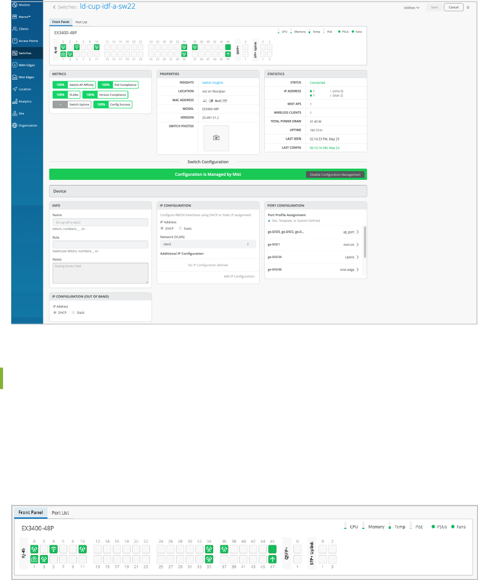
Front Panel
When you open a switch details page, you'll nd yourself on the Front Panel tab. This tab gives you a
comprehensive overview of the switch's port panel.
In this Front Panel view, you get a logical representaon of the switch's ports. You can view the port
status, port conguraon, and the clients or APs connected to each port. The following image
represents a sample Front Panel.
The port icons on the Front Panel view help you quickly idenfy the client devices or APs connected to
each port and their status. The following table lists the key port icons and their descripons:
111

Table 11: Port Icons and Their Descripons
Port Icon Descripon
The port is empty. No device is connected.
A wired client is connected.
A wired client is connected (trunk port).
A Mist AP is connected.
A camera is connected. This icon applies only to
Verkada cameras.
Virtual Chassis port (VCP). A member device is
connected.
The port is up.
Somemes, when a switch port is learning mulple
MAC addresses on the same interface, the switch
cannot idenfy which device is connected to the port.
When that happens, the Mist portal might not display
the connected device as a wired client, even though
the port icon stays solid green. However, if the
connected device has LLDP enabled, the portal
idenes which device is connected to the port.
The port is empty, with acve alerts.
A wired client is connected, but the port has acve
alerts.
112

Table 11: Port Icons and Their Descripons
(Connued)
Port Icon Descripon
A Mist AP is connected, but the port has acve alerts.
An uplink is connected. But the port has acve alerts.
For a sneak peek into what's happening on a specic port, simply hover your mouse over the port. You
can view the type of device connected to the port, the port speed, power sengs, IP address, and much
more.
Here's an example of what you might see if you hover over port ge-0/0/45:
To get a more detailed view of what's going on with a port, click that port to select it. When you select a
port from the front panel, the following happens:
• If you select mulple ports, the conguraon page displays the Port Conguraon, Networks, and
Port Proles les with the sengs applied to the selected ports. You can make conguraon
113

adjustments to the ports from these les. If the selected ports do not have any conguraon, the
Port Conguraon, Networks, and Port Proles les are displayed without any data.
• If you select only a single port, the conguraon page addionally displays port Stascs and Wired
Client insights. From the Wired Client insights le, you can access the connected devices.
From the detailed view of the port, you can also bulk edit the port conguraon, perform cable tests,
bounce (restart) the port in case you encounter any issues with it, and clear MAC addresses stored
through persistent MAC learning.
To bulk edit your port conguraon or override any exisng port conguraon on a switch, select the
ports to be congured from the Front Panel on the switch details page, and click Modify Port
Conguraon (shown in the above picture). In case the selected ports are already part of an exisng port
range conguraon, a warning message indicang the same is displayed. When you save the new
conguraon, it will replace the exisng conguraon for the selected ports. Previously, you had to
manually remove any port conguraon overlap before you carry out a bulk port edit.
On the right side of the front panel, you can also see the device usage indicators. To view the usage
informaon, hover over the indicators on the upper right of the screen. For example, you can see the
temperature values of each component that contribute to the total temperature of the switch.
114

All in all, this detailed view and the addional features make managing your switch a breeze.
Port List
If you want to see a list of all the ports, just click the Port List tab right beside the Front Panel tab.
In this Port List view, you'll nd a wealth of informaon about each port. You can see the port name, its
status, the clients connected to it, the power draw, port prole, port mode, port speed, and even the
amount of data transmied and received. You can also access each connected client by clicking the
client name hyperlink.
By default, Port List displays a select set of columns. You can add more columns to the view from the list
of available columns. To do that, go to Table Sengs by clicking the hamburger menu in the upper right
of the page. From the Table Sengs page, select a check box to display the corresponding column (see
the image below).
115

Switch Insights
If you want to gain valuable insights into your switch, the events such as switch conguraon changes,
performance, and connected endpoints, visit the Switch Insights page by clicking the Switch Insights
hyperlink on the Properes le.
NOTE: You also can go to the Switch Insights page by using the hyperlink on the main Switches
page.
Switch Insights gives you a bird's-eye view of all the switch events that have taken place. It's like a log of
conguraon changes, soware updates, and system alarms.
Switch Insights also lets you track some important metrics like CPU and memory ulizaon of the
switch. You can also dive into details about BGP neighbors (applicable to campus fabrics). You can also
view trac paerns, port errors, and power draw at the switch or port level.
The key secons on the Switch Insights page are the following:
• Switch Events—Provides a log of all the switch events reported. You can lter good, neutral, and bad
events.
• Table Capacity—Provides the following indicators:
• MAC Address Table—Displays the percentage of the MAC address table capacity used. The MAC
address table contains MAC Address-interface bindings associated with each VLAN.
• ARP Table—Displays the percentage of Address Resoluon Protocol (ARP) table capacity used.
The ARP table contains the learned MAC Address-IP bindings of the devices connected to the
network.
• Route Summary—Displays the percentage of roung table capacity used.
• EVPN Database—Available for switches that are part of an EVPN topology.
You can click the Search Entries buon under each metric to open a shell view in a new window
where you can search for entries aer specifying lters. You also have the opon to refresh and clear
the entries displayed. Clicking Refresh on the upper right of the window provides a connuous
116

display of the entry every three seconds for a total of 30 seconds. To stop the refresh before the 30-
second mer is complete, close the window or click another table. Clicking the Clear
Entry
buon,
which is available only for MAC and ARP table, clears the respecve entry from the table. You also
have the opon to clear the buer on the screen by clicking Clear Screen at the lower le of the
window.
• Switch Charts—A set of charts providing insights into the key metrics such as CPU and memory
ulizaon, power draw, and port errors.
• Switch Ports—A detailed port list. You can see all the ports along with informaon about the
connected endpoints.
Video: Switch Insights Overview
Metrics
The Metrics secon on the switch details page helps you track the performance of your switches against
specic compliance parameters, and idenfy if there are any areas that need aenon. You'll nd a
bunch of important compliance parameters that are being monitored. For example, you can keep an eye
on switch-AP anity, version compliance, PoE compliance, and switch upme. When you click each
metric, you'll be taken to a detailed view that provides more informaon.
For more informaon, see "Switch Metrics" on page 109.
Switch Ulies
The switch details page provides troubleshoong and tesng tools to help you get to the root of any
issue. To access these tools, click the Ulies drop-down list in the upper right corner of the page.
For more informaon on switch ulies, see "Switch Ulies" on page 118.
Switch Conguraon
If you need to take a closer look at the conguraon or make changes to it, scroll down to the Switch
Conguraon secon on the switch details page. This secon shows all the conguraons applied to the
switch through the template linked to the site to which the switch is onboarded. It also shows addional
switch-specic sengs.
117
To learn more about the switch conguraon templates and dierent conguraon opons, see "Switch
Conguraon" on page 23.
Switch Ulies
The Switch Ulies on the switch details page help you troubleshoot and test your switch.
To access the switch ulies:
1. On the Mist portal, click Switches on the le pane.
2. Click a switch from the List tab to open the switch details page.
3. Select the ulity or tool from the Ulies drop-down list on the upper right of the page.
The switch ulies include the following tools:
• Tesng tools—Use the switch tesng tools to check the switch connecvity and monitor the switch
health. The following tools are available:
• Ping—Check the host reachability and network connecvity. To run the test, specify a hostname
and then click Ping. You can also specify the number of packets to be transmied in the test.
• Traceroute—View the route that packets take to a specied network host. Use this opon as a
debugging tool to locate the points of failure in a network. To run the test, specify a hostname,
port, and a meout value, and then click Traceroute.
• Cable Test —Run a Cable Test on a port to monitor the connecon health of the cable on the
specied port. To run the test, specify the interface name (example: ge-0/0/4) and then click
Cable Test. This acon runs a me domain reectometry (TDR) diagnosc test on the specied
interface and displays results. A TDR test characterizes and locates faults on twisted-pair Ethernet
cables. For example, it can detect a broken twisted pair and provide the approximate distance to
the break. It can also detect polarity swaps, pair swaps, and excessive skew.
• Bounce Port—Restart any unresponsive ports on your switch. To restart a port, specify the
interface name (example: ge-0/0/4) and then click Bounce Port.
• Remote Shell—Access the command line directly through the Mist portal. You can enter commands
on the switch's CLI without making a physical connecon to the console port or using SSH.
• Send Switch Log to Mist—When you experience an issue with a switch, use this opon to securely
send the switch logs to Mist. The Juniper Mist support team uses these logs to understand the issue
and provide troubleshoong support.
118

• Reboot Switch—Reboot the switch directly from the switch details page.
• Upgrade Firmware—Upgrade switches directly from the switch details page. Before performing an
upgrade, ensure that the switch has enough storage and a stable SSH connecvity to Mist cloud. If
the switch doesn't have enough space, the upgrade will fail. To free up the space, run the following
command as a root user:
user@switch01> start shell user root
root@Switch01:RE:0% pkg setop rm previous
root@Switch01:RE:0% pkg delete old
For more informaon, see "Upgrade Junos OS Soware on Your Switch" on page 96.
• Create Template—Create a switch conguraon template based on the switch conguraon. See
also: "Create a Switch Conguraon Template" on page 23.
• Snapshot Device—Store a recovery snapshot in the OAM (Operaons, Administraons and
Maintenance) volume, which holds a full backup that can be used in case something goes wrong with
the switch conguraon.
• Download Junos Cong—Use this tool to download the switch's Junos conguraon in a text le.
• Replace Switch—Replace a switch without disrupng the network services on your network topology.
By default, this acon copies the exisng switch conguraon to the new switch. You can also
choose to discard specic conguraons that you don't want to copy to the new switch. For more
informaon, see "Replace a Switch" on page 104.
NOTE: If the new switch has a dierent number of ports than the switch being replaced, the
port conguraon is discarded. If the current switch template doesn't cover the conguraon
requirement of your new switch, we recommend that you assign your site with a dierent
template that covers the new switch. See "Congure Switches" on page 22.
• Sync Conguraon—Somemes, the conguraon push to a switch might fail for various reasons. In
such cases, you can use this opon to resend the conguraon to the switch. The Sync Conguraon
operaon will overwrite any conguraon dened on the switch manually through the CLIs.
RELATED DOCUMENTATION
Switch Details | 110
119

4
CHAPTER
Virtual Chassis Conguraon
Virtual Chassis Overview (Juniper Mist) | 121
Congure a Virtual Chassis Using EX2300, EX4650, or QFX5120 Switches | 125
Congure a Virtual Chassis Using EX3400, EX4100, EX4100-F, EX4300, EX4400,
or EX4600 Switches | 129
Manage a Virtual Chassis Using Mist (Add, Delete, Replace, and Modify
Members) | 134

Virtual Chassis Overview (Juniper Mist)
IN THIS SECTION
Mixed and Non-Mixed Virtual Chassis | 123
Design Consideraons for Virtual Chassis | 123
The Virtual Chassis technology enables you to connect mulple individual switches together to form
one logical unit and to manage the individual switches as a single unit. You can congure and manage a
Virtual Chassis using the Juniper Mist™ portal. The switches you add to a Virtual Chassis are called
members
. In a Virtual Chassis setup, Virtual Chassis ports (VCPs) connect the member switches and are
responsible for passing the data and control trac between member switches.
A Virtual Chassis helps you migate the risk of loops. It also eliminates the need for legacy redundancy
protocols such as spanning tree protocols (STPs) and Virtual Router Redundancy Protocol (VRRP). In
core and distribuon deployments, you can connect to the Virtual Chassis using link aggregaon group
(LAG) uplinks. These uplinks ensure that the member switches in a Virtual Chassis have device-level
redundancy.
121

A Virtual Chassis can include from two to 10 switches. Such a physical conguraon can provide beer
resilience if a member switch goes down. One possible disadvantage to combining several switches into
a Virtual Chassis is that this conguraon requires more space and power than a single device requires.
Video: Virtual Chassis Overview
You can create a Virtual Chassis using the Form Virtual Chassis opon on the Juniper Mist portal. The
Form Virtual Chassis opon applies only to the EX2300, EX4650, and QFX5120 switches as these
switches don't have dedicated Virtual Chassis ports (VCPs). This opon is not available to the EX3400,
EX4100, EX4100-F, EX4300, EX4400, and EX4600 switches as they come with dedicated VCPs. To
create a Virtual Chassis with these switches, follow the procedure in this topic: "Congure a Virtual
Chassis Using EX3400, EX4100, EX4100-F, EX4300, EX4400, or EX4600 Switches" on page 129.
However, the Modify Virtual Chassis workow (see "Manage a Virtual Chassis Using Mist (Add, Delete,
Replace, and Modify Members)" on page 134) supports all the switches that Juniper supports Virtual
Chassis on.
The table below shows the switch models along with the maximum number of member switches
allowed in a Virtual Chassis conguraon.
Table 12: Maximum Number of Member Switches Allowed in a Virtual Chassis Conguraon
Switch Model Maximum Member Switches Allowed
EX2300 4
EX4650 4
EX3400 10
EX4100 10
EX4100-F 10
EX4300 10
EX4400 10
EX4600 10
QFX5120-32C, QFX5120-48T, QFX5120-48Y 2
QFX5120-48YM 4
122
Table 12: Maximum Number of Member Switches Allowed in a Virtual Chassis Conguraon
(Connued)
Switch Model Maximum Member Switches Allowed
QFX5110 10
Mist supports only preprovisioned Virtual Chassis conguraon. It doesn't support nonprovisioned
conguraon. The preprovisioned conguraon lets determiniscally control the roles and member IDs
assigned to the member switches when creang and managing a Virtual Chassis. The preprovisioned
conguraon disnguishes member switches by associang their serial numbers with the member ID.
For more informaon, see Virtual Chassis Overview for Switches
Mixed and Non-Mixed Virtual Chassis
A Virtual Chassis that includes switches of the same model can operate as a non-mixed Virtual Chassis.
However, a Virtual Chassis that includes dierent models of the same switch (for example, two or more
types of EX Series switches) must operate in mixed mode because of architecture dierences between
the dierent switch models.
Table 13: Supported
Combinaon of Switches in a Mixed-Mode Virtual Chassis
Allowed Roung Engine Members Allowed Linecard Members
EX4300 EX4300 and EX4600
EX4300-48MP EX4300-48MP and EX4300 (excludes EX4600)
EX4600 EX4600 and EX4300 (excludes EX4300-48MP)
For more informaon about the combinaon of switches that a mixed or a non-mixed Virtual Chassis
conguraon supports, see Understanding Mixed EX Series and QFX Series Virtual Chassis.
Design Consideraons for Virtual Chassis
We recommend that you physically distribute your Juniper access points (APs) across the network
operaons center (NOC) oor. This helps you connect each switch in a virtual stack to a dierent AP.
123

Doing so provides beer redundancy. This design also helps in handling hardware failures related to
power supply.
Figure 3: Virtual Chassis Setup in a NOC
For example, you can use one of the following two
opons if you want to deploy a soluon that includes
96 ports:
• Use two EX4300-48P switches, with one switch serving as the primary and the other as the backup.
This opon is cost eecve and ensures a compact footprint. The main disadvantage of this opon is
that a failure of one switch can negavely aect 50 percent of your users.
• Use four EX4300-24P switches, with one switch serving as the primary, one as the backup, and the
remaining two switches as linecard members. This opon provides a beer high availability because
any failure of one switch aects only 25 percent of users. A switch failure does not necessarily aect
the uplinks (if the failed switch did not include any uplinks). This opon requires more space and
power.
Regardless of the opons you choose, we recommend that you do the following:
• Congure the primary and backup switches in the Virtual Chassis in such a way that they are in
dierent physical locaons.
• Distribute the member switches of the Virtual Chassis in such a way that no more than half of the
switches depend on the same power supply or any single point of failure.
124

• Space the member switches evenly by a member hop in the Virtual Chassis.
Congure a Virtual Chassis Using EX2300, EX4650,
or QFX5120 Switches
The Juniper Networks EX2300, EX4650, and QFX5120 switches do not form a Virtual Chassis by
default, as these switches don’t have dedicated Virtual Chassis ports (VCPs). Therefore, to create a
Virtual Chassis with these switches, you need to use the Form Virtual Chassis opon on the Juniper
Mist™ portal. The Form Virtual Chassis opon applies only to the EX2300, EX4650, and QFX5120
switches. This workow creates a preprovisioned Virtual Chassis conguraon. Mist supports only the
preprovisioned Virtual Chassis conguraon.
The procedure to congure a Virtual Chassis using the EX3400, EX4100, EX4100-F, EX4300, EX4400,
or EX4600 switches is dierent, as those switches have dedicated Virtual Chassis ports (VCPs). For more
informaon, see "Congure a Virtual Chassis Using EX3400, EX4100, EX4100-F, EX4300, EX4400, or
EX4600 Switches" on page 129.
Before conguring a Virtual Chassis, ensure the following:
• All the switches that you want to include in the Virtual Chassis are onboarded to the Juniper Mist™
cloud and assigned to the same site. To onboard a new switch (greeneld deployment), see Onboard
Switches to Mist Cloud. To onboard an exisng switch (browneld deployment) to Juniper Mist, see
"Onboard a Browneld Switch" on page 19. Navigate to the Switches page on the Mist portal and
verify that all the switches that you onboarded are listed on the page.
• The switches are connected to the Mist cloud and have the conguraon management opon
enabled on the Mist portal.
NOTE: The switches need to have a direct connecon to the Mist cloud. Ensure that you have
an uplink connecon directly to the switch.
• All the switches are running the same Junos soware version. If they are not, you can upgrade the
switch soware using a USB drive locally or using the Juniper Mist portal. See "Upgrade Junos OS
Soware on Your Switch" on page 96.
To congure a Virtual Chassis using EX2300, EX4650, or QFX5120 switches:
1. Click the Switches tab on the le to navigate to the Switches page.
2. Select the switches that you want to include in the Virtual Chassis.
125

An EX2300 switch variant can form a Virtual Chassis with any EX2300 switch variants. An EX4650
variant switch can form a Virtual Chassis with any EX4650 switch variants. A QFX5120 switch
variant can form a Virtual Chassis only with the same QFX5120 switch variant. Therefore, the Form
Virtual Chassis opon is available only if you select the right switch models for a Virtual Chassis.
3. Click More > Form Virtual Chassis.
NOTE: You can see the Form Virtual Chassis opon only if:
• The selected switches are running the same Junos version and have the conguraon
management opon enabled.
• All the selected switch models are supported by the Virtual Chassis.
You can also create Virtual Chassis from the switch details page by using the Ulies > Form Virtual
Chassis opon.
The Form Virtual Chassis window appears, as shown in the following sample picture.
126

4. On the Form Virtual Chassis window, specify the following:
a. Port IDs for the switches. These are IDs for the Virtual Chassis ports (VCPs). This window displays
all the switches you selected from the Switches page.
b. The Primary switch. The switch that you selected rst is the primary switch by default. You can
modify that.
c. The Backup switch. This conguraon is oponal. If you don't select a switch to funcon in the
backup role, Mist assigns the linecard role to that switch.
Ensure that you have an uplink connecon directly to the primary switch.
5. Click Form Virtual Chassis and wait for 3 to 5 minutes for the Virtual Chassis to be created.
The switches page shows a message indicang that you must connect the switches to each other
using the VCPs.
127

6. Connect the switches to each other using the VCPs congured.
When the Virtual Chassis formaon is in progress, the Switches page shows the switch status as VC
forming.
Aer the Virtual Chassis formaon is successful, the Switches page displays only one entry for the
Virtual Chassis with the name of the primary switch. However, the MIST APs column displays one AP
for each Virtual Chassis member in a comma-separated format.
The switch details page displays the front panel of all the Virtual Chassis members.
128

You can use the Modify Virtual Chassis opon on the switch details page to renumber and replace
Virtual Chassis members and add members to a Virtual Chassis connected to the Mist cloud. For more
informaon, see "Manage a Virtual Chassis Using Mist (Add, Delete, Replace, and Modify Members)" on
page 134.
Congure a Virtual Chassis Using EX3400, EX4100,
EX4100-F, EX4300, EX4400, or EX4600 Switches
The EX3400, EX4100, EX4100-F, EX4300, EX4400, and EX4600 switches come with dedicated Virtual
Chassis ports (VCPs). You can create Virtual Chassis using these switches by connecng them to each
other via VCPs. These switches don't support the Form Virtual Chassis opon on the Switches page on
the Mist portal. However, once a Virtual Chassis is created with these switches, you can use the Modify
Virtual Chassis opon on the switch details page to modify and manage the Virtual Chassis. The Virtual
Chassis workow for these switches involves the following two steps:
• Virtual Chassis formaon by connecng the switches via the dedicated VCPs and powering on them.
• Preprovisioning the Virtual Chassis using the Modify Virtual Chassis opon on the Juniper Mist
Portal. Mist supports only the preprovisioned Virtual Chassis conguraon. The preprovisioned
conguraon species the chassis serial number, member ID, and role for both member switches in
the Virtual Chassis. When a new member router joins the Virtual Chassis, Junos compares its serial
number against the values specied in the preprovisioned conguraon. Preprovisioning prevents
129

any accidental role assignments, or the accidental addion of a new member to the Virtual Chassis.
Each role, member ID, addion or removal of members, is under the control of the conguraon.
Before conguring a Virtual Chassis using the EX3400, EX4100, EX4100-F, EX4300, EX4400, or
EX4600 Switches, ensure the following:
• All the switches that you want to include in the Virtual Chassis are onboarded to the Juniper Mist™
cloud and assigned to the same site. To onboard a new switch (greeneld deployment), see Onboard
Switches to Mist Cloud. To onboard an exisng switch (browneld deployment), see "Onboard a
Browneld Switch" on page 19.
• All the switches are running the same Junos soware version. If they are not, you can upgrade the
switch soware using a USB drive locally or using the Juniper Mist portal. See "Upgrade Junos OS
Soware on Your Switch" on page 96.
In addion to Virtual Chassis creaon, you can renumber, replace, or add a member to an exisng Virtual
Chassis, by using the Modify Virtual Chassis opon on the Switch Details Page. The Modify Virtual
Chassis opon is available for switches that have the conguraon management enabled in Mist.
You can congure the Virtual Chassis in mixed mode or non-mixed mode. A Virtual Chassis that includes
switches of the same model operates as a non-mixed Virtual Chassis. However, a Virtual Chassis that
includes dierent models of the same switch operates in mixed mode because of architecture
dierences between the dierent switch models. For more informaon, see "Mixed and Non-Mixed
Virtual Chassis" on page 123.
Table 14: Supported
Combinaon of Switches in a Mixed-Mode Virtual Chassis
Allowed Roung Engine Members Allowed Linecard Members
EX4300 EX4300 and EX4600
EX4300-48MP EX4300-48MP and EX4300 (excludes EX4600)
EX4600 EX4600 and EX4300 (excludes EX4300-48MP)
To congure a Virtual Chassis using EX3400, EX4100, EX4100-F, EX4300, EX4400, or EX4600
switches:
1. Power o the switches that you want to include in the Virtual Chassis.
2. Connect the switches to each other using the dedicated Virtual Chassis ports (VCPs), preferably in a
full ring topology, as shown below. The following is a sample image. The locaon of the VCPs will
vary depending on the switch models.
130
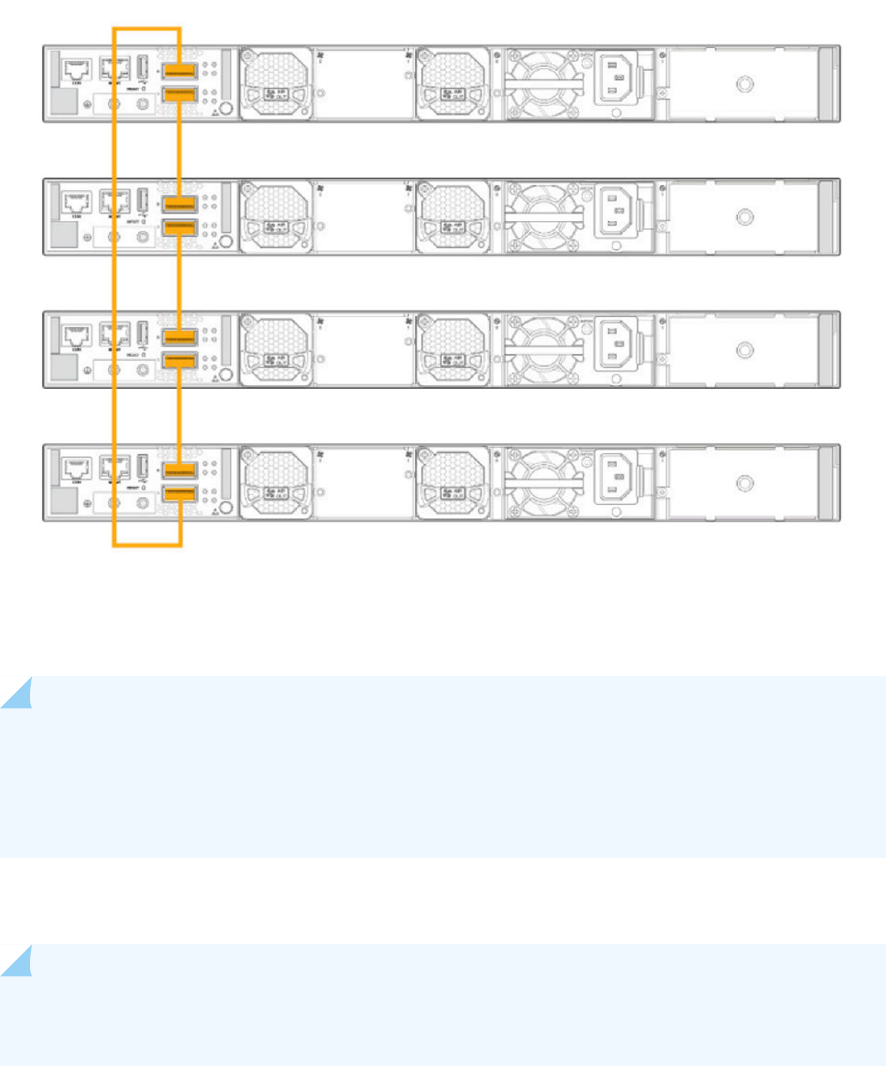
3. Power on the switch that you want to funcon in the primary role.
This member will become FPC0.
NOTE: The order in which you power on devices also determines the member ID. If you
prefer to see the Virtual Chassis members on the Mist portal in the same order as they are
physically stacked, you need to power them on and then connect them to the other exisng
switches in that order.
4. Approximately one minute aer powering on the switch that you selected for the primary role,
power on the switch that you want to funcon in the backup role.
NOTE: In the case of some switch models, you may need to wait for more than one minute as
they take more me to boot up.
This member will become FPC1.
5. Wait for approximately one more minute, and then boot up the rest of the switches that you want to
funcon in the linecard role.
131

NOTE: In the case of some switch models, you may need to wait for more than one minute as
they take more me to boot up.
6. Wait for the MST LED on the primary and backup switches to come up. The LED appears solid on
the primary switch. On the backup switch, the LED stays in a blinking state.
A Virtual Chassis is now physically formed but not preprovisioned.
7. Connect the Virtual Chassis to the Juniper Mist cloud by connecng the uplink port on the primary
switch to the upstream switch.
This step iniates a zero-touch provisioning (ZTP) process on the Virtual Chassis and connects it to
the Juniper Mist cloud.
8. Click Switches >
Switch Name
to go to the Virtual Chassis page (the switch details page) to verify the
details.
The switches appear as a single Virtual Chassis as shown below:
9. Aer Virtual Chassis is connected to the Mist cloud, preprovision it. Preprovisioning allows users to
dene the roles and renumber appropriately. To preprovision the Virtual Chassis, follow the steps
below:
a. On the switch details page, click Modify Virtual Chassis.
The Modify Virtual Chassis page appears.
b. On the Modify Virtual Chassis page, click Preprovision Virtual Chassis. See a sample Modify
Virtual Chassis page below:
132

This step pushes the preprovisioned Virtual Chassis conguraon to the device and overwrites
the old autoprovision Virtual Chassis conguraon in the device. This opon assumes the current
posioning of the members and preprovisions them as is.
NOTE: If you make any changes on the Modify Virtual Chassis page, such as moving the
members around or adding or removing members, the Preprovision Virtual Chassis buon is
disabled and the Update buon is enabled. In this case, click the Update buon to eect the
changes made and Preprovision the Virtual Chassis.
All conguraons are pushed instantly aer you preprovision the Virtual Chassis. The stats could
take up to 15 minutes to appear on the Mist dashboard.
For a detailed procedure on how to modify a Virtual Chassis, see "Manage a Virtual Chassis Using Mist
(Add, Delete, Replace, and Modify Members)" on page 134.
133

Manage a Virtual Chassis Using Mist (Add, Delete,
Replace, and Modify Members)
IN THIS SECTION
Prerequisites | 135
Replace a Member Switch in a Virtual Chassis | 136
Renumber the Virtual Chassis Members | 144
Reassign the Virtual Chassis Member Roles | 146
Delete Virtual Chassis Members | 148
Add a Member Switch to a Virtual Chassis | 149
You can use the Modify Virtual Chassis opon on the switch details page to manage your Virtual
Chassis. The operaons you can perform include renumbering and replacing the Virtual Chassis
members and adding new members to a Virtual Chassis.
The Modify Virtual Chassis workow leverages the pre-provisioned way of Junos conguraon. This
opon is visible for switches that have the conguraon management opon enabled in Mist.
The preprovisioned conguraon species the chassis serial number, member ID, and role for both
member switches in the Virtual Chassis. When a new member router joins the Virtual Chassis, Junos
compares its serial number against the values specied in the preprovisioned conguraon.
Preprovisioning prevents any accidental role assignment to a Roung Engine, or any accidental addion
of a new member to the Virtual Chassis. Role assignments, member ID assignments, and addions or
deleons of members in Virtual Chassis are under the control of a preprovisioned conguraon.
134

NOTE:
• The Modify Virtual Chassis opon is available:
• To Super Users or Network Admins.
• For switches that have their conguraon managed by Mist.
• This workow applies to all the EX Series and QFX Series plaorms that support Virtual
Chassis.
• To delete the FPC0, trash and replace it with an exisng member in the Virtual Chassis. You
cannot add a new member during the deleon of the FPC0.
• The Add Switch dropdown only shows the switches that:
• Share the same major rmware version as the exisng members in the Virtual Chassis.
• Are part of the same site. Models with dedicated Virtual Chassis ports can be in connected
or disconnected state. However, to modify the EX2300, EX4650, or QFX5120 Virtual
Chassis, the members should be in the connected state as these switches don’t have
dedicated Virtual Chassis ports.
• Have conguraon management enabled in Mist.
• Are not currently part of the same or another Virtual Chassis.
• Are of the same model family.
• The Modify Virtual Chassis buon is disabled when the Conguraon Management opon is
disabled for the switch.
• When a Virtual Chassis conguraon is in progress, you cannot make any changes inside the
Modify Virtual Chassis page.
The Modify Virtual Chassis workow leverages the Junos preprovisioning method which congures the
role and serial number of all members in a Virtual Chassis. To learn more about preprovisioning, see
Example: Conguring an EX4200 Virtual Chassis Using a Preprovisioned Conguraon File.
Prerequisites
Before your perform any modicaon to a Virtual Chassis, you must remove all the addional CLI
commands specic to Virtual Chassis (the
virtual-chassis
commands) from the associated device or site
135

template. The addional CLI commands take precedence over other types of conguraons. If a Virtual
Chassis conguraon is detected under the Addional CLI Commands secon, you cannot make any
changes using the Modify Virtual Chassis opon. When you aempt to modify a Virtual Chassis, the
Mist dashboard displays a message to indicate that the Addional CLI commands (if present) need to be
removed and saved.
Replace a Member Switch in a Virtual Chassis
IN THIS SECTION
Replace a Non-FPC0 Member in a Virtual Chassis | 136
Replace the FPC0 Member in a Virtual Chassis | 140
You can replace a disconnected Virtual Chassis member switch with another, by deleng the old
member and adding a new member. For this feature to work, you must ensure the following:
• The new switch is of the same model as the other members in the Virtual Chassis.
• The new switch runs the same Junos version as the other members.
• The new switch is connected to the network.
• The new switch is assigned to the same site as the other members in the Virtual Chassis.
Replace a Non-FPC0 Member in a Virtual Chassis
To replace a non-FPC0 member:
1. Onboard the replacement switch to the Mist cloud and assign it to the same site as the other
members in the Virtual Chassis. To onboard the switch, use the Claim Switch or Adopt Switch
opon on the Inventory page (Organizaon > Inventory). You can also use the Mist AI mobile app to
claim a switch.
During the switch onboarding, remember to enable the conguraon management for the switch
by selecng the Manage conguraon with Mist opon.
For the Adopt Switch workow, the Manage conguraon with Mist opon is available during the
site assignment step. For more informaon on the Adopt Switch workow, see "Onboard a
Browneld Switch" on page 19.
136

For the Claim Switch workow, the Manage conguraon with Mist opon is available on the Claim
Switches and Acvate Subscripon page. For more informaon about the Claim Switch workow,
see Onboard Switches to Mist Cloud.
2. Ensure that the new switch is running the same Junos version as the other members in the Virtual
Chassis. If it is not, upgrade the switch using a USB drive locally or using the Juniper Mist portal.
See "Upgrade Junos OS Soware on Your Switch" on page 96 for more informaon.
3. Power o the new switch (the replacement switch). If you are replacing the FPC0 member, you
must keep the replacement switch powered on all the me.
4. Power o the member to be replaced. Or, remove the Virtual Chassis port (VCP) cables from this
member.
5. Connect the Virtual Chassis cables from the exisng Virtual Chassis members to the new
replacement switch.
6. On the Mist portal, navigate to the switch details page of the Virtual Chassis by clicking Switches >
Switch Name
(the Virtual Chassis name).
7. Wait for the switch details page (the Virtual Chassis page) to display the member switch to be
replaced as oine, as shown below:
8. Click Modify Virtual Chassis.
Because you have removed the VCP connecon from the member switch being replaced, the
Modify Virtual Chassis window displays a broken link for this member switch along with a delete
(trash) icon.
137

9. Delete the member to be replaced by clicking the trash icon.
10. Click Add Switch to add the new replacement member.
11. Renumber the new switch by dragging and dropping it into the appropriate slot. Remember to edit
the MAC address of the backup switch if you are replacing the backup switch.
12. Click Update.
138

13. Power on the replacement switch and wait for Virtual Chassis formaon to be complete.
The Switch Events page displays all the Virtual Chassis update events.
The switch details page displays the updated Virtual Chassis informaon.
139

Replace the FPC0 Member in a Virtual Chassis
The FPC0 is used as the device idener and is used to communicate to the Mist cloud. You cannot
replace the FPC0 with another member in a single operaon. You need to follow a 2-step process -
adding the new replacement switch and then removing the switch to be replaced. You should carry out
the FPC0 replacement operaon in a maintenance window as this operaon can impact the trac to the
clients connected.
1. Click Switches >
Switch Name
to go to the switch details page of the Virtual Chassis to be modied.
2. Click Modify Virtual Chassis.
The Modify Virtual Chassis window appears.
3. On the Modify Virtual Chassis window, click Add Switch and add the replacement switch to the
Virtual Chassis as a new member.
The new switch must be powered on and connected to the cloud.
140

4. Click Update.
141

5. Remove the uplink connecon (in-band or OOB) from FPC0 member (if an uplink is present). Ensure
the connecvity to the Mist cloud is maintained aer the removal of the uplink. If this is the only
uplink, connect it to another member that can provide the uplink connecvity.
6. Power o the FPC0 member to be replaced. Or, remove the VCP cables from it.
7. Remove the DAC cables from the FPC0 being replaced and connect it to the new member in the
same ports.
The Mist cloud adds the new member to the Virtual Chassis.
8. On the Mist portal, navigate to the switch details page of the Virtual Chassis by clicking Switches >
Switch Name
(the Virtual Chassis name).
The switch details page (the Virtual Chassis page) will display the new member switch as part of the
Virtual Chassis.
142

9. On the switch details page, click Modify Virtual Chassis.
Because you have removed the VCP connecon from the FPC0 being replaced, the Modify Virtual
Chassis window displays a broken link against this member switch along with a delete (trash) icon.
10. Delete the member to be replaced by clicking the trash icon.
The Modify Virtual Chassis window displays a message indicang that FPC0 is required.
11. Move the new switch to slot 0 (the FPC0 slot) by dragging and dropping it. Also, update the Backup
eld with the MAC address of the new switch, as shown below:
This step links the new FPC0 device MAC address to the web browser URL and updates the
outbound SSH MAC address eld with the new FPC0 device MAC address.
12. Click Update.
143

Renumber the Virtual Chassis Members
If you prefer to see the Virtual Chassis members on the Mist portal in the same order as they are
physically stacked, you need to power these members on and then connect them to the other exisng
Virtual Chassis switch members in that order.
You can modify the member switches’ order on the Mist portal by renumbering the members. On the
Modify Virtual Chassis window, accessed from the switch details page, you can move around the port
panel of a switch to change the order of the member. The order is incremental. The rst entry is member
0, the second is member 1, and so on. You are required to specify the FPC0.
To renumber the switches in a preprovisioned Virtual Chassis:
1. Click the Switches tab on the le to navigate to the Switches page.
2. Click the Virtual Chassis in which you want to renumber the members.
The switch details page appears.
3. On the switch details page, click Modify Virtual Chassis.
The Modify Virtual Chassis window appears.
4. On the Modify Virtual Chassis screen, drag and drop the port panel of a switch to dierent slots to
change the switch number. The order is incremental. The rst entry is member 0, the second is
member 1, and so on. In the example below, the FPC1 has been renumbered as FPC2 and the FPC2
has been renumbered as FPC1.
144

NOTE:
• You must specify the FPC0 in this conguraon. Within a Virtual Chassis, you cannot
renumber, move around, or delete FPC0 unless it is disconnected. It is the device idener
for connecvity to the Mist cloud.
• Renumbering the members within a Virtual Chassis does not renumber the port
conguraons and port prole assignment. When you renumber a VC, Mist displays the
following warning (as shown in the picture above): "Renumbering of VC members has been
detected. The port conguraons dened under Port Conguraon > Port Prole
145

Assignment will not be modied. Please verify that port conguraons are correct aer
saving these changes."
So, ensure that these changes are taken care of before or aer renumbering the members
in the Virtual Chassis.
5. Aer you have made the changes, click Update.
The members are renumbered.
Reassign the Virtual Chassis Member Roles
A Virtual Chassis conguraon in a Juniper Mist™ network has two switches in the Roung Engine role -
one in the primary Roung Engine role, and the other in the backup Roung Engine role. The remaining
member switches operate in the linecard role. You can change the role of a switch from primary to
backup or backup to linecard or linecard to primary.
To change the role of Virtual Chassis members:
1. Click the Switches tab on the le to navigate to the Switches page.
2. Click the Virtual Chassis in which you want to change the member roles.
The switch details page appears.
3. On the switch details page, click Modify Virtual Chassis.
The Modify Virtual Chassis window appears.
4. On the Modify Virtual Chassis screen, specify a primary switch and a backup switch (oponal) from
the Primary and Backup drop-down list. All the other switches assume a linecard role.
146

5. Aer you have made the changes, click Update.
The member roles are changed.
You will see the updated status about the role change on the switches page on the Mist portal. The role
change will take some me (approximately 15 minutes) to appear on the Mist portal. You can see a
banner message at the top aer every change that you make, as shown below:
147

Delete Virtual Chassis Members
You can delete the member switches from the Virtual Chassis, by clicking the delete (trash) icon on the
Modify Virtual Chassis window. Before deleng any member switch, you must ensure that the switch to
be removed is disconnected from the Virtual Chassis. If the switch is connected, power it o or remove
the VCP connecon from it.
To delete a member switch from Virtual Chassis:
1. Remove the physical VCP connecon of the member switch that you want to delete from the Virtual
Chassis.
2. On the Mist portal, click the Switches tab on the le to navigate to the Switches page.
3. Click the Virtual Chassis from which you want to delete a member switch.
The switch details page appears.
4. On the switch details page, click Modify Virtual Chassis.
The Modify Virtual Chassis window appears. Because you have removed the VCP connecon from
the member switch, the Modify Virtual Chassis window displays a broken link for the member switch
along with a delete icon.
5. Click the delete icon and then click Update.
148

Mist removes the member switch from the Virtual Chassis.
Add a Member Switch to a Virtual Chassis
You can add one or more member switches to a Virtual Chassis from the Modify Virtual Chassis window.
Before adding a new member switch to a Virtual Chassis, ensure the following:
• The new switch is of the same model as the other members in the Virtual Chassis.
149
• The new switch runs the same Junos version as the other members.
• The new switch is connected to the network.
• The new switch is assigned to the same site as the other members in the Virtual Chassis.
To add a new member switch to the Virtual Chassis:
1. Onboard the replacement switch to the Mist cloud and assign it to the same site as the other
members in the Virtual Chassis. To onboard the switch, use the Claim Switch or Adopt Switch opon
on the Inventory page (Organizaon > Inventory). You can also use the Mist AI mobile app to claim a
switch.
During the switch onboarding, remember to enable the conguraon management for the switch by
selecng the Manage conguraon with Mist opon.
For the Adopt Switch workow, the Manage conguraon with Mist opon is available during the
site assignment step. For more informaon on the Adopt Switch workow, see "Onboard a
Browneld Switch" on page 19.
For the Claim Switch workow, the Manage conguraon with Mist opon is available on the Claim
Switches and Acvate Subscripon page. For more informaon about the Claim Switch workow,
see Onboard Switches to Mist Cloud.
2. Ensure that the new switch is running the same Junos version as the other members in the Virtual
Chassis. If it is not, upgrade the switch using a USB drive locally or using the Juniper Mist portal. See
"Upgrade Junos OS Soware on Your Switch" on page 96 for more informaon.
3. On the Mist portal, click the Switches tab on the le to navigate to the Switches page.
4. Click the Virtual Chassis to which you want to add the new member switch.
The switch details page appears.
5. On the switch details page, click Modify Virtual Chassis.
The Modify Virtual Chassis window appears.
6. On the Modify Virtual Chassis window, click Add Switch.
150

7. Specify the VC port ID for the switch, if needed (the port ID conguraon applies to the EX2300,
EX4650, and QFX5120 switches).
8. Click Update.
9. Connect the VCPs as specied on the Modify Virtual Chassis window and wait for 3 to 5 minutes for
virtual chassis to be updated.
151

While the Virtual Chassis is forming, the switches page displays the status as 'VC Forming'.
Aer Mist updates the Virtual Chassis, the switch details page displays the front panel of all the three
Virtual Chassis members.
152


Which Campus Fabric Topology to Choose
IN THIS SECTION
EVPN Mulhoming for Collapsed Core | 154
Campus Fabric Core-Distribuon for Tradional 3-Stage Architecture | 157
Campus Fabric IP Clos for Micro-Segmentaon at Access Layer | 160
Juniper Networks campus fabrics provide a single, standards-based Ethernet VPN-Virtual Extensible
LAN (EVPN-VXLAN) soluon that you can deploy on any campus. You can deploy campus fabrics on a
two-er network with a collapsed core or a campus-wide system that involves mulple buildings with
separate distribuon and core layers.
You can build and manage a campus fabric using the Mist portal. This topic describes the following
campus fabric topologies, all of which Juniper Mist™ supports.
• EVPN Mulhoming
• Campus Fabric Core-Distribuon
• Campus Fabric IP Clos
To help you determine which campus fabric to use, the following secons describe the use cases that
each of the above topologies addresses:
EVPN Mulhoming for Collapsed Core
The Juniper Networks campus fabrics EVPN mulhoming soluon supports a collapsed core
architecture, which is a small to mid-size enterprise networking architecture. In a collapsed core model,
you deploy up to two Ethernet switching plaorms that are interconnected using technologies such as
Virtual Router Redundancy Protocol (VRRP), Hot Standby Router Protocol (HSRP) and mulchassis link
aggregaon group (MC-LAG). The endpoint devices include laptops, access points (APs), printers, and
Internet of Things (IoT) devices. These endpoint devices plug in to the access layer using various
Ethernet speeds, such as 100M, 1G, 2.5G, and 10G. The access layer switching plaorms are
mulhomed to each collapsed core Ethernet switch in the core of the network.
The following image represents the tradional collapsed core deployment model:
154

Figure 4: Collapsed Core Topology
However, the tradional collapsed core deployment model presents the following challenges:
• Its proprietary MC-LAG technology requires a homogeneous vendor approach.
• It lacks horizontal scale. It supports only up to two core devices in a single topology.
• It lacks nave trac isolaon capabilies in the core.
• Not all implementaons support acve-acve load balancing to the access layer.
EVPN Mulhoming addresses these challenges and provides the following advantages:
• Provides standards based EVPN-VXLAN framework.
• Supports horizontal scale up to four core devices.
• Provides trac isolaon capabilies nave to EVPN-VXLAN.
• Provides nave acve-acve load-balancing support to the access layer using Ethernet Switch
Idener-link aggregaon groups (ESI-LAGs).
• Provides standard Link Aggregaon Control Protocol (LACP) at the access layer.
• Migates the need for spanning tree protocol (STP) between the core and access layer.
155
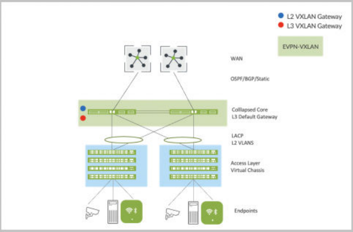
Figure 5: EVPN Mulhoming
Choose EVPN Mulhoming if you want to:
• Retain your investment in the access layer.
• Refresh your legacy hardware that supports collapsed core.
• Scale your deployment beyond two devices in the core.
• Leverage the exisng access layer without introducing any new hardware or soware models.
• Provide nave acve-acve load-balancing support for the access layer through ESI-LAG.
• Migate the need for STP between the core and the access layer.
• Use the standards-based EVPN-VXLAN framework in the core.
The following Juniper plaorms support EVPN Mulhoming:
• Core layer devices: EX9200, EX4400-48F, and EX4400-24X, EX4650, QFX5120, QFX5110,
QFX5700, and QFX5130
• Access layer devices: Third party devices using LACP, Juniper Virtual Chassis, or standalone EX
switches
156

Campus Fabric Core-Distribuon for Tradional 3-Stage Architecture
Enterprise networks that scale past the collapsed core model typically deploy a tradional three-stage
architecture involving the core, distribuon, and access layers. In this case, the core layer provides the
Layer 2 (L2) or Layer 3 (L3) connecvity to all users, printers, APs, and so on. And the core devices
interconnect with the dual WAN routers using standards-based OSPF or BGP technologies.
Figure 6: 3-Stage Core-Distribuon-Access Network
This tradional deployment model faces the following challenges:
• Its proprietary core MC-LAG technology requires a homogeneous vendor approach.
• Only up to two core devices are supported in a single topology.
• Lack of nave trac isolaon capabilies anywhere in this network.
• Requires STP between the distribuon and access layers and potenally between the core and
distribuon layers. This results in sub-opmal use of links.
• Careful planning is required if you need to move the L3 boundary between core and distribuon
layers.
• VLAN extensibility requires deploying VLANs across all links between access switches.
157
The Campus Fabric Core-Distribuon architecture addresses these challenges in the physical layout of a
three-stage model and provides the following advantages:
• Helps in retaining your investment in the access layer. In an enterprise network, your company makes
most of the Ethernet switching hardware investment in the access layer where endpoints terminate.
The endpoint devices (including laptops, APs, printers, and IOT devices) plug in to the access layer.
These devices use various Ethernet speeds, such as 100M, 1G, 2.5G, and 10G.
• Provides a standards-based EVPN-VXLAN framework.
• Supports horizontal scale at the core and distribuon layers, supporng an IP Clos architecture.
• Provides trac isolaon capabilies nave to EVPN-VXLAN.
• Provides nave acve-acve load balancing to the access layer using ESI-LAG.
• Provides standard LACP at the access layer.
• Migates the need for STP between all layers.
• Supports the following topology subtypes:
• Centrally routed bridging (CRB): Targets north-south trac paerns with the L3 boundary or
default gateway shared between all core devices.
• Edge-routed bridging (ERB): Targets east-west trac paerns and IP mulcast with the L3
boundary or the default gateway shared between all distribuon devices.
To know about more benets of Campus Fabric Core-Distribuon deployments, See Benets of Campus
Fabric Core-Distribuon.
158
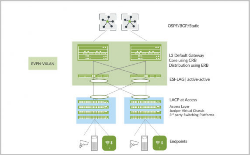
Figure 7: Campus Fabric Core-Distribuon - CRB or ERB
Choose Campus Fabric Core-Distribuon if you want to:
• Retain your investment in the access layer while leveraging the exisng LACP technology.
• Retain your investment in the core and distribuon layers.
• Have an IP Clos architecture between core and distribuon built on standards-based EVPN-VXLAN.
• Have acve-acve load-balancing at all layers, as listed below:
• Equal-cost mulpath (ECMP) between the core and distribuon layers
• ESI-LAG towards the access layer
• Migate the need for STP between all layers.
The following Juniper plaorms support Campus Fabric Core-Distribuon (CRB/ERB):
• Core layer devices: EX4650, EX9200, EX4400-48F, EX4400-24X, QFX5120, QFX5110, QFX5700,
and QFX5130
• Distribuon layer devices: EX4650, EX9200, EX4400-48F, EX4400-24X, QFX5120, QFX5110,
QFX5700, and QFX5130
• Access layer devices: Third party devices using LACP, Juniper Virtual Chassis, or standalone EX
switches
159

Campus Fabric IP Clos for Micro-Segmentaon at Access Layer
Enterprise networks need to accommodate the growing demand for cloud-ready, scalable, and ecient
networks. This demand includes a great number of IoT and mobile devices. This also creates the need for
segmentaon and security. IP Clos architectures help enterprises meet these challenges. An IP Clos
soluon provides increased scalability and segmentaon using a standards-based EVPN-VXLAN
architecture with Group Based Policy (GBP) capacity.
A Campus Fabric IP Clos architecture provides the following advantages:
• Micro-segmentaon at the access layer using standards-based Group Based Policy
• Integraon with third-party network access control (NAC) or RADIUS deployments
• Standards-based EVPN-VXLAN framework across all layers
• Flexibility in scale supporng 3-stage and 5-stage IP Clos deployments
• Trac-isolaon capabilies nave to EVPN-VXLAN
• Nave acve-acve load balancing within campus fabric by ulizing ECMP
• Network opmized for IP mulcast
• Fast convergence between all layers, using a ne-tuned Bidireconal Forwarding Detecon (BFD)
• Oponal Services Block for customers who wish to deploy a lean core layer
• Migated need for STP between all layers
To know about more benets of Campus Fabric IP Clos deployments, see Benets of Campus Fabric IP
Clos.
The following images represents the 3-stage and 5-stage IP Clos deployment.
160

Figure 8: Campus Fabric IP Clos 3 Stage
Figure 9: Campus Fabric IP Clos 5 Stage
The following Juniper Network plaorms support Campus Fabric IP Clos:
• Core layer devices: EX9200, EX4400-48F, EX4400-24X, EX4650, QFX5120, QFX5110, QFX5700,
and QFX5130
• Distribuon layer devices: EX9200, EX4400-48F, EX4400-24X, EX4650, QFX5120, QFX5110,
QFX5700, and QFX5130
161

• Access layer devices: EX4100, EX4300-MP, and EX4400
• Services Block devices: QFX5120, EX4650, EX4400-24X, EX4400, QFX5130, QFX5170, EX9200,
and QFX10k
How to Migrate a Tradional Enterprise Network to
a Juniper Campus Fabric
IN THIS SECTION
Build Campus Fabric in Parallel to the Exisng Network | 164
Interconnect the Campus Fabric to the Exisng Network | 164
Migrate VLANs to the Campus Fabric | 165
Migrate the Crical Infrastructure to the Services Block | 166
Migrate WAN Router(s) to the Services Block | 167
Decommission the Exisng Enterprise Network | 167
This document details a strategy to migrate a tradional enterprise network-based architecture to a
Juniper Campus Fabric EVPN-VXLAN architecture.
Juniper’s campus fabric leverages EVPN VXLAN as the underlying technology for small, mid, and large
enterprise deployments. You can build and manage campus fabric by using Mist’s Wired Assurance
Cloud-ready framework. For addional informaon on Juniper’s Campus Fabric, see Juniper Mist Wired
Assurance datasheet.
Video: Three Step Campus Fabric
This migraon strategy focuses on an enterprise network consisng of the tradional 3-stage
architecture of access, distribuon, and core. In this example, core provides layer 3 connecvity to all
users, printers, access points (APs), and so on. And the core layer interconnects with dual WAN routers
using standards based OSPF or BGP technologies.
162

Figure 10: Tradional Enterprise Network
At a high-level, migraon from a tradional enterprise network to a Juniper campus fabric architecture
involves the following steps:
1. Build a campus fabric architecture in parallel to the exisng enterprise network.
2. Interconnect the campus fabric to the exisng network using a services block.
3. Migrate VLANs one by one to the campus fabric.
4. Migrate the crical infrastructure such as DHCP server and RADIUS to the services block.
163

5. Migrate WAN router(s) to the services block.
6. Decommission the exisng enterprise network once all the connecvity is veried.
Build Campus Fabric in Parallel to the Exisng Network
As the rst step, build a campus fabric by using Mist’s Wired Assurance framework. This step allows you
to deploy an operaonal campus fabric in parallel to the exisng network. In this example, we choose
the campus fabric IP Clos architecture because the customer has a micro-segmentaon strategy
deployed at the access layer. The customer has chosen the following Juniper equipment to be deployed
within the Campus Fabric IP Clos architecture:
• QFX5120 switches (core layer)
• QFX5120 switches (distribuon layer)
• EX4100 and EX4400 switches in Virtual Chassis mode (access layer)
• QFX5120 switches (services block)
See also: "Congure Campus Fabric IP Clos" on page 185.
Figure 11: Co-existence of Campus Fabric with Enterprise Network
Interconnect the Campus Fabric to the Exisng Network
You can use the services block to interconnect the campus fabric with the enterprise network. You can
do this by using ESI-LAG technologies at layer 2, or the standard roung protocols such as BGP or OSPF
164

if layer 3 connecvity is required. In this case, we interconnect the services block to the core enterprise
using OSPF.
Figure 12: Services Block Interconnects with the Core Using OSPF
The loopback reachability between the two networks should be established through the services block.
For example, the campus fabric build assigns loopback addresses to each device. By default, these
addresses are part of the same subnet. OSPF should exchange these addresses with routable prexes
sent by the core layer through the services block. The end-user should verify reachability between these
prexes before moving to the next step.
Migrate VLANs to the Campus Fabric
This process requires you to remove each VLAN and associated layer 3 interface from the enterprise
network. You need to migrate all devices within the VLAN to the campus fabric and then have the end-
user verify full connecvity from the devices on the migrated VLAN to the applicaons and devices on
the enterprise network. The following summarizes this step:
• Migrate VLANs to campus fabric by disabling or removing the layer 3 subnet from the current
network.
• Users and devices migrate to the access layer of the campus fabric.
• Layer 3 interconnect provides reachability on a VLAN-by-VLAN basis.
• Users and devices must validate all applicaon reachability before moving to the next VLAN.
165

Figure 13: All VLANs and Access Devices Migrated to the Campus Fabric
Migrate the Crical Infrastructure to the Services Block
Juniper recommends dual homing of each crical infrastructure service (such as DHCP server and
RADIUS) to the services block. You can do this by using ESI-LAG technologies at layer 2, or the standard
roung protocols such as BGP or OSPF if layer 3 connecvity is required. Accessibility of crical
infrastructure services within the campus fabric and from the enterprise network should be veried
before moving to the next step.
Figure 14: Crical Infrastructure Migraon to the Services Block
166

Migrate WAN Router(s) to the Services Block
Mist lets you connect WAN router(s) to the services block using BGP or OSFP. Aer WAN routers are
connected to the service block, verify the accessibility of WAN services to and from the campus fabric
before moving to the next step.
Figure 15: WAN Routers Migraon to the Services Block
Decommission the Exisng Enterprise Network
We recommend that you keep the enterprise network up and operaonal for at least one week aer all
services and applicaons are reachable without issue to and from the campus fabric. Aer that,
decommission the exisng enterprise network.
Congure Campus Fabric EVPN Mulhoming
The Juniper Networks campus fabrics EVPN mulhoming soluon supports a collapsed core
architecture. This architecture merges the core and distribuon layers into a single switch. Merging
these layers into a single switch turns the tradional three-er hierarchical network into a two-ered
network. This architecture also eliminates the need for STP across campus networks by providing
mulhoming capabilies from the access layer to the core layer.
For a detailed conguraon example, see Campus Fabric EVPN Mulhoming Workow.
167

To congure campus fabric EVPN mulhoming:
1. Click Organizaon > Campus Fabric.
2. From the site drop-down list beside the page heading, select the site where you want to build the
campus fabric.
The topology type EVPN Mulhoming is available only for the site-specic campus fabric. You
cannot build it for an enre organizaon.
3. Click whichever opon is relevant. Click the:
• Congure Campus Fabric buon (displayed if the site doesn't have a campus fabric conguraon
associated with it).
• Create Campus Fabric buon (displayed if the site already has at least one campus fabric
conguraon associated with it).
The Topology tab is displayed.
4. Select the topology type EVPN Mulhoming.
168

5. Congure the remaining sengs on the Topology tab, as described below:
NOTE: We recommend that you use the default sengs on this screen unless they conict
with any networks aached to the campus fabric. The point-to-point links between each
layer ulize /31 addressing to conserve addresses.
a. In the CONFIGURATION secon, congure the following:
• Topology Name—Enter a name for the topology.
• Virtual Gateway v4 MAC Address—If you enable it, Mist provides a unique MAC address to
each Layer 3 (L3) virtual gateway (per network). This seng is disabled by default.
b. (If you choose not to use the default sengs) In the OVERLAY SETTINGS secon, enter the
following:
• BGP Local AS—Represents the starng point of private BGP AS numbers that Mist allocates
to each device automacally. You can use any private BGP AS number range that suits your
169

deployment. Mist provisions the roung policy so that only the loopback IP addresses are
exchanged in the underlay of the fabric.
c. (If you choose not to use the default sengs) In the UNDERLAY SETTINGS secon, congure
the following:
• AS Base—The AS base number. The default is 65001.
• Underlay—Select an internet protocol for the underlay. Opons are IPv4 and IPv6.
• Subnet—The range of IP addresses that Mist uses for point-to-point links between devices.
You can use a range that suits your deployment. Mist breaks this subnet into /31 subnet
addressing per link. You can modify this number to suit the specic deployment scale. For
example, a /24 network would provide up to 128 point-to-point /31 subnets.
• IPv6 Loopback Interface—Specify an IPv6 loopback interface subnet, which is used to
autocongure IPv6 loopback interface on each device in the fabric.
• Auto Router ID Subnet/Loopback Interface—Mist uses this subnet to automacally assign a
router ID to each device in the fabric (including access devices irrespecve of whether they
are congured with EVPN or not). Router IDs are loopback interfaces (lo0.0) used for overlay
peering between devices. For new topologies, this eld auto-populates a default subnet
value (172.16.254.0/23), which you can modify. When you edit an exisng topology, this
eld doesn’t populate any default value. The router ID is used as an idener when
deploying roung protocols such as BGP. Aer you add the switch to the collapsed core
layer, click the switch icon to see the associated router ID.
You can overwrite the automacally assigned router ID by manually conguring a loopback
interface in the Router ID eld on the Roung le on the switch conguraon page (Switches
>
Switch Name
). However, if you modify the campus fabric conguraon aerwards, Mist
performs the automac assignment of the router ID again, replacing the manually congured
loopback interface.
6. Click Connue to go to the Nodes tab, where you can select devices that form part of the campus
fabric deployment.
7. Add switches to the collapsed core layer and access layer.
170
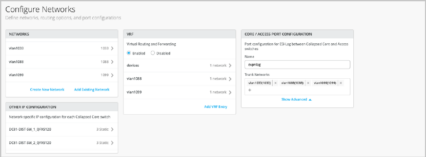
We recommend that you validate the presence of each device in the switch inventory before
creang the campus fabric.
To add switches:
a. Click Select Switches.
b. Choose the switches that you want to add to the campus fabric.
c. Click Select.
8. Aer selecng the switches, click Connue to go to the Network Sengs tab, where you can
congure the networks.
9. Congure the network sengs, as described below:
a. On the NETWORKS le, add networks or VLANs to the conguraon. You can either create a
new network or import the network from the switch template dened on the Organizaon >
Switch templates page.
To add a new VLAN, click Create New Network and congure the VLANs. The sengs include a
name, VLAN ID, and a subnet.
To import VLANs from the template:
i. Click Add Exisng Network.
ii. Select a switch template from the Template drop-down list to view the VLANs available in
that template.
iii. Select the required VLAN from the displayed list, and click the ✓ mark.
VLANs are mapped to Virtual Network Ideners (VNIs). You can oponally map VLANs to
virtual roung and forwarding (VRF) instances to logically separate the trac.
b. Review the sengs in the OTHER IP CONFIGURATION le. This secon populates the sengs
automacally aer you specify the networks in the NETWORKS secon.
171
c. Oponally, congure VRF instances on the VRF le. By default, Mist places all VLANs in the
default VRF. The VRF opon allows you to group common VLANs in the same VRF or separate
VRFs depending on trac isolaon requirements. All VLANs within each VRF have full
connecvity with each other and with other external networking resources. A common use case
is isolaon of guest wireless trac from most enterprise domains except Internet connecvity.
By default, campus fabric provides complete isolaon between VRFs, forcing inter-VRF
communicaons to traverse a rewall. If you require inter-VRF communicaon, you need to
include extra routes to the VRF. The extra route could be a default route that instructs the
campus fabric to use an external router. It could also be a rewall for further security inspecon
or roung capabilies.
To create a VRF:
i. Click Add VRF Instance and specify the sengs. The sengs include a name for the VRF
and the networks to be associated with the VRF.
ii. To add extra routes, click the Add Extra Routes link on the New VRF Instance page, and
specify the route.
d. On the CORE / ACCESS PORT CONFIGURATION le, complete the port conguraon for ESI-
LAG between the collapsed core and access switches. The sengs include a name and other
port conguraon elements. By default, this conguraon includes the networks added on the
NETWORKS le on the same page. If you want to remove or modify the sengs, click Show
Advanced and congure the sengs. Use the ps on the screen to congure the port prole
sengs.
e. On the DHCP RELAY le, congure the DHCP relay sengs. You have the following opons:
• Enabled—Congures DHCP relay on all the IRB-enabled devices in campus fabric. This opon
allows you to enable DHCP Relay on networks that you selected. The network will be
populated inside the DHCP Relay le as long as it is listed on the Networks tab on the same
page.
• Disabled—Disable DHCP relay on the devices in campus fabric. When you select this opon,
the DHCP relay is disabled on all the IRB-enabled devices. You should carefully select this
opon as this will remove the locally dened DHCP Relay on the Switch Detail page.
• None—This opon is automacally selected when the campus fabric topology has a mix of
devices in terms of the DHCP relay conguraon; that is, some devices have the DHCP relay
enabled, some have it disabled, and some do not have it dened. This opon will be visible
for all Campus Fabric topologies that have DHCP Relay locally dened on individual switches.
If you want to remove all locally dened DHCP Relay networks, select Enabled and then choose
Remove all exisng device level DHCP Networks. You can simplify your DHCP Relay
deployment by centralizing any conguraon change from the campus fabric workow.
172

If you enable DHCP relay in a campus fabric conguraon, it is enabled on all the IRB-dened
devices in the fabric and disabled on the rest of the devices. For example, in EVPN Mulhoming
topologies, DHCP relay is enabled on collapsed core devices and disabled on the rest.
10. Click Connue to go to the Ports tab, where you can congure the ports and create a connecon
between the core, distribuon, and access layer switches.
11. Congure the switch ports in the collapsed core layer as follows:
a. Select a switch in the Collapsed Core secon to open the switch port panel.
b. From the port panel of the switch, select a port that you want to congure.
c. Specify a port type (for example, ge or xe).
d. Select:
• Link to Collapsed Core to connect the port to a core switch.
• Link to Access to connect the port to an access switch.
e. Select the core or access switch (based on the selecon in the previous step) on which the link
should terminate. You need to congure all the ports that need to be part of the campus fabric.
To congure the switch ports in the access layer:
a. Select a switch in the Access secon to open the switch port panel.
b. From the port panel of the switch, select a port that you want to congure.
c.
Specify a port type (for example, ge or xe).
173

In case the access layer uses a Virtual Chassis (VC), you can congure ports on the Primary and
Backup tabs.
For the access switches, select only those interfaces that should be used to interconnect with the
distribuon switch. The system bundles all interfaces into a single Ethernet bundle through the AE
index opon. You can specify an AE index value for the access devices.
If you want to view the conguraon and status informaon of a specic port, hover over the
numbered box represenng that port in the port panel UI.
12. Click Connue to go to the Conrmaon tab.
13. Click each switch icon to view and verify the conguraon.
14. Aer verifying the conguraon, click Apply Changes > Conrm.
This step saves the campus fabric conguraon to the Mist cloud and applies it to the switches. If
the switches are oine, the conguraon will be applied to them when they come online next me.
A switch might take up to 10 minutes to complete the conguraon.
15. Click Close Campus Fabric Conguraon.
Aer Mist builds the campus fabric, or while it is building the fabric, you can download the
connecon table. The connecon table represents the physical layout of the campus fabric. You can
use this table to validate all switch interconnects for the devices parcipang in the physical
campus fabric build. Click Connecon Table to download it (.csv format).
174

16. Verify the campus fabric conguraon. To verify, follow the steps listed in the Vericaon secon in
Campus Fabric EVPN Mulhoming Workow.
Video: Deployment of Campus Fabric EVPN Mulhoming With Wired Assurance
Congure Campus Fabric Core-Distribuon
Juniper Networks campus fabrics provide a single, standards-based EVPN-VXLAN soluon that you can
deploy on any campus. The campus fabric core-distribuon soluon extends the EVPN fabric to connect
VLANs across mulple buildings. This network architecture includes the core and distribuon layers that
integrate with the access switching layer through the standard LACP.
For more background informaon about campus fabric core-distribuon architectures, see the following
documents:
• Campus Fabric Core Distribuon CRB (JVD)
• Campus Fabric Core-Distribuon ERB (JVD)
To congure campus fabric core-distribuon:
1. Click Organizaon > Campus Fabric.
2. If you want to create the campus fabric for a site, select the site from the drop-down list beside the
page header. If you want to create the campus fabric for the enre organizaon, select Enre Org
from the drop-down list.
175

You can use an organizaon-level campus fabric topology to build a campus-wide architecture with
mulple buildings. Otherwise, build a site-specic campus fabric with a single set of core,
distribuon, and access switches.
3. Click whichever opon is relevant. Click the:
• Congure Campus Fabric buon (displayed if the site doesn't have a campus fabric conguraon
associated with it).
• Create Campus Fabric buon (displayed if the site already has at least one campus fabric
conguraon associated with it).
The Topology tab is displayed.
4. Select the topology type Campus Fabric Core-Distribuon.
176

5. Congure the topology name and other sengs on the Topology tab, as described below:
NOTE: We recommend that you use the default sengs on this screen unless they conict
with any networks aached to the campus fabric. The point-to-point links between each
layer ulize /31 addressing to conserve addresses.
a. In the CONFIGURATION secon, enter the following:
• Topology Name—Enter a name for the topology.
177
• Topology Sub-type—Choose one of the following opons:
• CRB—In this model, the Layer 3 (L3) VXLAN gateway funcon is congured only on the
core devices. This is accomplished by dening integrated roung and bridging (IRB)
interfaces on the core devices to provide L3 roung services. This opon uses virtual
gateway addressing for all devices parcipang in the L3 subnet. Enabling this opon
congures core switches with a shared IP address for each L3 subnet. This address is
shared between both the core switches and is used as the default gateway address for all
devices within the VLAN. In addion, Mist assigns each core device with a unique IP
address.
• Virtual Gateway v4 MAC Address—Available only if you have selected CRB. If you
enable it, Mist provides a unique MAC address to each L3 IRB interface (per network).
• ERB—In this model, the L2 and L3 VXLAN gateway funcons are congured on the
distribuon devices. In this case the IRB interfaces are dened on the distribuon devices
to provide L3 roung services. This opon uses anycast addressing for all devices
parcipang in the L3 subnet. In this case, the distribuon switches are congured with
the same IP address for each L3 subnet.
b. (If you choose not to use the default sengs) In the TOPOLOGY SETTINGS secon, enter the
following:
• BGP Local AS—Represents the starng point of private BGP AS numbers that Mist allocates
to each device automacally. You can use any private BGP AS number range that suits your
deployment. Mist provisions the roung policy so that only the loopback IP addresses are
exchanged in the underlay of the fabric.
• Underlay—Select an internet protocol for the underlay. Opons are IPv4 and IPv6. Only to
ERB topologies support IPv6. You get the opon to select IPv6 only if you selected ERB as
Topology Sub-type.
• Subnet— The range of IP addresses that Mist uses for point-to-point links between devices.
You can use a range that suits your deployment. Mist breaks this subnet into /31 subnet
addressing per link. You can modify this number to suit the specic deployment scale. For
example, a /24 network would provide up to 128 point-to-point /31 subnets.
• IPv6 Loopback Interface—Specify an IPv6 loopback interface subnet, which is used to
autocongure IPv6 loopback interface on each device in the fabric.
• IPv4 Auto Router ID Subnet / Loopback Interface—Mist uses this subnet to automacally
assign a router ID to each device in the fabric (including access devices irrespecve of
whether they are congured with EVPN or not). Router IDs are loopback interfaces (lo0.0)
used for overlay peering between devices. For new topologies, this eld auto-populates a
default subnet value (172.16.254.0/23), which you can modify. When you edit an exisng
178

topology, this eld doesn’t populate any default value. The router ID is used as an idener
when deploying roung protocols such as BGP.
You can overwrite the automacally assigned router ID by manually conguring a loopback
interface in the Router ID eld on the Roung le on the switch conguraon page (Switches
>
Switch Name
). However, if you modify the campus fabric conguraon aerwards, Mist
performs the automac assignment of the router ID again, replacing the manually congured
loopback interface.
• Loopback per-VRF subnet—Mist uses this subnet to automacally congure loopback
interfaces (lo0.x) per the virtual roung and forwarding (VRF) instance that is used for
services such as DHCP relay. For new topologies, this eld auto-populates a default subnet
value (172.16.192.0/24), which you can modify. This eld supports a /19 or smaller subnet
(for example, /24). When you edit an exisng topology, this eld doesn’t populate any
default value.
6. Click Connue to go to the Nodes tab, where you can select devices that form part of the campus
fabric deployment.
7. Add switches to the Core, Distribuon, and Access layer secons.
To add switches:
a. Click Select Switches in the secon to which you want to add switches.
179

b. Choose the switches that you want to add to the campus fabric.
c. Click Select.
We recommend that you validate the presence of each device in the switch inventory before
creang the campus fabric.
By default, Mist congures the core switches to funcon as border nodes that run the service block
funconality. In a campus fabric topology, border nodes interconnect external devices such as
rewalls, routers, or crical devices. External services or devices (for example, DHCP and RADIUS
servers) connect to the campus fabric through border nodes. If you want to ooad this task from
the core switches and use dedicated switches as border nodes, clear the Use Core as border
checkbox on the upper le of the page. You can then add up to two switches as dedicated border
nodes.
Also, Mist provides pods for improved scalability. Your access and distribuon devices are grouped
into pods. A pod could represent a building. For example, you can create a pod for each of the
buildings in your site and create connecons between the access and the distribuon devices in
that pod. You do not have to connect the same set of access devices to the distribuon devices
across mulple buildings. You can create mulple pods by clicking +Add Nodes.
8. Aer selecng the switches, click Connue to go to the Network Sengs tab, where you can
congure the networks.
9. Congure the network sengs, as described below:
a. On the NETWORKS le, add networks or VLANs to the conguraon. You can either create a
new network or import the network from the switch template dened on the Organizaon >
Switch templates page.
To add a new VLAN, click Create New Network and congure the VLANs. The sengs include a
name, VLAN ID, and a subnet.
To import VLANs from the template:
i. Click Add Exisng Network.
180
ii. Select a switch template from the Template drop-down list to view the VLANs available in
that template.
iii. Select the required VLAN from the displayed list, and click the ✓ mark.
VLANs are mapped to Virtual Network Ideners (VNIs). You can oponally map the VLANs to
VRF instances to logically separate the trac.
b. Review the sengs on the OTHER IP CONFIGURATION le, which populates the informaon
automacally aer you specify the networks in the NETWORKS secon.
Mist provides automac IP addressing of IRBs for each of the VLANs. Then, the port prole
associates the VLAN with the specied ports.
c. Oponally, congure VRF instances on the VRF le. By default, Mist places all VLANs in the
default VRF. The VRF opon allows you to group common VLANs into the same VRF or
separate VRFs depending on trac isolaon requirements. All VLANs within each VRF have full
connecvity with each other and with other external networking resources. A common use case
is the isolaon of guest wireless trac from most enterprise domains, except Internet
connecvity. By default, a campus fabric provides complete isolaon between VRFs, forcing
inter-VRF communicaons to traverse a rewall. If you require inter-VRF communicaon, you
need to include extra routes to the VRF. The extra route could be a default route that instructs
the campus fabric to use an external router. It could also be a rewall for further security
inspecon or roung capabilies.
To create a VRF:
i. Click Add VRF Instance and specify the sengs. The sengs include a name for the VRF
and the networks to be associated with the VRF.
ii. To add extra routes, click the Add Extra Routes link on the New VRF Instance page and
specify the route.
d. On the DISTRIBUTION / ACCESS PORT CONFIGURATION le, complete the port
conguraon for ESI-LAG between the collapsed core and access switches. The sengs include
a name and other port conguraon elements. By default, this conguraon includes the
networks added on the NETWORKS le on the same page. If you want to remove or modify the
sengs, click Show Advanced and congure the sengs. Use the ps on the screen to congure
the port prole sengs.
e. On the DHCP RELAY le, congure the DHCP relay sengs. You have the following opons:
• Enabled—Congures DHCP relay on all the IRB-enabled devices in campus fabric. This opon
allows you to enable DHCP Relay on networks that you selected. The network will be
populated inside the DHCP Relay le as long as it is listed on the Networks tab on the same
page.
181

• Disabled—Disable DHCP relay on the devices in campus fabric. When you select this opon,
the DHCP relay is disabled on all the IRB-enabled devices. You should carefully select this
opon as this will remove the locally dened DHCP Relay on the Switch Detail page.
• None—This opon is automacally selected when the campus fabric topology has a mix of
devices in terms of the DHCP relay conguraon; that is, some devices have the DHCP relay
enabled, some have it disabled, and some do not have it dened. This opon will be visible
for all Campus Fabric topologies that have DHCP Relay locally dened on individual switches.
If you want to remove all locally dened DHCP Relay networks, select Enabled and then choose
Remove all exisng device level DHCP Networks. You can simplify your DHCP Relay
deployment by centralizing any conguraon change from the campus fabric workow.
If you enable DHCP relay in a campus fabric conguraon, it is enabled on all the IRB-dened
devices in the fabric and disabled on the rest of the devices. For example, in Campus Fabric
Core-Distribuon (CRB) topologies, DHCP relay is enabled on core devices and disabled on the
rest. Similarly, in Campus Fabric Core-Distribuon (ERB), DHCP is enabled on distribuon
devices and disabled on the rest.
10. Click Connue to go to the Ports tab, where you can congure the ports and create a connecon
between the core, distribuon, and access layer switches.
11. Congure the switch ports in the core layer as described below:
a. Select a switch in the Core secon to open the switch port panel.
b. From the port panel of the core switch, select a port that you want to congure.
c. Specify a port type (for example, ge or xe).
d. Choose the distribuon switch on which the link should terminate. You need to congure all the
ports that need to be part of the campus fabric.
182

To congure switch ports in the distribuon layer:
a. Select a switch in the Distribuon secon to open the switch port panel.
b. From the port panel of the switch, select a port that you want to congure.
c. Specify a port type (for example, ge or xe).
d. Select:
• Link to Core to connect the port to a core switch.
• Link to Access to connect the port to an access switch.
e. Select the core or access switch (based on the selecon in the previous step) on which the link
should terminate. You need to congure all the ports that need to be part of the campus fabric.
To congure the switch ports in the access layer:
a. Select a switch in the Access secon to open the switch port panel.
b. From the port panel of the switch, select a port that you want to congure.
c.
Specify a port type (for example, ge or xe).
In case the access layer uses a Virtual Chassis (VC), you can congure ports on the Primary and
Backup tabs.
For the access switches, select only those interfaces that should be used to interconnect with the
distribuon switch. The system bundles all interfaces into a single Ethernet bundle through the AE
index opon. You can specify an AE index value for the access devices.
183

If you want to view the conguraon and status informaon of a specic port, hover over the
numbered box represenng that port in the port panel UI.
12. Click Connue to go to the Conrmaon tab.
13. Click each switch icon to view and verify the conguraon.
14. Aer verifying the conguraon, click Apply Changes > Conrm.
This step saves the campus fabric conguraon to the Mist cloud and applies it to the switches. If
the switches are oine, the conguraon will be applied to them when they come online next me.
A switch might take up to 10 minutes to complete the conguraon.
15. Click Close Campus Fabric Conguraon.
Aer Mist builds the campus fabric, or while it is building the fabric, you can download the
connecon table. The connecon table represents the physical layout of the campus fabric. You can
use this table to validate all switch interconnects for the devices parcipang in the physical
campus fabric build. Click Connecon Table to download it (.csv format).
184

16. Verify the campus fabric conguraon. To verify, follow the steps listed in the Vericaon secon
of Campus Fabric Core Distribuon CRB (JVD) and Campus Fabric Core-Distribuon ERB (JVD).
For a demo, watch the following video:
Video: Deployment of Campus Fabric Core Distribuon
Video:
Congure Campus Fabric IP Clos
Juniper Networks campus fabrics provide a single, standards-based EVPN-VXLAN soluon that you can
deploy on any campus.
The campus fabric IP Clos architecture pushes VXLAN L2 gateway funconality to the access layer. This
model is also called end-to-end, given that VXLAN tunnels terminate at the access layer.
The campus fabric IP Clos architecture supports Group Based Policies (GBPs) that enable you to achieve
micro segmentaon in the network. The GBP opon gives you a praccal way to create network access
policies that are independent of the underlying network topology. In a GBP, you match a user group tag
to a resource group tag to provide the specied users access to the specied resources. See "Create a
Switch Conguraon Template" on page 23 to learn how to congure GBP on switches.
185

In a campus fabric IP Clos architecture, Mist provisions layer 3 (L3) integrated roung and bridging (IRB)
interfaces on the access layer. All the access switches are congured with the same IP address for each
L3 subnet. The end users terminang on the access layer have the default gateway set to the IRB
address shared by all access layer devices. This deployment model ulizes anycast addressing for all
devices parcipang in the L3 subnet. This deployment model provides a smaller blast radius for
broadcast trac and is ideal for east-west trac paerns and IP Mulcast environments.
For more detailed informaon about IP Clos architecture and its deployment, see Campus Fabric IP Clos
Using Mist Wired Assurance—Juniper Validated Design (JVD).
To congure campus fabric IP Clos:
1. Click Organizaon > Campus Fabric.
2. If you want to create the campus fabric for a site, select the site from the drop-down list beside the
page heading. If you want to create the campus fabric for the enre organizaon, select Enre Org
from the drop-down list.
You can use an organizaon-level campus fabric topology to build a campus-wide architecture with
mulple buildings. Otherwise, build a site-specic campus fabric with a single set of core,
distribuon, and access switches.
3. Click whichever opon is relevant. Click the:
• Congure Campus Fabric buon (displayed if the site doesn't have a campus fabric conguraon
associated with it).
• Create Campus Fabric buon (displayed if the site already has at least one campus fabric
conguraon associated with it).
The Topology tab is displayed.
4. Select the topology type Campus Fabric IP Clos.
186

5. Congure the topology name and other sengs on the Topology tab, as described below:
NOTE: We recommend that you use the default sengs on this screen unless they conict
with any networks aached to the campus fabric. The point-to-point links between each
layer ulize /31 addressing to conserve addresses.
a. In the CONFIGURATION secon, enter the following:
• Topology Name—Enter a name for the topology.
187
b. (If you don't want to use the default sengs) In the TOPOLOGY SETTINGS secon, enter the
following:
• BGP Local AS—Represents the starng point of private BGP AS numbers that are
automacally allocated to each device. You can use any private BGP AS number range that
suits your deployment. Mist provisions the roung policy so that only the loopback IP
addresses are exchanged in the underlay of the fabric.
• Underlay—Select an internet protocol for the underlay. Opons are IPv4 and IPv6.
• Subnet— The range of IP addresses that Mist uses for point-to-point links between devices.
You can use a range that suits your deployment. Mist breaks this subnet into /31 subnet
addressing per link. You can modify this number to suit the specic deployment scale. For
example, a /24 network would provide up to 128 point-to-point /31 subnets.
• IPv6 Loopback Interface—Specify an IPv6 loopback interface subnet, which is used to
autocongure IPv6 loopback interface on each device in the fabric.
• IPv4 Auto Router ID Subnet / Loopback Interface—Mist uses this subnet to automacally
assign a router ID to each device in the fabric (including access devices irrespecve of
whether they are congured with EVPN or not). Router IDs are loopback interfaces (lo0.0)
used for overlay peering between devices. For new topologies, this eld auto-populates a
default subnet value (172.16.254.0/23), which you can modify. When you edit an exisng
topology, this eld doesn’t populate a default value. The router ID is used as an idener
when deploying roung protocols such as BGP.
You can overwrite the automacally assigned router ID by manually conguring a loopback
interface in the Router ID eld on the Roung le on the switch conguraon page (Switches
>
Switch Name
). However, if you modify the campus fabric conguraon aerwards, Mist
performs the automac assignment of the router ID again, replacing the manually congured
loopback interface.
• Loopback per-VRF subnet—Mist uses this subnet to automacally congure loopback
interfaces (lo0.x) per virtual roung and forwarding (VRF) instance that is used for services
such as DHCP relay. For new topologies, this eld auto-populates a default subnet value
(172.16.192.0/24), which you can modify. This eld supports a /19 or smaller subnet (for
example, /24). When you edit an exisng topology, this eld doesn’t populate a default value.
6. Click Connue to go to the Nodes tab, where you can select devices that form part of the campus
fabric IP Clos deployment.
188

7. Add switches to the Core, Distribuon, and Access layer secons.
To add the switches:
a. Click Select Switches in the secon to which you want to add switches.
b. Select the switches that you want to add to the campus fabric.
c. Click Select.
We recommend that you validate the presence of each device in the switch inventory before
creang the campus fabric.
By default, Mist congures the core switches to funcon as border nodes that run the service block
funconality. In a campus fabric topology, border nodes interconnect external devices such as
rewalls, routers, or crical devices. External services or devices (for example, DHCP and RADIUS
servers) connect to the campus fabric through border nodes. If you want to ooad this task from
the core switches and use dedicated switches as border nodes, clear the Use Core as border
checkbox on the upper le of the page. You can then add up to two switches as dedicated border
nodes. The minimum number of dedicated border nodes required is one.
Also, Mist provides pods for improved scalability. Your access and distribuon devices are grouped
into pods. A pod could represent a building. For example, you can create a pod for each of the
189

buildings in your site and create connecons between the access and the distribuon devices in
that pod. You do not have to connect the same set of access devices to the distribuon devices
across mulple buildings. You can create mulple pods by clicking +Add Nodes.
8. Aer selecng the switches, click Connue to go to the Network Sengs tab, where you can
congure the networks.
9. Congure the network sengs, as described below.
a. From the NETWORKS le, add networks or VLANs to the conguraon. You can either create a
new network or import the network from the switch template dened in the Organizaon >
Switch templates page.
To add a new VLAN, click Create New Network and congure the VLANs. The sengs include a
name, VLAN ID, and a subnet.
To import VLANs from the template:
i. Click Add Exisng Network.
ii. Select a switch template from the Template drop-down list to view the VLANs available in
that template.
iii. Select the required VLAN from the displayed list, and click the ✓ mark.
VLANs are mapped to Virtual Network Ideners (VNIs). You can oponally map the VLANs to
VRF instances to logically separate the trac.
b. Review the sengs on the OTHER IP CONFIGURATION le. This le populates the sengs
automacally aer you specify the networks in the NETWORKS secon.
Mist provides automac IP addressing of IRB for each of the VLANs. Then, the port prole
associates the VLAN with the specied ports.
c. Oponally, congure VRF instances in the VRF le. By default, Mist places all VLANs in the
default VRF. The VRF opon allows you to group common VLANs into the same VRF or
separate VRFs depending on trac isolaon requirements. All VLANs within each VRF have full
190
connecvity with each other and with other external networking resources. A common use case
is the isolaon of guest wireless trac from most enterprise domains except Internet
connecvity. By default, a campus fabric provides complete isolaon between VRFs, forcing
inter-VRF communicaons to traverse a rewall. If you require inter-VRF communicaon, you
need to include extra routes to the VRF. The extra route could be a default route that instructs
the campus fabric to use an external router. It could also be a rewall for further security
inspecon or roung capabilies.
To create a VRF:
i. Click Add VRF Instance and specify the sengs. The sengs include a name for the VRF
and the networks to be associated with the VRF.
ii. To add extra routes, click the Add Extra Routes link on the New VRF Instance page and
specify the route.
d. On the DHCP RELAY le, congure the DHCP relay sengs. You have the following opons:
• Enabled—Congures DHCP relay on all the IRB-enabled devices in campus fabric. This opon
allows you to enable DHCP Relay on networks that you selected. The network will be
populated inside the DHCP Relay le as long as it is listed on the Networks tab on the same
page.
• Disabled—Disable DHCP relay on the devices in campus fabric. When you select this opon,
the DHCP relay is disabled on all the IRB-enabled devices. You should carefully select this
opon as this will remove the locally dened DHCP Relay on the Switch Detail page.
• None—This opon is automacally selected when the campus fabric topology has a mix of
devices in terms of the DHCP relay conguraon; that is, some devices have the DHCP relay
enabled, some have it disabled, and some do not have it dened.
If you want to remove all locally dened DHCP Relay networks, select Enabled and then choose
Remove all exisng device level DHCP Networks. You can simplify your DHCP Relay
deployment by centralizing any conguraon change from the campus fabric workow.
If you enable DHCP relay in a campus fabric conguraon, it is enabled on all the IRB-dened
devices in the fabric and disabled on the rest of the devices. For example, in Campus Fabric IP
Clos edge topologies, DHCP is enabled on access devices and disabled on the rest.
10. Click Connue to go to the Ports tab, where you can congure the ports and create a connecon
between the core, distribuon, and access layer switches.
191

11. Congure the switch ports in the core layer as described below:
a. Select a switch in the Core secon to open the switch port panel.
b. From the port panel of the core switch, select a port that you want to congure.
c. Specify a port type (for example, ge or xe).
d. Choose the distribuon switch on which the link should terminate. You need to congure all the
ports that need to be part of the campus fabric.
To congure switch ports in the distribuon layer:
a. Select a switch in the Distribuon secon to open the switch port panel.
b. From the port panel of the switch, select a port that you want to congure.
192

c. Specify a port type (example: ge or xe).
d. Select:
• Link to Core to connect the port to a core switch.
• Link to Access to connect the port to an access switch.
e. Select the core or access switch (based on the selecon in the previous step) on which the link
should terminate. You need to congure all the ports that need to be part of the campus fabric.
To congure switch ports in the access layer:
a. Select a switch in the Access secon to open the switch port panel.
b. From the port panel of the switch, select a port that you want to congure.
c. Specify a port type (example: ge and xe).
d. Choose the distribuon switch on which the link should terminate. You need to congure all the
ports that need to be part of the campus fabric.
If you want to view the conguraon and status informaon of a specic port, hover over the
numbered box represenng that port in the port panel UI.
193

12. Click Connue to go to the Conrmaon tab.
13. Click each switch icon to view and verify the conguraon.
14. Aer verifying the conguraon, click Apply Changes > Conrm.
The campus fabric conguraon is saved to the Mist cloud. The conguraon is immediately
applied to the switches if they are online. If the switches are oine, the conguraon will be
applied to them when they come online next me. A switch might take up to 10 minutes to
complete the conguraon.
15. Click Close Campus Fabric Conguraon.
Once the campus fabric is built or is in the process of being built, you can download the connecon
table, which represents the physical layout of the campus fabric. You can use this table to validate
all switch interconnects for the devices parcipang in the physical campus fabric build. Click
Connecon Table to download it (.csv format).
16. Verify the campus fabric conguraon. To verify, follow the steps listed in the Vericaon secon
of Campus Fabric IP Clos Wired Assurance.
For a demo of the conguraon steps, watch the following video:
Video: Deployment of Campus Fabric IP Clos
Aer building an IP Clos campus fabric, you can integrate it with a third party gateway (such as a router
or rewall) by using BGP groups. Watch the following video for more informaon:
Video: Integrate IP Clos Fabric Using BGP
194


Service Level Expectaons (SLE)
SUMMARY
Get familiar with the Service Level Expectaons
(SLEs) and the SLE dashboard.
IN THIS SECTION
What Are Service Level Expectaons
(SLEs)? | 196
Finding the SLE Dashboard | 197
Selecng the Context and Time Period | 197
Using the System Changes Timeline | 199
Seng the SLE Thresholds | 200
Adjusng the SLE Display Opons | 201
Understanding the SLE Blocks | 201
Sample SLE Block | 203
Viewing the Root Cause Analysis Page | 203
What Are Service Level Expectaons (SLEs)?
The following video gives you a quick, high-level introducon to SLEs.
Video: Mike and Marvis Episode 2: Understanding Service Level Expectaons
Juniper Mist™ captures, analyzes, correlates, and classies event and performance data from your
network and devices. It then provides you with an assessment of the quality of users' experiences on
your network.
Many factors contribute to posive or negave user experiences. Juniper Mist organizes these factors
into Service Level Expectaons (SLEs). You can set the SLE thresholds to dene exactly what "success"
means for SLEs such as throughput, capacity, AP health, switch health, and more (as relevant to your
network).
When user experiences fail to meet your SLE success thresholds, Juniper Mist idenes the root cause
of each poor experience and provides complete details so that you can address the issues.
By skimming the SLE dashboard, you can see at a glance which service levels are low and what types of
issues need to be addressed.
196

Finding the SLE Dashboard
To access an SLE dashboard, select Monitor > Service Levels from the le menu of the Juniper Mist
portal. Then use the buons at the top of the page to select the dashboard that you want to view (such
as Wireless, Wired, WAN, Locaon, and Insights).
NOTE: Your subscripons determine which buons appear (for example, you need a Juniper Mist
Wi-Fi Assurance subscripon for Wireless SLEs).
Selecng the Context and Time Period
At the top of the Monitor page, select the context, which can be an enre organizaon, an access point,
or a client. In addion, select a me period, such the last 60 minutes, the last 7 days, or a date range.
NOTE: The Monitor page displays data as recent as the past 60 minutes or as far back as the last
7 days. If you purchase a Premium Analycs subscripon, you can access up to 3 years' worth of
wireless network insights and other data. To access the informaon available through your
Premium Analycs subscripon, select Analycs > Premium Analycs from the le menu of the
portal.
Context Example: Organizaon
To compare the performance of all sites in your organizaon, select Enre Org as the context.
197

Use the lter buons above the table to change the view:
• Overall Service—This is the default view when you select Enre Org as the context. You can compare
the overall user experience at each site.
• SLE lter buons—Zoom in on a single SLE by using the SLE buons above the table. The buon
opons vary, depending on which page you're on (Wireless, WAN, and so on).
You also have the opon to view All Sites or the Worst 100 Sites. For the Worst 100 opon, also use the
drop-down list to select the SLE that you're concerned about. For example, if you're troubleshoong an
issue with capacity, you'd select that opon from the drop-down list to see which sites are having the
most issues with this SLE.
NOTE: The available SLEs for the lter buons and the Worst 100 drop-down list vary,
depending on whether you're looking at Wireless, Wired, or WAN SLEs.
Context Example: Site
To compare all SLEs for one site, select the site as the context.
NOTE: This image shows a Wireless example, but the SLE blocks are set up the same way for
Wired, WAN, and so on.
198

Using the System Changes Timeline
When invesgang issues, your rst queson might be, "Did anything change on the network?" With
this meline, you can see at a glance if any system changes occurred and how many users or clients
were acve at the me.
The triangles below the meline represent various types of system changes:
• Yellow triangle—AP Health
• Green triangle—Radio Management (RRM)
• Blue triangle—Admin Acons
You can adjust the meline sengs to specify the types of changes to include. To get started, click the
meline sengs buon:
In the System Changes window, select or deselect check boxes for each event that you want to include
or exclude.
199

Seng the SLE Thresholds
Each SLE has a success threshold. For the Time to Connect SLE, for example, you might set a threshold
of 2 seconds. This means that you consider your network successful when users can send and receive
data over the Internet within 2 seconds of aempng to associate with an access point.
To view or modify the SLE thresholds, you can click the Sengs buon on the right side of the SLE
dashboard.
In the Customize Service Levels window, you can modify the thresholds as needed to ensure that the
SLE sengs meet your goals for your network.
200

NOTE: This example shows the wireless SLEs. Depending on the dashboard that you're viewing,
you'll see dierent SLEs in this window.
Adjusng the SLE Display Opons
You can adjust the SLE dashboard display as follows:
• Show success rates or values.
• Include all WLANs or hide excluded WLANs.
Understanding the SLE Blocks
Each SLE is represented by a separate block (sub-secon) on the dashboard.
201

In each block, you'll see:
• Overall Service Level. On the le side of each SLE block, you'll see the overall service level for the
selected site and me period.
• Click Success Rate to see the
percentage
of user experiences that met the SLE success threshold.
• Click Values to see the
number
of user experiences that met the SLE success threshold.
• Timeline. In the middle of each SLE block, you can explore the meline. As your mouse moves across
the meline, informaon appears under it.
• Click Success Rate to see the
percentage
of successful user experiences at the selected point in
me.
• Click Values to see the
number
of successful user experiences at the selected point in me.
• Classiers. On the right side of each SLE block, you see the
classiers
for the user experiences that
didn't meet the SLE success threshold. Juniper Mist aributes each unsuccessful user experience to
one classier. Together, the classiers give you a high-level root cause analysis of the unsuccessful
user experiences.
• Click Success Rate to see the
percentage
of unsuccessful user experiences that were caused by
each classier.
NOTE: Together, these individual percentages total 100 percent of the unsuccessful user
experiences.
• Click Values to see the
number
of unsuccessful user experiences that were caused by each
classier.
NOTE: Together, these individual values represent the total number of unsuccessful user
experiences.
202

Sample SLE Block
In this example, the Success Rate buon is selected, so you see percentages instead of values.
• On the le, you see that the overall success rate for the selected site and me period was 88
percent.
• In the middle, the meline capon shows that the mouse is hovering over 24-Jun 5:30 am - 5:40 am.
At that point, the success rate was 88 percent.
On the right, you see that 75 percent of the SLE-lowering issues occurred in the Associaon process
and 25 percent occurred in the DHCP process. Together, these classiers account for 100 percent of
the user experiences that failed to meet the threshold. The other classiers show 0 percent, meaning
that they did not have any impact on this SLE.
Viewing the Root Cause Analysis Page
From the dashboard, you can click any SLE or classier to go to the Root Cause Analysis page.
This example shows the Root Cause Analysis page for the wireless Time to Connect SLE.
203

Tips:
• At the top of the page, you see the data for all classiers and their sub-classiers (if applicable).
• In the lower part of the page, you see addional details about the selected item. Depending on the
classier, you might see signal strength informaon, a list of aect devices and clients, or other
informaon. These details help you to understand the scope of the issues.
• On the Aected Items page, you can use the Filter box to search for an item. As shown in the
animaon below, simply start typing in the box, and matching items will appear in a drop-down list.
Then click the item that you want to view.
204

Wired SLEs Dashboard
SUMMARY
Get started using the wired service-level experience
(SLE) dashboard to assess the service levels for user-
impacng factors such as throughput, connecvity,
and switch health.
IN THIS SECTION
Finding the Wired SLEs Dashboard | 206
Wired Assurance: Day 2 - Wired Service Level
Expectaons (SLEs) Video Overview | 206
Using the Wired SLE Dashboard | 206
Juniper Mist™ cloud connuously collects network telemetry data and uses machine learning to analyze
the end-user experience. You can access this informaon through the Juniper Mist wired service-level
expectaon (SLE) dashboards, which help you assess the network's user experience and resolve any
issues proacvely. The wired SLE dashboards show the user experience of the wired clients on your
network at any given point in me. You can use these interacve dashboards to measure and manage
your network proacvely by idenfying any user pain points before they become too big of an issue.
205

Finding the Wired SLEs Dashboard
To nd the Wired SLEs dashboard, select Monitor > Service Levels from the le menu of the Juniper
Mist™ portal, and then select the Wired buon.
NOTE: The buons appear only if you have the required subscripons. For informaon about
these requirements, see the Juniper Mist AI-Nave Operaons Guide.
Wired Assurance: Day 2 - Wired Service Level Expectaons (SLEs) Video
Overview
Video: Wired Assurance: Day 2 - Wired Service Level Expectaons (SLEs)
Using the Wired SLE Dashboard
For a general introducon to SLEs, see "Service Level Expectaons (SLE)" on page 196.
For help interpreng the wired SLEs and classiers, explore the other Wired SLE topics in this chapter.
206

Wired Throughput SLE
SUMMARY
Use the Wired Throughput SLE to assess users'
experiences with throughput on your wired network.
IN THIS SECTION
What Does the Wired Throughput SLE
Measure? | 207
Classiers | 207
Throughput is one of the Service-Level Expectaons (SLEs) that you can track on the wired SLEs
dashboard.
NOTE: To nd the Wired SLEs dashboard, select Monitor > Service Levels from the le menu of
the Juniper Mist™ portal, and then select the Wired buon.
What Does the Wired Throughput SLE Measure?
This SLE represents the ability of wired users to pass trac without impedance.
Classiers
When the throughput threshold is not met, Juniper Mist sorts the issues into classiers. The classiers
appear on the right side of the SLE block. In this example, less than 1 percent of the issue were
aributed to Congeson Uplink, 19 percent to Interface Anomalies, 1 percent to Storm Control, and 80
percent to Congeson. (See the classier descripons below the example.)
• Congeson Uplink—The SLE dashboard shows high congeson uplink when:
207
• One of the neighbors is a switch or a router (known through LLDP).
• The port is a Spanning Tree Protocol (STP) root port.
• The uplink port has a higher number of transmied and received packets compared to the other
ports.
• Aggregated Links. Congeson can also be caused by aggregated Ethernet links and module ports.
• Interface Anomalies—The details for interface anomalies are all obtained from the switch. The
Interface Anomalies classier contains three sub-classiers: MTU Mismatch, Cable Issues,
and Negoaon Failed.
• MTU Mismatch—As an administrator, you can set an MTU value for each interface. The default
value for Gigabit Ethernet interfaces is 1514 . To support jumbo frames, you must congure an
MTU value of 9216, which is the upper limit for jumbo frames on a routed virtual LAN (VLAN)
interface. It's important to ensure that the MTU value is consistent along the packet's path, as any
MTU mismatch will result in discarded or fragmented packets. In Juniper Networks switches, you
can check for MTU mismatches in the MTU Errors and Input Errors secons of the show interface
extensive command output. Each input error or MTU error contributes to a "bad user minute"
under MTU mismatch.
• Cable Issues—This sub-classier shows the user minutes aected by faulty cables in the network.
• Negoaon Failed—Latency on ports can happen due to autonegoaon failure, duplex conicts,
or user misconguraon of device sengs. Moreover, older devices may fail to achieve maximum
speed and could operate at a slower link speed of 100 Mbps. This sub-classier idenes and
helps migate instances of bad user me caused by these issues.
• Storm Control—Storm control allows the device to monitor trac levels and drop broadcast,
unknown unicast, and mulcast packets when they exceed a set threshold or trac level. This
threshold is known as a storm control level or storm control bandwidth. The default storm control
level is 80 percent of the combined broadcast, mulcast, and unknown unicast trac on all Layer 2
interfaces of Juniper switches. Storm control helps prevent trac storms, but it can also potenally
throle applicaons or client devices. This classier idenes these condions and helps users
proacvely migate throughput issues.
• Congeson—This classier measures the number of output drops. When packets come into a switch
interface, they are placed in an input queue (buer). When the buer becomes full, it will start to
drop packets (TxDrops). We use a formula that takes into account the following raos to determine if
there is a 'bad user minute' due to congeson:
• TxDrops to TxPackets—Total transmied bytes dropped to total packets transmied.
• Txbps to Link speed—Total bytes transmied per second to link speed.
• RxSpeed to Link speed—Total bytes received per second to link speed.
208

Wired Successful Connect SLE
SUMMARY
Use the Wired Successful Connect SLE to assess
clients' experiences connecng to your wired
network.
IN THIS SECTION
What Does the Wired Successful Connect
SLE Measure? | 209
Classiers | 209
Successful Connect is one of the Service-Level Expectaons (SLEs) that you can track on the Wired SLEs
dashboard.
NOTE: To nd the Wired SLEs dashboard, select Monitor > Service Levels from the le menu of
the Juniper Mist™ portal, and then select the Wired buon.
What Does the Wired Successful Connect SLE Measure?
Juniper Mist monitors client connecon aempts and idenes failures. This SLE helps you to assess the
impact of these failures and to idenfy the issues to address.
NOTE: This SLE will show data only if you use 802.1X on the wired network to authencate
clients or if you have DHCP snooping congured.
Classiers
When connecon aempts are unsuccessful, Juniper Mist sorts the issues into classiers. The classiers
appear on the right side of the SLE block. In this example, 100 percent of the issues are aributed to
Authencaon. (See the classier descripons below the example.)
209

• DHCP—Dynamic Host Conguraon Protocol (DHCP) snooping enables the switch to examine the
DHCP packets and keep track of the IP-MAC address binding in the snooping table. This classier
adds a failure event every me a client connects to a network and fails to reach the ‘bound’ state
within a minute (DCHP meouts).
NOTE: The SLE dashboard shows DHCP failures only for those switches that have DHCP
snooping congured.
• Authencaon—Each me a client authencates, a client event is generated. These could either be
successful or failed events. This classier helps you idenfy issues that caused authencaon
failures. Here's a list of possible reasons for an 802.1X authencaon failure:
• If a single switch port fails to authencate, it could be due to a user error or miscongured port.
• If all switch ports fail to authencate, it could be because:
• The switch is not added as a NAS client in the RADIUS server.
• A roung issue exists between the switch and the RADIUS server.
• The RADIUS server is down.
• If all switch ports on all the switches fail to authencate, it could indicate a temporary failure with
the RADIUS server at that specic moment.
• If a specic type of device, such as a Windows device, fails to authencate, it may suggest an
issue related to cercaons.
Switch Health SLE
SUMMARY
Use the Switch Health SLE to assess switch
performance and to idenfy user-impacng issues
with switch reachability, memory, CPU, and more.
IN THIS SECTION
What Does the Switch Health SLE
Measure? | 211
210

Classiers | 211
Switch Health is one of the Service-Level Expectaons (SLEs) that you can track on the Wired SLEs
dashboard.
NOTE: To nd the Wired SLEs dashboard, select Monitor > Service Levels from the le menu of
the Juniper Mist™ portal, and then select the Wired buon.
What Does the Switch Health SLE Measure?
Juniper Mist™ monitors your switches' operang temperatures, power consumpon, CPU, and memory
usage. Monitoring switch health is crucial because issues such as high CPU usage can directly impact
connected clients. For instance, if CPU ulizaon spikes to 100 percent, the connected APs may lose
connecvity, aecng the clients' experience.
Classiers
When the Switch Health threshold is not met, Juniper Mist sorts the issues into classiers. The
classiers appear on the right side of the SLE block. In this example, 82 percent of the issues are
aributed to Switch Unreachable and 12 percent to System. (See the classier descripons below the
example.)
• Switch Unreachable—The switch can't be accessed.
• Capacity
• ARP Table—Usage exceeded 80 percent of the Address Resoluon Protocol (ARP) table capacity.
• Route Table—Usage exceeded 80 percent of the roung table capacity.
211

• MAC Table—Usage exceeded 80 percent of the MAC table capacity.
• Network—You can use this classier to monitor user minutes when the throughput is lower than
expected due to uplink capacity limitaons. It idenes issues based on the round-trip me (RTT)
value of packets sent from the switch to the Mist cloud. The Network classier has two sub-
classiers that help you idenfy these issues:
• WAN Latency—Displays user minutes aected by latency. The latency value is calculated based
on the average value of RTT over a period of me.
• WAN Jier—Displays user minutes aected by jier. The jier value is calculated by comparing
the standard deviaon of RTT within a small period (last 5 or 10 minutes) with the overall
deviaon of RTT over a longer period (day or week). You can view this informaon for a parcular
switch or site.
• System
• CPU—The CPU usage of the switch is above 90 percent.
• Memory—The memory ulizaon is above 80 percent.
• Temp—The operang temperature of the switch is outside the prescribed threshold range, going
either above the maximum limit or below the minimum requirement.
• Power—The switch is consuming over 90 percent of the available power.
Switch Bandwidth SLE
IN THIS SECTION
What Does the Switch Bandwidth SLE Measure? | 213
Classiers | 213
Switch Bandwidth is one of the Service-Level Expectaons (SLEs) that you can track on the Wired SLEs
dashboard.
212

NOTE: To nd the Wired SLEs dashboard, select Monitor > Service Levels from the le menu of
the Juniper Mist™ portal, and then select the Wired buon.
What Does the Switch Bandwidth SLE Measure?
Juniper Mist™ measures the available bandwidth on your network based on the queued packets and
dropped packets for each congured queue. The rao between total_DropppedPackets and
total_QueuedPackets is used to determine congeson at the interface level. Thee most dropped queue
is also noted in the details for distribuon/aected items. This SLE can help you to determine if you
need more wired bandwidth on your site.
You can click the Sengs buon (above the SLE blocks) to set the percentage to use as the success
threshold for this SLE. The percentage represents the total_DropppedPackets as a poron of
total_QueuedPackets.
Classiers
When the Switch Bandwidth threshold is not met, Juniper Mist sorts the issues into classiers. The
classiers appear on the right side of the SLE block. In this example, 33 percent of the issues are
aributed to Congeson and 67% to Bandwidth Headroom. (See the classier descripons below the
example.)
• Congeson—This classier measures the number of output drops. When packets come into a switch
interface, they are placed in an input queue (buer). When the buer becomes full, it will start to
drop packets (TxDrops). We use a formula that takes into account the following raos to determine if
there are bad user minutes due to congeson:
213
• TxDrops to TxPackets—Total transmied bytes dropped to total packets transmied.
• Txbps to Link speed—Total bytes transmied per second to link speed.
• RxSpeed to Link speed—Total bytes received per second to link speed.
• Bandwidth Headroom—This classier is triggered if the bandwidth usage exceeds the threshold for
this SLE.
• Congeson Uplink—The SLE dashboard shows high congeson uplink when:
• One of the neighbors is a switch or a router (known through LLDP).
• The port is a Spanning Tree Protocol (STP) root port.
• The uplink port has a higher number of transmied and received packets compared to the other
ports.
• There is congeson due to aggregated Ethernet links and module ports.
214


Troubleshoot Your Switch
If the Juniper Mist™ portal shows a switch as disconnected when it is online and reachable locally, you
can troubleshoot the issue. You need console access or SSH access to the switch to perform the
troubleshoong steps listed in this topic.
To troubleshoot your switch:
1. Ensure that the Junos OS version running on the switch supports zero-touch provisioning (ZTP). For
example, the EX2300 and EX3400 switches require Junos OS version 18.2R3-S2 or later. The
EX4300 switch requires Junos OS 18.4R2-S2 or later. The EX4600 and EX4650 switches require
Junos OS 20.4R3 or later.
2. Log in to the switch CLI and run show interfaces terse.
user@switch> show interface terse
Interface Admin Link Proto Local
ge-0/0/0 up up
irb.0 up up inet 192.168.3.24/24
me0 up down
me0.0 up down inet 192.168.3.24/24
...truncated...
You should see the integrated roung and bridging (IRB) interface (irb.0) with an IP address. You
might see mulple IRB interfaces, depending on the switch model (or in the case of a Virtual
Chassis).
At least one IRB interface needs to have a valid IP address. The switch can also connect using a
management IP address, which you can see on the me0 interface. Ensure that either the irb0 or
me0 interface has a valid IP address and has its Admin and Link states up.
3. Ensure that the switch can reach the gateway.
4. Use a ping test, as follows, to ensure that the switch can reach the Internet:
user@switch> ping 8.8.8.8
PING 8.8.8.8 (8.8.8.8): 56 data bytes
64 bytes from 8.8.8.8: icmp_seq=0 ttl=117 time=22.996 ms
64 bytes from 8.8.8.8: icmp_seq=1 ttl=117 time=24.747 ms
64 bytes from 8.8.8.8: icmp_seq=2 ttl=117 time=16.528 ms
216

--- 8.8.8.8 ping statistics ---
3 packets transmitted, 3 packets received, 0% packet loss
round-trip min/avg/max/stddev = 16.528/21.424/24.747/3.535 ms
5. Check if the switch can resolve oc-term.mistsys.net.
user@switch> ping oc-term.mistsys.net
PING ab847c3d0fcd311e9b3ae02d80612151-659eb20beaaa3ea3.elb.us-west-1.amazonaws.com
(13.56.90.212): 56 data bytes
If the switch is not resolving oc-term.mistsys.net, make sure that the switch has a DNS server
congured.
user@switch> show configuration | display set | grep name-server
set system name-server 202.56.230.2
set system name-server 202.56.230.7
set system name-server 8.8.8.8
If the switch doesn't have a DNS server, congure the server as shown in the following example:
user@switch# set system name-server 8.8.8.8
6. Ensure that the required rewall port (TCP port 2200 for oc-term.mistsys.net) is open.
user@switch> show system connections | grep 2200
tcp4 0 0 192.168.3.24.64647 13.56.90.212.2200 ESTABLISHED
See Device-to-Cloud Addresses and Ports to determine which port to enable, depending on your
cloud environment.
7. Check the system me on the switch to make sure the me is correct.
user@switch> show system uptime
fpc0:
--------------------------------------------------------------------------
Current time: 2020-09-01 21:49:05 UTC
Time Source: LOCAL CLOCK
System booted: 2020-08-27 06:57:04 UTC (5d 14:52 ago)
Protocols started: 2020-08-27 07:01:35 UTC (5d 14:47 ago)
217

Last configured: 2020-09-01 17:21:59 UTC (04:27:06 ago) by mist
9:49PM up 5 days, 14:52, 2 users, load averages: 0.79, 0.65, 0.58
If the system me is not correct, congure it. For more informaon, see Congure Date and Time
Locally.
8. Check device-id to make sure it is in the format <org_id>.<mac_addr>, as shown below:
user@switch# show system services outbound-ssh
traceoptions {
file outbound-ssh.log size 64k files 5;
flag all;
}
client mist {
device-id ca01ea19-afde-49a4-ad33-2d9902f14a7e.e8a2453e672e;
secret "$9$L7i7-wgoJUDkg49Ap0IRrevW-VYgoDHqWLGDkqQzRhcreWLX-Vs2XxGDHkPfn/Cp0IcSeMLxn/LxN-
ws5Qz6tuRhSv8Xrl87dVY2TzF/uOEcyKWLleUjikPfIEhSrvxNdbYgRhK8x7Vbk.mf5F9CuOBEtp0IcSMWoJZjmfFn/
CA05TIEhSeK4aJUjqP5Q9tu4an/CtOB7-dboJZUjHmfaJn/ApREevW8X-
YgoiqmxNb2gaUD69Cp1RSyKMLxCtORSrvM7-VboJDjqPTzNdmfzF/
9vW8LdbY2aZGisY4ZDif5z3690BylKWX7KvZUHkTQlKvW-VJGDiqmGU/
CtuEhKM87wYaJDkqfoaQFn6At1RhrM8xNd"; ## SECRET-DATA
keep-alive {
retry 3;
timeout 5;
}
services netconf;
oc-term.mistsys.net {
port 2200;
retry 1000;
timeout 60;
}
}
See outbound-ssh for more informaon.
You can also examine the log messages by using the command show log messages.
9. If you are adding the switch for the rst me, do the following:
• Delete the present Juniper Mist conguraon from the switch using the delete command.
• Onboard the switch again using the claim or adopt workow.
218

• Verify the system connecon using the show system connections | grep 2200 command. If the switch
remains disconnected with the sessions stuck in FIN_WAIT state, but is able to reach the
Internet and resolve DNS, check for any maximum transmission unit (MTU) issues.
10. To check for any MTU issues, iniate a ping test toward any public server (for example, 8.8.8.8).
Another way to check for MTU issues is to review the uplink packet capture le from the switch. A
failing transacon due to an MTU issue would look like the following example. The example shows
that the packets with a size of 1514 are being retried.
See also: Packet Captures in Mist.
To troubleshoot this issue further, do a ping test from the switch. Use dierent ping sizes as shown
in the following example:
user@switch> ping size 1450 8.8.8.8
PING 8.8.8.8 (8.8.8.8): 1450 data bytes
76 bytes from 8.8.8.8: icmp_seq=0 ttl=59 time=12.444 ms
— 8.8.8.8 ping statistics —
2 packets transmitted, 2 packets received, 0% packet loss
round-trip min/avg/max/stddev = 12.318/12.381/12.444/0.063 ms
As you can see below, the ping test with the size of 1480 has failed.
user@switch> ping size 1480 8.8.8.8
PING 8.8.8.8 (8.8.8.8): 1480 data bytes
— 8.8.8.8 ping statistics —
4 packets transmitted, 0 packets received, 100% packet loss
To resolve this issue, you can adjust the MTU on the uplink, based on the byte size at which packets
are geng med out.
219

11. Deacvate and then reacvate the outbound SSH, as shown below:
user@switch# deactivate system services outbound-ssh client mist
user@switch# activate system services outbound-ssh client mist
user@switch# commit
Watch the following video as well for more informaon on how to troubleshoot a switch:
Video: Wired Assurance Troubleshoong
Cloud-Ready LED Blink Paerns
IN THIS SECTION
Cloud-Ready Connecon Process | 223
If your switch can't connect to the cloud, LED blink paerns on the switch can help tell you why.
The following table tells what the dierent blinking CLD LED paerns mean and what you can do to
address it. In addion to observing the physical switch, you can also assess the status from the Junos CLI
by issuing the show chassis led command.
Note that for Virtual Chassis (VC) deployments managed from the Mist cloud, the CLD LED reect the
state of the primary, except when a soware download is in progress (in which case all members of the
VC will show OS upgrade blink paern and color).
Table 17: Cloud LED Blink
Paerns
CLD LEDs Blink Paern Meaning
solid green The ZTP process is complete.
solid white Connected to Mist cloud.
220

Table 17: Cloud LED Blink Paerns
(Connued)
CLD LEDs Blink Paern Meaning
3 yellow
No IP Address. The DHCP server is
not congured or could not be
reached. Junos did not receive a
DHCP lease or IP address.
4 yellow
No default gateway. Either the
address was not received or it is not
congured on the device,
5 yellow
The default gateway could not be
reached. No ARP from the default
gateway.
6 yellow
No DNS server(s) found in the
stac conguraon, or in the DHCP
lease.
7 yellow
No response from the DNS server.
The switch received an IP address
for the DNS server via DHCP, but it
cannot not reach the Mist cloud.
221

Table 17: Cloud LED Blink Paerns
(Connued)
CLD LEDs Blink Paern Meaning
9 yellow
The Mist agent cannot reach the
Mist cloud.
1 yellow, pause, 2 yellow
Could not connect to the redirect
server, most likely due to a rewall
blocking TCP port 443, TCP port
2200. See also Ports to Open in
Your Firewall.
1 yellow, pause, 4 yellow
Invalid conguraon on the redirect
server (PHC). This device received a
500 or 404 error from the redirect
server at redirect.juniper.net.
1 yellow, pause, 5 yellow
Incorrect me on the switch.
During ZTP, the phone home client
(PHC) received a cercate with
the wrong me. ZTP could not
connue.
1 yellow, pause, 6 yellow
Cloud unreachable. During ZTP, the
PHC could not reach the cloud.
222

Cloud-Ready Connecon Process
Juniper EX Series switches are cloud-ready devices, which means they are Day-0 capable of connecng
to the Juniper Mist cloud. When running a supported version of Junos, these switches can also
automacally establish a connecon to Juniper Mist cloud services, where they can then be on-boarded
(Day 1), managed (Day 2), and monitored (Day2+) from the Mist portal.
As part of zero-touch-provisioning (ZTP), a secure TCP connecon uses pre-shared keys on both the
device and cloud to establish a connecon. Figure 1 provides a break-down of the ZTP process.
On the front of EX4100, EX4100-F, and EX4400 switches there is a CLD interface LED that you can use
to monitor the ZTP progress. The blink paern of the LED can help troubleshoot any Day 0 connecon
issues.
For switches already in the cloud, you can view the connecon status from the Switches page of the
Mist portal.
Figure 16: Stages in the ZTP Process for Cloud Ready Switches
The rst me a cloud-ready switch is powered on, an on-board phone-home client (PHC) connects to a
redirect server, which then redirects it to a phone home server (PHS) where the switch can get the latest
Junos conguraon. You can also have the switch connect to a DHCP server that supports ZTP and run
the ZTP process from there.
RELATED DOCUMENTATION
Cloud-Ready LED Blink Paerns | 220
223

RELATED DOCUMENTATION
Cloud-Ready Connecon Process | 223
Troubleshoot with Marvis
Marvis® Virtual Network Assistant is an AI-driven, interacve virtual network assistant that streamlines
network operaons, simplies troubleshoong, and provides an enhanced user experience. With real-
me network visibility, Marvis provides a comprehensive view of your network from an organizaonal
level to a client level with detailed insights. Marvis leverages the Mist AI to idenfy issues proacvely
and provide recommendaons to x issues.
To use Marvis for switches, you must have the Marvis for Wired subscripon in associaon with the
Wired Assurance base license.
Marvis can automacally x issues (self-driving mode) or recommend acons that require user
intervenon (driver-assist mode). The Marvis Acons page lists the high-impact network issues that
Marvis detects. Marvis Acons also displays the recommended acons for your organizaon's network.
For more informaon about Marvis acons for switches, see Marvis Acons for Switches.
Video: Marvis Acons for Switches
FAQs (Mist Wired)
IN THIS SECTION
What does the Inacve wired VLANs warning on the Mist dashboard mean? | 225
How to check which VLAN is missing on the switch port? | 225
How to verify if Marvis is detecng the correct case of missing VLANs? | 226
How to x the missing VLAN error? | 226
In an EX Series switch-based Virtual Chassis (VC) system, how do I convert the DAC-aached VC port
to a trunk port? | 226
224

What does the Inacve wired VLANs warning on the Mist dashboard
mean?
When your APs do not detect incoming trac from a parcular VLAN that is used in either an AP or a
WLAN conguraon, Mist suspects that this VLAN is not congured on the switch port where the APs
are connected. The Inacve wired VLANs warning appears on the AP list page to indicate this issue, and
an icon is displayed next to the APs experiencing the inacve wired VLAN issue.
How to check which VLAN is missing on the switch port?
To nd out which VLANs are missing on the switch port:
1. Go to the Marvis Acons page (Marvis > Acons).
2. From the acons tree, select Switch > Missing VLAN to see the VLANs that are missing.
225

How to verify if Marvis is detecng the correct case of missing VLANs?
To verify whether the Marvis AI is detecng the correct case of missing VLANs, do a packet capture or
port mirroring on the switch port to which the AP is connected, and use the Wireshark tool to analyze
the trac. You can also use the VLAN lter to verify if any trac is coming from that VLAN. See
Dynamic and Manual Packet Captures for more help on seng up Wireshark.
How to x the missing VLAN error?
Once you have idened the VLAN that is missing from the switch port but is being used in your AP or
WLAN conguraon, you can congure that VLAN on your switch. Aer the VLAN is correctly
congured on your switch and the AP starts detecng trac from it, Mist takes some me to verify the
x and ensure that the issue is resolved. Aer that, the warning disappears automacally.
NOTE: If you see the warning even aer xing all the VLANs on your switch ports, open a
support cket for assistance. For more informaon, see Create a Support Ticket.
In an EX Series switch-based Virtual Chassis (VC) system, how do I
convert the DAC-aached VC port to a trunk port?
You can do this by converng the VC port on the Virtual Chassis to network port by using the following
CLI commands in the Addional CLI Commands secon on the switch details page (Switches > Switch
Name):
request virtual-chassis mode network-port
Aer saving the above conguraon, reboot the switch using the Reboot opon on the Ulies menu
on the switch details page (Switches > Switch Name). This behavior applies to the EX Series switches
that come with a default VC port.
226

Deploy and Manage EX Series Switches at a Branch
You can use Juniper Networks® EX Series Switches at branch locaons as tradional standalone
switches or as a Virtual Chassis combining up to ten switches and managing them as a single
device. For higher scale deployments at the branch, you can use topologies that contains
distribuon switches between access switches and WAN devices.
The following document takes you through the workow involved in deploying and managing EX
Series Switches at the branch using the Juniper Mist™ cloud.
Distributed Branch EX Series—Juniper Validated Design (JVD).
228
